Week 1 Spur Gear Challenge
Aim : To perform static structural analysis on spur gear to find out equivalent stress, total deformation and stress intensity.
Objectives :
- Objective 1 :
- Case 1: Using Cast Iron(ductile) as a material, carry out a static structural analysis to find out Equivalent stress, Total deformation and Stress intensity. Find location for possible fracture.
- Case 2: Using Cast Steel as material, perform the same analysis for the results as in Case 1.
- Case 3: Using Cast Bronze as material, perform the same analysis for the results as in Case 1.
- Objective 2 : Write a detailed report comparing the results of the three cases and conclude which material would you recommend based on these results.
Procedure :
Create materials and assign :
- Open ansys workbench and set the case of structural analysis on workbench UI.
- Now click on engineering data and it will open material window from there select ANSYS GRANTA materials and choose cast iron predefined material quality.
- For second material create a second case by duplicating first case the from engineering data change the material. Duplicate for case-2.
- Click on Engineering data in second case and then a new window will pop-up now from the engineering data sources we can select any predefined material or we can create a seperate material.
- For that click on "click here to add a new material" and rename as cast steel and set all quality for that material as given for the challenge.
- Set all material quality as given for this model.
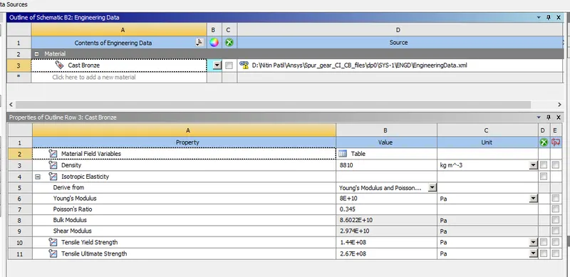
Geometry :
- Import cad file in Geometry and open it in space claim.
- To check weather cad model is fine or not,if any error will found then fix it.
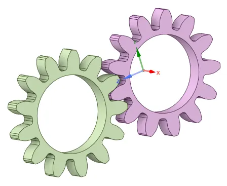
Model :
- Check the geometry details and assign material from there as required.
- Define contacts by selecting teeth contacting surface.
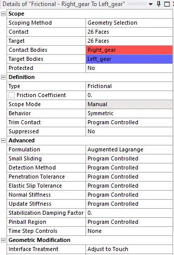
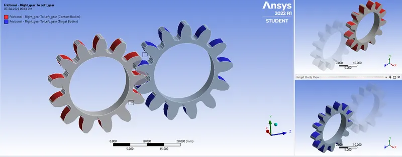
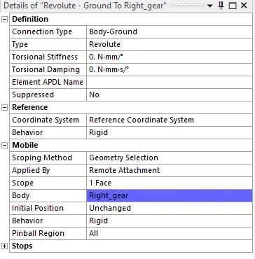
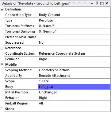
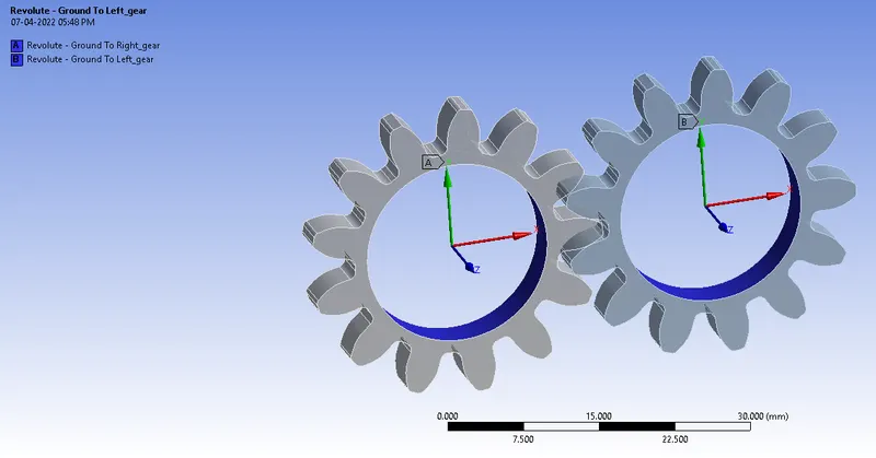
- Joints :
For Right Gear
For Left Gear
Meshing :
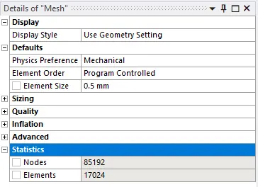
- Give element size of 0.5 mm.
- Generate mesh.
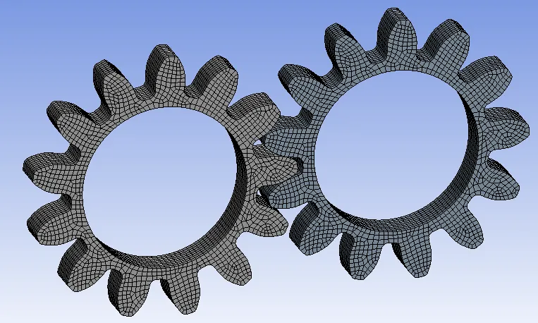
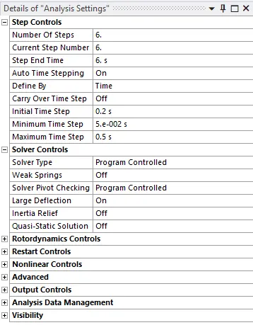
Analysis Setting :
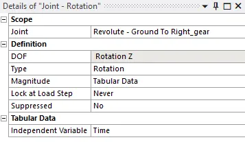
Joint Load :
For Right Gear
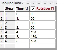
For Left Gear
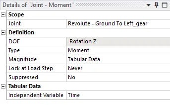
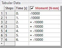
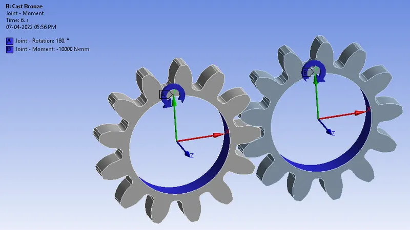
Solution :
- We will create output results for total deformation, equivalent stress, equivalent strain and stress intensity.
- Click on Solve.
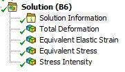
Results :
A) Objective 1 :
Case 1 : Using Cast Iron as a material.
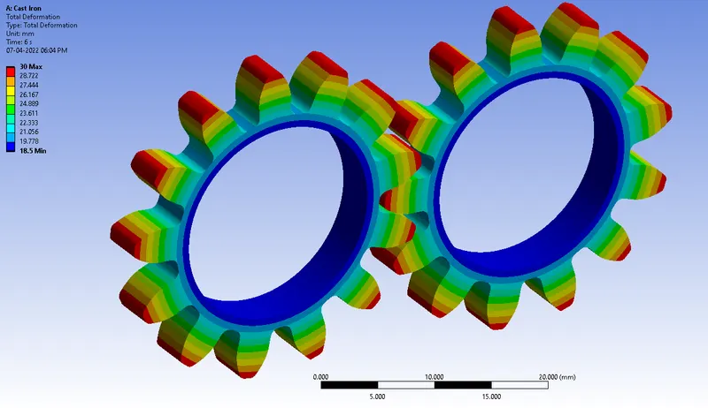
Total Deformation :
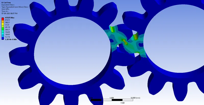
Equivalent Stress :
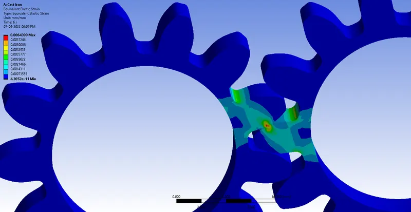
Equivalent Strain :
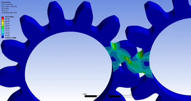
Stress Intensity :
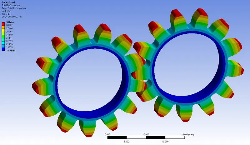
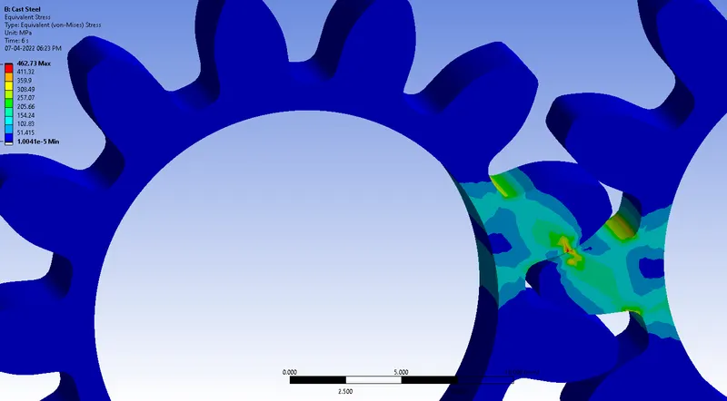
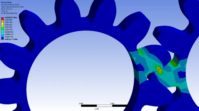
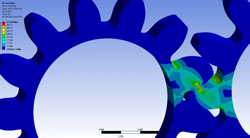
Case 2 : Using Cast Steel as a material.
Total Deformation :
Equivalent Stress :
Equivalent Strain :
Stress Intensity :
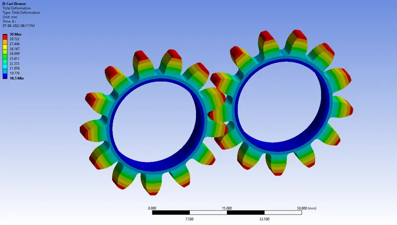
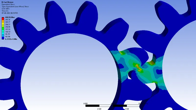
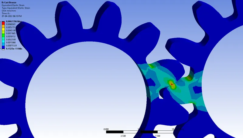
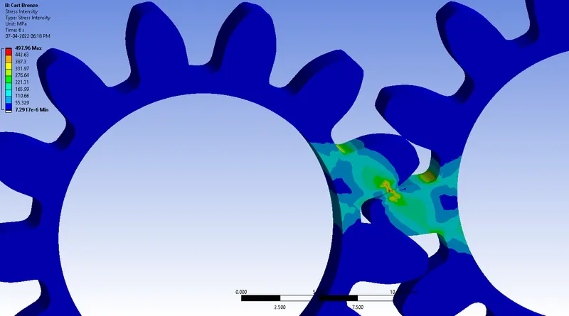
Case 3 : Using Cast Bronze as a material.
Total Deformation :
Equivalent Stress :
Equivalent Strain :
Stress Intensity :
Objective 2 : Comparing the results of the three cases.
| Sr.No. | Results | Cast Iron | Cast Steel | Cast Bronze |
| 1 | Total deformation Maximum (mm) | 30 | 30 | 30 |
| 2 | Total deformation Minimum (mm) | 18.5 | 18.5 | 18.5 |
| 3 | Equivalent Stress Maximum (Mpa) | 470.85 | 462.73 | 444.56 |
| 4 | Equivalent Stress Minimum (Mpa) | 3.3014 E-6 | 1.0041 E-5 | 6.3312 E-6 |
| 5 | Stress Intensity Maximum (Mpa) | 533.12 | 521.68 | 497.96 |
| 6 | Stress Intensity Minimum (Mpa) | 3.7951 E-6 | 1.0932 E-5 | 7.2917 E-6 |
Conclusion :
-
For all three materials, the maximum stress was observed in the root of the teeth. Similarly, the stress intensity measured was also found to be maximum in the same region.
-
The deformation is however found to be similar for all the cases.
-
Equivalent Stress : Cast Iron > Cast Steel > Cast Bronze.
-
Stress Intensity : Cast Iron > Cast Steel > Cast Bronze.
- From the results, it is observed that the equivalent stress and the stress intensity is maximum for cast iron and minimum for the cast bronze.
- The smaller values of stress intensity assist the part in achieving a longer life.
- Hence, from the analysis, it can be considered that cast bronze is the a typical material for the spur gears due to the lower values of equivalent stress and stress intensity experienced by the material for the same boundary conditions.
The stress intensity factor (K) is used in the field of fracture mechanics. It predicts stress intensity near the tip of a crack caused by a remote load or residual stresses.
The magnitude of K depends on:
- Sample geometry
- Size and location of the crack
- Magnitude of load
- Distribution of load
The following equation describes stress intensity:
Where ß describes the relationship between gross geometrical features to the stress intensity factors. ß can be a function of crack length as well as other geometrical features. K represents nominal stress that is remote from the crack.