Week 1 Spur Gear Challenge
Objective
To perform a static analysis on spur gear using three different materials (Cast iron(ductile), Cast steel, Cast bronze) and to find out Equivalent stress, Total deformation, and Stress intensity also the location of failure.
Procedure
- A new Ansys file was opened and a static structural module was dragged onto the project schematic window.
- The given model of the spur gear was imported to the geometry by right clicking>geometry>insert.

- Here the simulation for the gear was modeled with three different materials, taken one at a time for a comparison of the result. So we take cast iron as our first material.
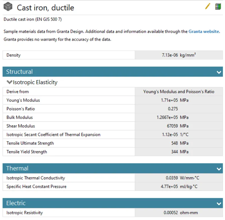
- To set up the case study model option was selected from the module.
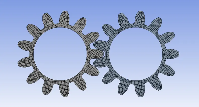
- The model consists of two similar gears and it can be renamed as left and right gears using F2.
- Meshing was done using an element size of 0.5mm and the smoothing was kept as low.
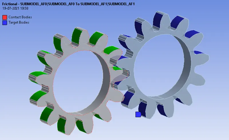
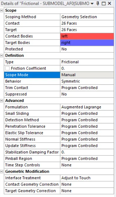
- For the connection, a default contact set was there that was already set due to the automatic contact detection. So we need to reselect all the faces that will be in contact throughout the simulation. There is no need to select all the surfaces from a part since it will take a long time to compute, so the area where it's in contact was selected. Contact type from definition was given as frictional, behavior is symmetric, changed interface treatment to Adjust to touch, also a formulation of Augmented Lagrange was used. This type of formulation was used because when teeth come in contact with each other they will tend to move off or slip from their position. So to correct that issue this type of formulation can be used.
- A joint is defined for gears to rotate it about an axis. A revolute type of joint was defined for both parts. This can be done using right-click contact>insert>joint. Connection type was defined as body-ground (Specifying the frame of reference), type as revolute. Now select the inner surface to define the scope as shown below.
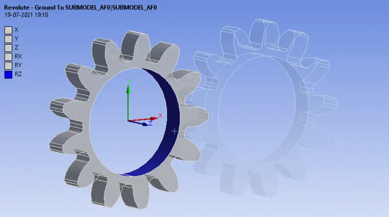
- Create another joint definition for other parts as well to select the scope.
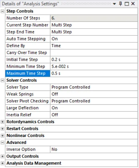
- Now analysis can be done to look at the contact forces, stresses, strains developed for one revolution of the gear. Here the spur gear at an angle of 180 degrees by an increment of 30 degrees in each step (Total six steps). So in analysis settings under static structural 'Number of steps' was changed to six and select all the steps using the control key. Now select all the six steps and from the solver control switch "on" the large deflection also the auto time stepping turned "on" and change the Define settings to by time. Other settings are made as shown below.
- After that joint loads were applied and can be done by right-clicking static structural>insert>joint load. For the left gear rotation was defined and for the left gear moment was defined. While giving the values the direction of the rotation should be noted. When values are defined both gears had the same direction of rotation so the value of the moment was given a negative sign.
- Below shows the table for specifying the joint for the left gear.
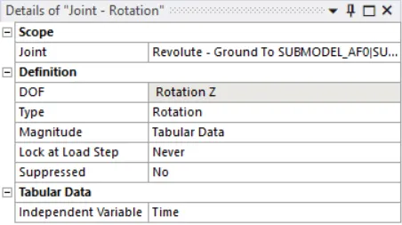
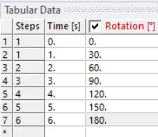
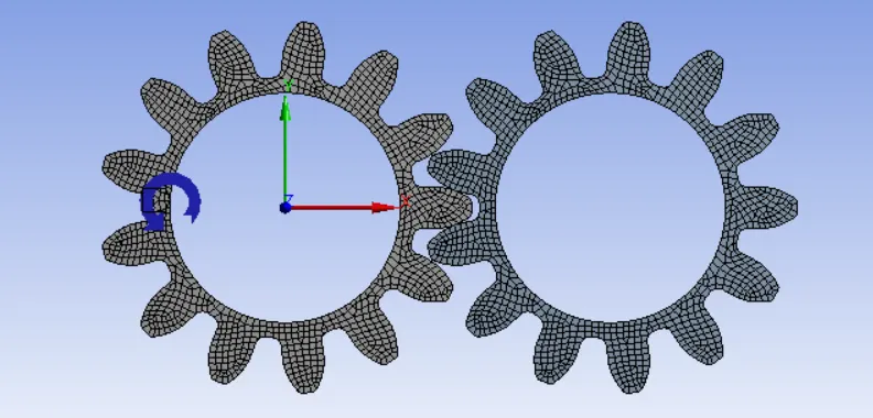
- Below shows the table for specifying the joint for the left gear.
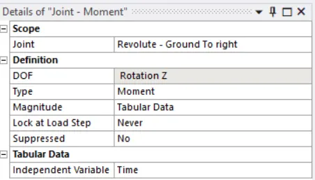
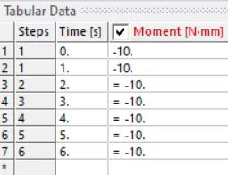
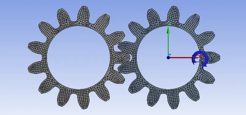
- Now the simulation was solved by requesting output such as stress intensity, equivalent strain, and total deformation.
- The same procedure was followed to get the results for the model using cast steel and cast bronze material.
Results
Static analysis was performed for the given gear model using cast iron(ductile), cast steel, and bronze to find out the equivalent stress, total deformation, and stress intensity and compared the results.
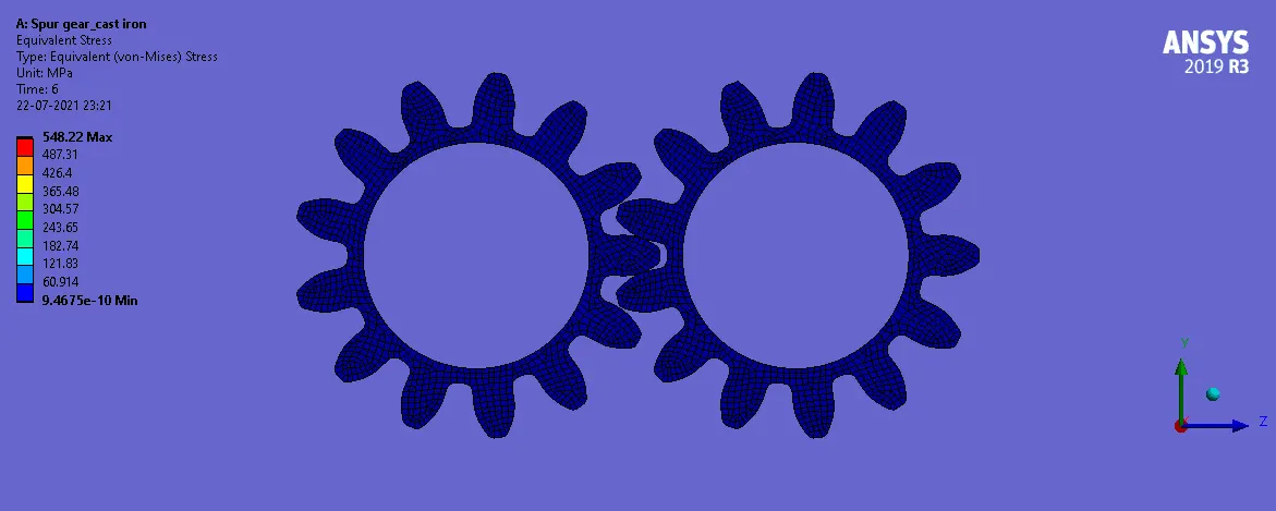
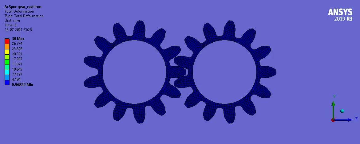
Below results show the behavior when modeled with cast iron(ductile).
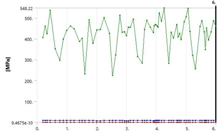
Equivalent stress
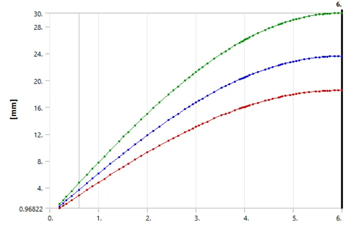
Total deformation
Stress intensity
- The stress intensity is used in the field of fracture mechanics. It predicts stress intensity near the tip of a crack caused by a remote load or residual stresses.
-
The magnitude of stress intensity factor (K) depends on:
- Sample geometry
- Size and location of the crack
- Magnitude of load
- Distribution of load
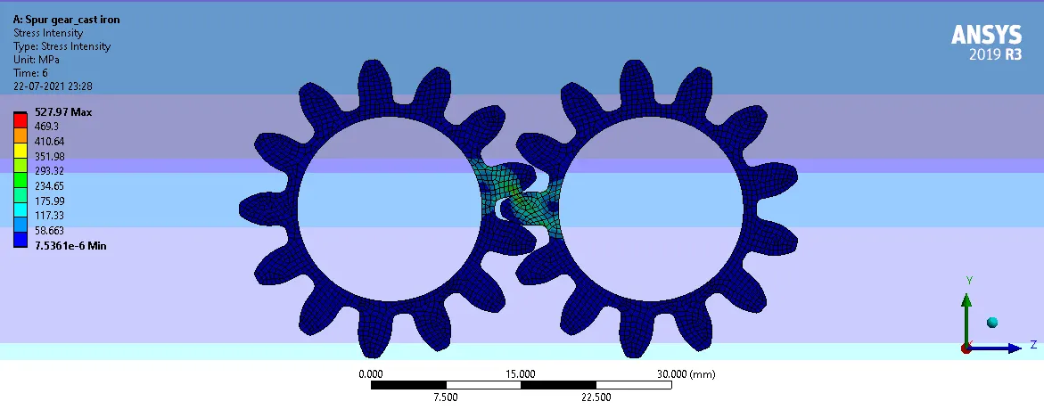
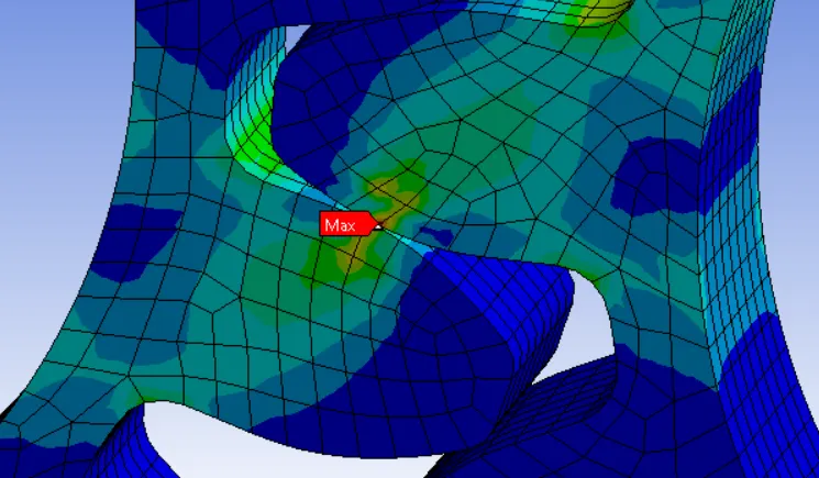
- The location of possible failure was found to at the mating region as shown below.
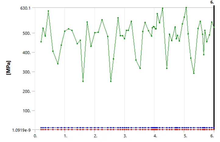
- Green curve = Maximum value
- Blue Curve = Average value
- Red curve = Minimum value
Finally, the results for the material modeled with cast bronze and cast steel were obtained and then tabulated for comparison.
Comparison of results
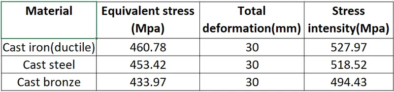
- The total deformation was found out to be the same for every material used.
- The maximum equivalent stress and stress intensity were found to be the maximum for cast iron(ductile) and the minimum for cast bronze.
Conclusion
- A spur gear is the most basic type of gear available. It consists of nothing more than a cylinder or disk with radially projecting teeth aligned parallel to the rotational axis. The simplicity of spur gears means that they are commonly used in a number of machines, from cars to household appliances. Because they are used often, spur gears must be built of materials, like plastics and metals, that are easily fabricated and molded, but also strong and durable.
- From the result, we found out that the cast iron has the maximum equivalent stress and stress intensity. Because of that, the chance of failure will be high for the material when compared to the other two materials. Cast iron gears are very cheap, have excellent machinability, generate less noise, and have a very good wear Strength. They are not preferred for long-term use due to fact that they have very low Strength.
- Even though the stress values from the results are low for cast bronze and from an analysis point of view this is a great option for modeling the gear, but bronze is not much popular in Spur gear design but is indeed extensively used in worm gear work because it can withstand high sliding velocity. It can be easily worked, has a low coefficient of friction, and also can be used where corrosion is a major problem.
- For the cast steel, the values for the stress intensity comes between the cast iron and bronze. Cast steel has manufacturing flexibility and the variability of cast steel parts is strongest. Cast steel parts can be used for a variety of different conditions, the comprehensive mechanical performance is better than that of any other casting alloy. Cast steel has the advantage of having a high strength-to-weight ratio, high resistance to wear, the ability to enhance physical properties through heat treatment, and competitive pricing.
So, From the analysis results we got, cast bronze can be chosen as the preferred material since the stress intensity was found to be less thus making it less prone to failure and the least preferred material as per the analysis result is the cast iron(ductile). here the stress intensity is very high and the crack propagation takes place at a faster rate which leads to the failure of the material.
..............................................................................................................................................................................
File: https://drive.google.com/drive/folders/1BtZICW7iHABVJFfwMHFRmYlgF_KyCuv7?usp=sharing