Week 1:- Introduction to BiW and Fixtures Challenge
QUESTION 1: What is BIW and define its parts?
Answer1 –
Body In White (BIW) refers to the welded sheet metal components which form the vehicle structure to which the other components will be joined i.e. engine, chassis, interior and exterior trim.
Body In White (BIW) refers to the stage in automotive design or automotive manufacturing in which the car body sheet metal (including doors, hoods and deck lids) has been assembled or designed but before the components (chassis, motor) and trim (windshields, seats, upholstery, electronics, etc.) have been added.
BIW is the stage in automotive design or automobile manufacturing in which the car body sheet metal components are been assembled by welding or by the other joining process.
To achieve an efficient car design it is necessary to BIW design with optimized mass. BIW connected all the components in the vehicle like powertrains, driveline, etc.
BIW design also needs to be lightweight structure so that there can be a possibility of reduced fuel consumption and increased performance.
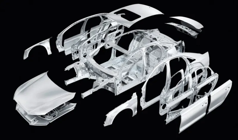
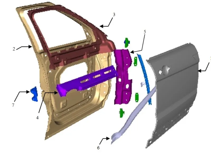
Exploded view of BIW components:
Major Influencing Factors Of BIW Design:
1. Number of parts
2. Materials
3. Internal structural reinforcements
There are two types of Body structures in use,
1. Monocoque Body
2. Frame Mounted Body
1. Monocoque Body Structure:
In this type of body structure, Chassis is inbuilt in the BIW itself and there is no separate chassis. Wheels are directly mounted to the BIW with the help of a suspension system.
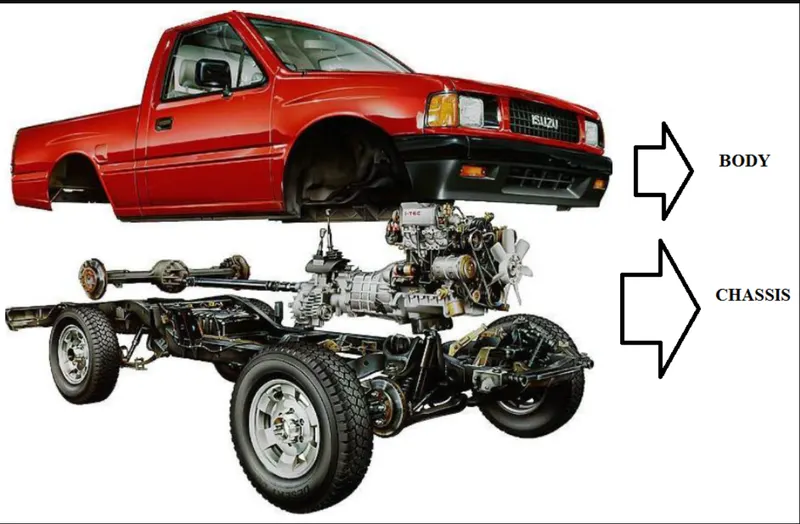
2. Frame Mounted Body Structure:
In this type of body structure, the Body is mounted on the separate chasssis or frame and wheels are mounted on the chassis, not to the body.
BIW PARTS:
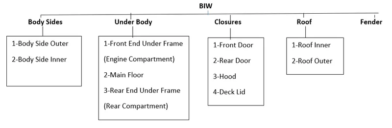
BIW structures can be divided into the follwing sub-structures:
1. Underbody Structure
2. Front End structure
3. Body Side Structure
4. Closures
5. Roof
6. Reinforcement
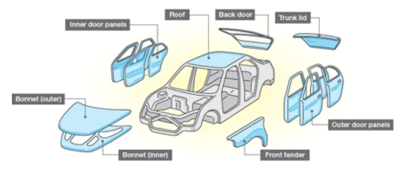
Basic Parts in BIW are discussed as follows:
1. Body sides:
The side ward parts of the BIW structure falls into this category.
1.Body side Outer: This refers to the sideward outer parts of the body/frame.
2. Body side inner: This refers to the sideward inner parts of the body/frame.
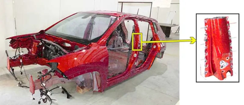
2.Under body:
The bottom/downward parts of the BIW structure falls into this category.
1. Front end under frame: This refers to the frame under the front end i.e. under the engine bonnet.
2. Main floor: This refers to the frame under the middle i.e. under the seats.
3. Rear end under frame: This refers to the frame under the rear end i.e. under the boot cabin.
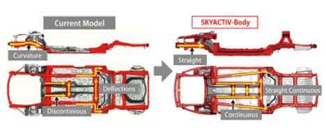
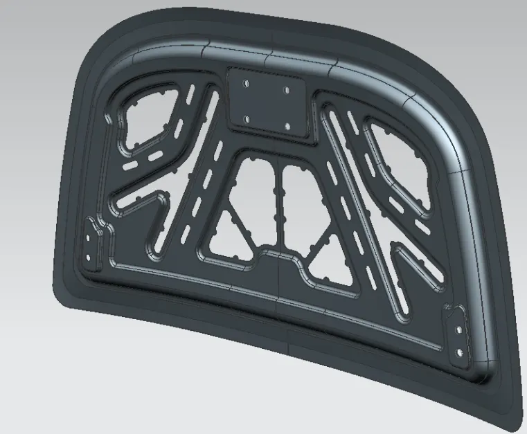
3.Closures:
The closing parts of the BIW structures such as doors/lids parts fall into this category.
1. Front door: This refers to the parts of front door panels of the automobile.
2. Rear door: This refers to the parts of rear door panels of the automobile.
3. Hood: This refers to the closure door the hood of the automobile.
4. Deck lid: This refers to the closure lid of the deck of the automobile.
4.Roof:
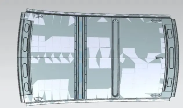
The top covering parts of the BIW structure falls into this category.
1. Roof inner: This refers to the inner side of the roof surface.
2. Roof outer: This refers to the outer side of the roof surface.
5.Fender:
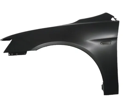
A fender is the curved portion of the car’s body that sits over and houses the wheels.
Its primary purpose is to prevent sand, mud, rocks, liquids, and other road spray from being thrown into the air by the rotating tire.
QUESTION 2.What do you understand by BIW nomenclature?
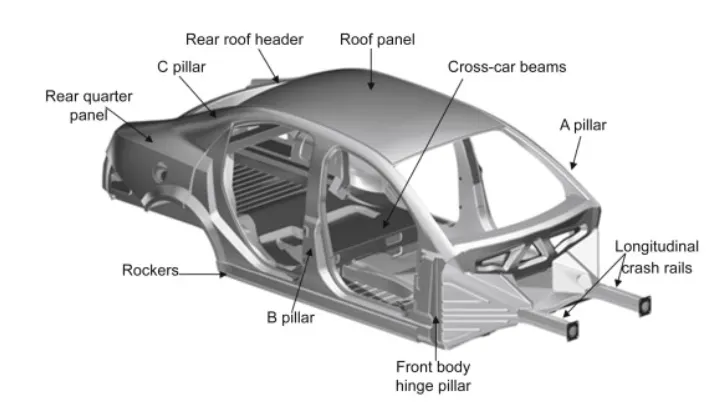
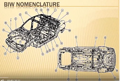
A nomenclature in BIW is basically naming every part of the body. These names can be said as subparts of the already categorized parts above. The nomenclature differs a little bit from region to region but the overall idea is to name individual automotive sheet metal components. Below images show the nomenclature of BIW:
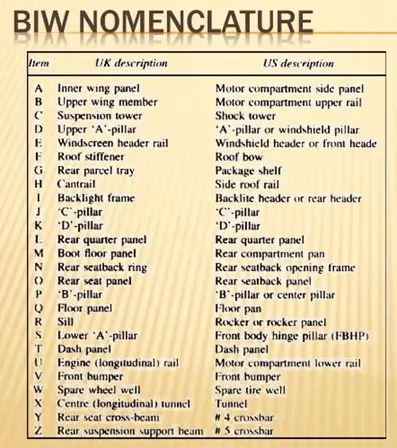
- The terms are standard but they differ in some countries.
- As automotive industries spread worldwide, the terms and standards will be different for similar components.
- For example, One component of BIW is known as inner wing panel in the UK description another side the same component of BIW is known as the Motor compartment side panel in the US description.
QUESTION 3: What is Fixture and its types?
Answer:
A Fixture is a device which holds the workpiece to be processed (welded), By using 3-2-1 Principle.
In general, a welding fixture (tool) consists of no of units together to hold the car panel, and is mounted on a base unit.
Welding fixtures are normally designed to hold and support the various components (work pieces) to be welded. It is necessary to support them in a proper location which is capable of preventing distortions in work pieces during welding.
For this the locating elements need to be placed carefully, clamping has to be light but firm, placement of clamping elements has to be clear of the welding area and the fixture has to be quite stable and rigid to withstand the welding stresses.
Types Of Fixtures:
- Production Fixtures – Mass Production Purpose.
- Pre-production Operation Fixtures (PPO) – For initial batch production to study the feasibility.
- Checking Fixtures – For car panel geometric inspection purpose.
1. Production Fixtures:
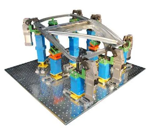
This fixture is used for mass production It requires high consistency through its operation to maintain the geometry of the parts so the material used is well tested for hardness & aesthetics. The quality for maintaining the dimensions & tolerances are also checked.
The production fixtures need to easy for maintenance purposes. The fixture needs some maintenance after completing no. of operations. The time requires for assembly & disassembly should be as low as possible which saves lots of time.
2. Pre-Production Operation Fixtures (PPO):
These fixtures are designed as a prototype fixture to check the feasibility of initial batch production & to check which things need to be improved before starting.
These fixtures can be taken as the base fixtures which sets the benchmark & criteria which help us to rectify the errors that we could get from preproduction operation fixtures. In this many manual operations are involved, many engineers & quality-related persons are required.
3. Checking Fixtures:
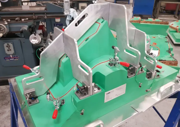
As the name suggests these fixtures are used for checking No operations like welding gluing or hemming are carried out in these fixtures.
The gauges are used in these fixtures to get the dimensions & the tolerances part having & the data is compared with the designed dimensions to check whether the part is ok or not. The geometry of the welded parts is also checked in these fixtures to ensure the parts maintain the required dimensions & geometry.
QUESTION 4. What is the basic priciple of fixture design ?
- The fixture is designed based on how the workpiece is fixed on the fixture. All the Degrees of Freedom of the workpiece are to be constraint.
- The 3-2-1 principle is used.
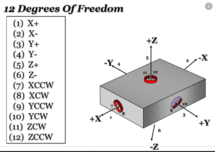
- The workpiece has twelve Degree of Freedom. six transitional DOF and 6 rotational DOF.
- Transistional: X, -X, Y, -Y, Z, -Z.
- Rotational: Clockwise around X axis (CROT-X); Anticlockwise around X axis (ACROT-X); Clockwise around Y axis (CROT-Y); Anticlockwise around Y axis (ACROT-Y); Clockwise around Z axis (CROT-Z); Anticlockwise around Z axis (ACROT-Z).
- The rotational DOF have to be constraint.
- Using 3-2-1 priciple.
- First the workpiece is constraint by 3 pins on below surface. This lock the Y DOF,Clockwise around X axis (CROT-X); Anticlockwise around X axis (ACROT-X) the Clockwise around Z axis (CROT-Z); Anticlockwise around Z axis (ACROT-Z).
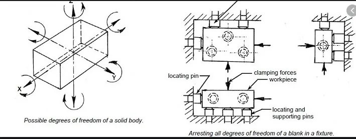
- Then another side perpendicular to the below surface is constraint by 2 pins. This locks -Z and +ZDOF and Clockwise around Y axis (CROT-Y); Anticlockwise around Y axis (ACROT-Y).
- Then any one side perpendicular to both the below and the other 2 side of the workpiece is constaraint by 1 pin. This locks X DOF.
- The part is now fully constraint and cannot move
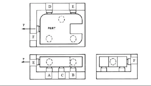
- The 3 points are used as 3 points to define a plane. Four points cannot be used due to irregularity of the surface in real world.
QUESTION 5: Elaborate types of BIW Stations?
Answer:
Tool: A tool is a fixture which consists of no of units together to hold the car part in general.
Types of Tools:
1. Geo Tool: A geo tool is fixture in which the geometry of the panels which are welded together is defined accurately. The pin tolerance for the geo pin will be of closure tolerance i.e., 0.15 in general.
For example:
Consider the panel hole size 20mm, the pin diameter should be 19.85mm.
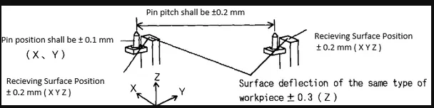
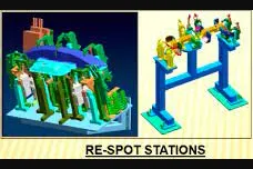
2. Re-spot Tool: A re-spot tool is a fixture in which the remaining weld spot which are not achieved in geo tool are welded for the pre-welded panel from the geo tool.
The pin tolerance for the re-spot pin will be of tolerance of -0.28 in general.
For example:
Consider panel hole size is 20mm, the pin diameter should be 19.72mm.
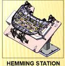
3. Marriage or Hemming Tool: A marriage or a hemming tool is a fixture in which the inner panel assembly and outer panel assembly are joined together.
These are done by welding or by hemming in case of closure panels.
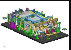
4. Checking Stations: A checking station tool is a fixture which is used to check the automotive parts or assemblies, ensuring all the coordinates, relative dimensions and positions as per the tolerances. A checking station can be a gauge type, fixed type and automated checking fixtures.
A checking gauge is a tool where work piece is hold and various measuring gauges are introduced to ensure the dimensions and repeatability.
A fixes type checking fixture is used where the workpiece is fixed with clamps and pins and a CMM machine is used which measure the coordinates of different points of the panel or assembly, compares it with the nominal values and gives a report.
GRIPPERS:
A gripper is a device or a fixture which holds the car panel, and is fixed to the manipulating end of a robot or an end effector. Also known as EOAT – End Of Arm Tooling.
Types of Grippers:
1. Material Handling Gripper (MH): Material Handling Gripper are designed for handling the car panel from one tool (station) to other tool (station).
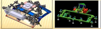
2. Process Gripper: Process Gripper are designed for handling the car panel from one tool (station) to other tool (station), and in addition to that it under goes process like pedestal welding, pedestal riveting, Gluing, sealing, etc.
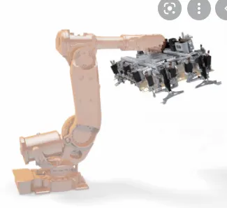
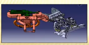
3. Combo Gripper: Combo grippers are designed for handling the car panel from one tool (station) to other tool (station), also with the combination of weld gun at another side of the gripper for welding.
For example: Gripper + Weld Gun.
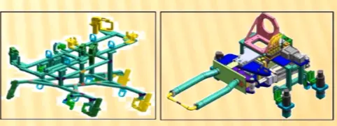
4. Dual Gripper: Dual gripper are designed for handling the car panel from one tool (station) to other tool (station), with two-sided gripper.
For example: Gripper + Gripper.
STANDS AND TYPES OF STANDS
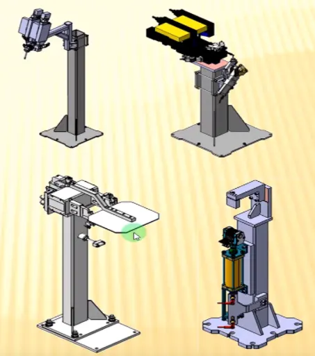
1. Gluing and Sealer Stand: Gluing gun or sealer gun is fixed to a welded or a standard stand which is grouted to the floor permanently.
2. Docking Stand: When robots are selected for multitasking like material handling and welding, which cannot carry both due to some limitations (pay load capacity of the robot or space constraint) the robot will drop and pick the gripper or gun after completing the respective operation with the help of Docking stands.
3. Date Stamp Stand: The panel will get the date embossed on to it, with the date stamping device mounted on this date stamp stand.
4. Pedestal Gun Stand: Weld gun is mounted to a fixed stand which is grouted to the floor permanently, Where the process gripper carries the car panel to weld the spot with this fixed weld gun.
Miscellaneous:
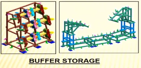
1. Buffer Storage: After some operation, we can put the no. of assemblies in this stand which is buffer stock & it can be transported to another station in easy They are also used to store the inventory while the machine is undergoing some maintenance.
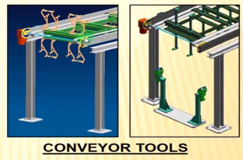
2. Conveyor Tools: The conveyor id the rotating paht that transports the parts to the next station which kept over it.
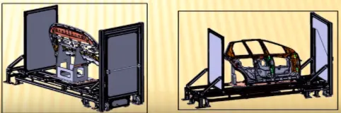
3. Take Out Trolley: Take out trolley is used to take the car panel out of the robotic working cell between the cycle for inspection purpose.
4. Curing: After gluing it needs some time to cool sown, so we put the assembly on some belts and ot will take the panel to another station and meanwhile gluing will cool down.
QUESTION 6. What are the basic terminologies used in the BIW fixture?
Basic terminologies used in the BIW fixture
- The following terminologies are used in BIW
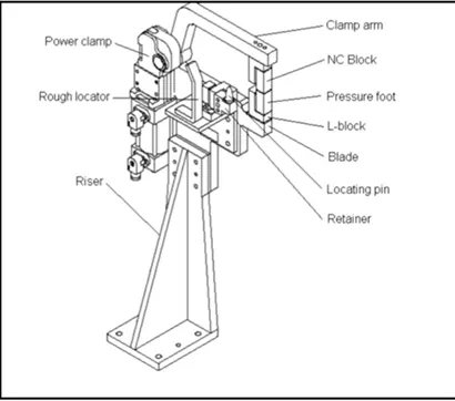
- A) NC/Mylars/Fingers
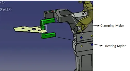
- Mylars are the component that holds the panel while These are placed from topside & from the bottom side also. The top side Mylars called Clamping Mylars & the bottom side Mylars called Resting Mylars. Every clamping Mylars have resting Mylars. It doesn't allow deformation of the part due to welding stresses.
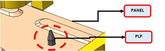
- B) Principle locating point (PLP)
- These are the points that are used for the accurate location of the part to maintain the geometry of the part. There is lots of holes on the panel which are not accurate due to stamping operation. The PLP are defined in the drawing. The positional dimensions or relative dimensions are very precise in stamping & in fixtures also.
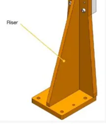
- C) Risers
- Risers are of different types like L-typer rises, Square tube riser Riser is the manufacturing part which gives height to the assemblies.
- D) Blade
- Blades are plates mounted on the Other parts like cylinder, arms, etc are mounted on the blade.
- E) Shims
- Shims are the small part that comes with the thickness of 0.1mm, 0.2mm, 0.5mm, etc. These will compensate for the stackup tolerance which reflects at the panel holding part called We give tolerance to all the parts of the fixture. Due to this tolerance, the Mylars will either lift up or goes down from their defined position.
- If the Mylars go down from the defined height it will make an impression or dent on the panel.
- If the Mylars lift up then there will be a distorsion due to welding stress. To adjust the Mylars At its defined position we use shims so the panel won't be deformed & also don't get any impression on it.
- F) Rough locators
- The operator can place the part in the wrong orientation The rough locator will work as a guide while placing the part in the fixture & the part will be loaded in the desired orientation. It is a part of foolproofing.
- G) Hardware
- Hardware is like the Hex head bolts, Allen Bolts, Hex nuts, Spring washers, Self-locking nuts
- H) CMM
- CMM stands for coordinate measuring machine. It is a device that measures the geometry of physical objects by sensing discrete points on the surface of the object with a probe. It generates a report by comparing the data with the CAD file data.
- I) Unit
- The fixture is the assembly of different types of units to form a part. There are different units like pin unit, base unit, clamping unit, etc.
- J) Number plates
- The number plate is the aluminum embossed plate placed on each unit for easily recognizing the part unit.
- K) Nameplate
- The data like manufacturing company name, fixture type, Fixture weight is embossed on the plate & joined to the fixture.
- L) Clamp Arm
- The clamp arm is the part of the clamp unit which moves an Over clamp arm the Mylars are mounted.
- M) Pivot
- It is an axis about which the clamp arm will rotate
- N) Class A Surface/Skin surface
- The outer panels of the car like a hood, door, backdoor, fender, roof are visible to the customer.
- The outer panels should be aesthetically very good. No scratches or dent is acceptable over it.
- While designing the fixture to the skin surface the clamping material should be soft, so that it could not able to left any impression or dent over the skin. generally, nylon or PU material is used for clamping purposes.
O)Reed switches & sensors
- These are the electric components used in automated The reed switch is an electrical switch operated by an applied magnetic field. The detects the panel is loaded or not is done by sensors.