Week 1:- Introduction to BiW and Fixtures Challenge
BIW INTRODUCTION
1. What is BIW & define its parts?
EXPANSION: Body in White (BIW)
DEFINITION:
• Body in white or BIW refers to the stage in automobile manufacturing in which
The car body sheet metal has been assembled but before the components
(like., engine, chassis, exterior and interior trim) have been added.
• A Body in White is an assembly of a frame and panels made up of homogenous materials
(like., instance, steel, or aluminium sheets or composites)
• It is the stage in automobile manufacturing in which a car body’s frame has
been joined together that is before painting and before the motor chassis
sub-assemblies or trim have been joined into the structure.
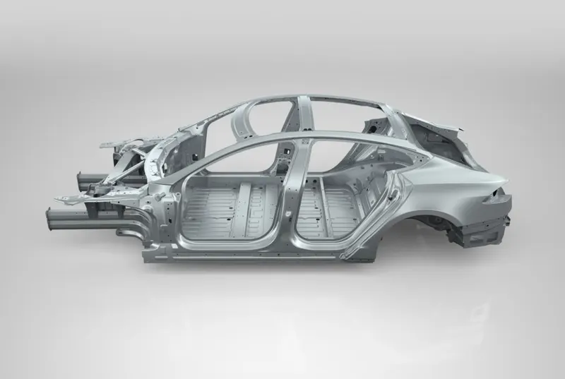
This image is welded BIW structure before priming and painting :
Parts
1. Under body structure
2. Front end structure
3. Body side structure
4. Closure
5. Roof
Definition
• Under body structure
This image shows the under body structure of the BIW
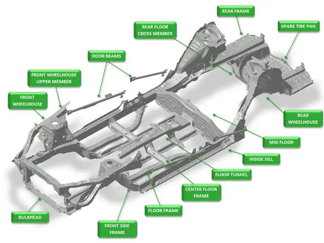
1. Dash panel – it provides a partition between engine and cabin
inside car
2. FRT – it provides a base for car seats and also provides a partition
between cabin and propeller shaft/ground
3. Riser – riser connects front floor to rear floor by providing a level
difference
4. Rear floor – rear floor is the floor on the rear of the car and
provides a partition from ground and also provide base for rear
seat mounting
5. Rear wheel house
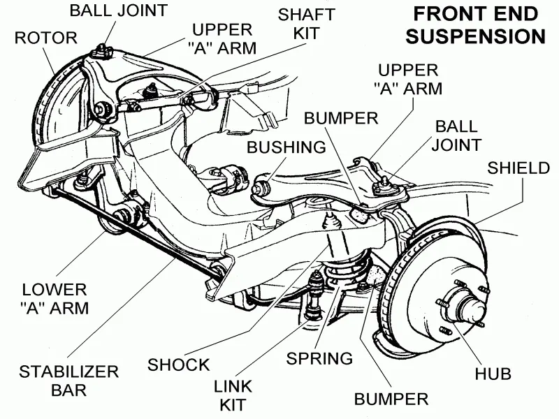
• Front end structure
This picture shows the front end structure of the BIW
1. Plenum panels – plenum is a chamber located between the
throttle body and the runners of the intake manifold used to
distribute the intake charge evenly and enhance engine breath
This image shows the plenum panels in front end structure
2. FRT – it is an encasement around the FRT Wheel
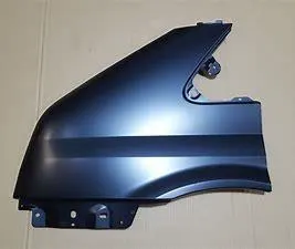
3. Wing panel – wing panel are the outer most side panel in the front
This image shows the wing panel in the front end structure
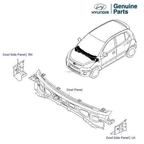
4. Cowl – cowl is the partition of the body bounded by the front
fenders, the base of the windshield and the rear edge of the hood
These below image is shows that is the cowl panel
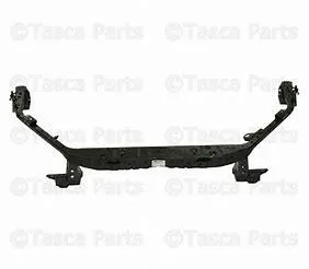
5. Upper tie bar – upper tie bar is the upper panel in front
connecting the two sides of front structure
6. Lower tie bar – lower tie bar is the lower panel in front connecting
the tow sides of front structure
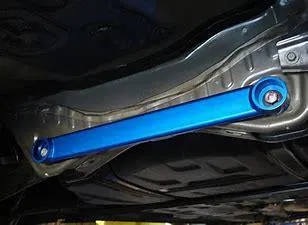
• Body side structure
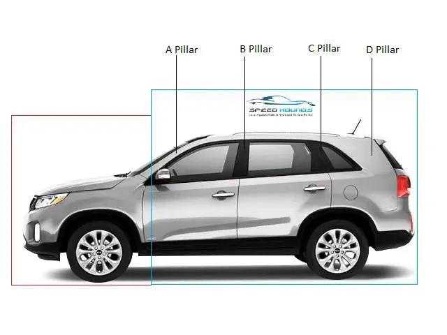
1. ‘A’ pillar – it is the front most support to the roof
2. ‘B’ pillar – it is the second support to the roof and situated
on the locking side of the front door
3. ‘c/d’ – ‘C’ pillar is the rear most support to the roof in case
of a two rows seats car , or third support to the roof .
‘D’ pillar is the forth support to the roof and usually and the
rear side of quarter
4. Ring panel – ring panel is a structure panel connecting the
rear partition of the body to front and constitutes a big part
in side structure
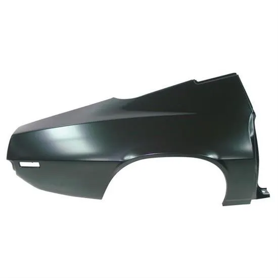
5. Quarter panel – quarter panel is rear most panel of a body side structure
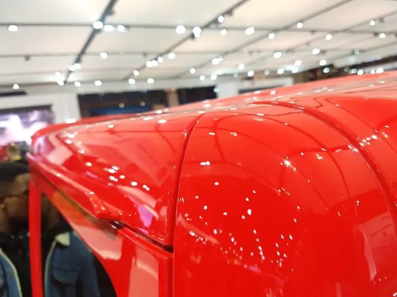
6. Drip rails/ gutters – drip rails / gutters is an exposed channel
applied to the roof over the side windows to direct water
away from the windows and to cover structural welding
• Closures
1. All doors
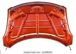
2. Hood / bonnet
• Roof structure
1. Roof
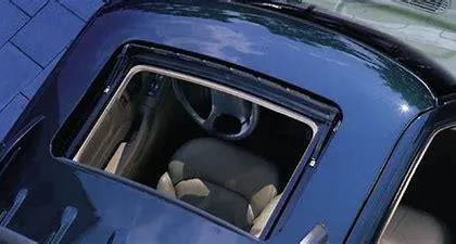
2. Header
3. Rows
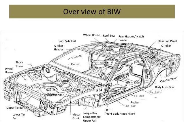
2.What do you understand by BIW Nomenclature?
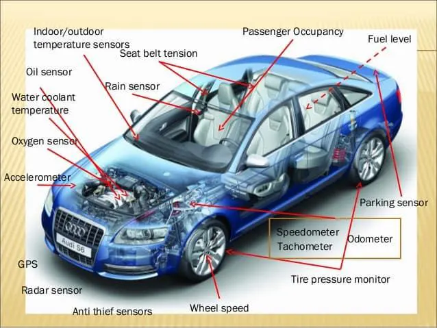
• Nomenclature is basically choosing names for thing BIW have no of parts in it .
All parts have different names
| Item | UK Description | US Description |
| A | Inner wing panel | Motor comportment side panel |
| B | Upper wing panel | Motor compartment upper rail |
| C | Suspension tower | Shock tower |
| D | Upper ‘A’ panel | ‘A’ Pillar |
| E | Windscreen header rain | Front head |
| F | Roof stiffener | Roof bow |
| G | Rear parcel tray | Package shelf |
| H | Can trail | Side roof rail |
| I | Backlight frame | Rear head |
| J | ‘c’ pillar | ‘C’ pillar |
| K | ‘d’ pillar | ‘D’ pillar |
| L | Rear quarter panel | Rear quarter panel |
| M | Boot floor panel | Rear compartment pan |
| N | Rear seatback panel | Rear seat back opening frame |
| O | Rear seat panel | Rear seat back panel |
| P | ‘B’ pillar | ‘B’ panel |
| Q | Floor panel | Floor panel |
| R | Sill | Rocker panel |
| S | Lower ‘a’ pillar | Front body hinge pillar (FBHP) |
| T | Dash panel | Dash panel |
| U | Engine rail | Motor compartment lower rail |
| V | Front bumper | Front bumper |
| W | Spare wheel well | Spare tire well |
| X | Centre tunnel | Tunnel |
| Y | Rear seat cross beam | # 4 cross bar |
| Z | Rear suspension support beam | # 5 cross bar |
3.what is fixtures & Its types?
❖ Definition
• Fixture is device which holds the work piece to processed by using 3-2-1
principle
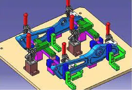
• In a general fixtures consists of number of units together to hold car panel
together
• Welding fixtures are normally designed to hold and support the various
components to be welded
• It is necessary to support them in proper location which is capable of
preventing distortions in work pieces during welding.
• The fixture has to be quite stable and rigid to with stand the welding stress.
❖ Purpose of BIW Fixture
• It should prevent distortions in work piece during welding operation
• The clamping need to be light but firm means the clamping force should be
able to maintain the part at its required position without damaging the part
• Placement of clamping need to be clear of welding area
❖ BIW fixture types
1) Production fixture
2) Preproduction operation fixture (PPO)
3) Checking fixture
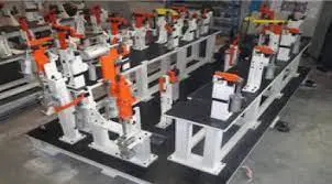
• Production fixture – this fixtures are used for mass production purpose .
it requires high consistency through its operation to maintain the geometry of
the parts so the material used are well tested for the hardness & aesthetics.
And then the time requires for assembly and disassembly should be as low as
possible which saves lots of times.
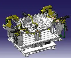
• PPO (preproduction operation fixtures) – these fixtures are design as a
prototype fixture to check the feasibility of initial batch production & to check
which things need to be improved before starting the production.
These fixtures can be taken as the base fixtures which sets the benchmark & criteria
which help us to rectify the errors that we could get from preproduction
operation fixtures. We have to maintain the cost of car as low as possible.
its requires lots of time and cost also.
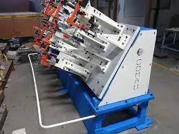
• Checking fixtures – as named suggest these fixtures are used for the checking purpose.
no operations like welding, gluing, or hemming are carried out in this fixtures.
the geometry of the welded parts is also checked in this
fixtures to ensure the parts maintain the required dimensions & geometry.
4.principle of Fixture design ?
• For any free body there are have total twelve degrees of freedom as below,
➢ 6 translation degrees of freedom: +x, -x, +y, -y, +z, -z
➢ 6 rotational degrees of freedom
Clockwise around x axis (CROT-X )
Clockwise around x axis (ACROT-X )
Clockwise around Y axis (CROT-Y )
Clockwise around Y axis (ACROT-Y )
Clockwise around Z axis (CROT-Z )
Clockwise around Z axis (ACROT-Z )
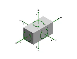
• You must fix all the 12 degrees of freedom in order of locate the workpiece in fixture .
so we arrest the 12 degrees of freedom of the workpiece and
we achieve the zero degree of freedom for the work piece .
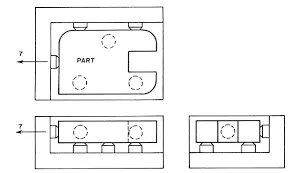
• Locating principle
➢ 3-2-1 principle : holding fixtures used in assembly operation of
follow a 3-2-1 locating scheme to position of parts
➢ Under this scheme, Three locators position a part in a primary
plane or direction on (high / low )
➢ Two locators then position the part in secondary plane or direction (in / out )
➢ Leaving one locator for the tertiary direction (front / back )
➢ This approach fixes the part in 3 dimensional space and statics the
degrees of freedom constraint
5.TYPES OF BIW STATIONS?
• In BIW assembly lines in where different types of panel are joined in together
in each specified zones
• Each panel categories will have individual zones
• Zones are classified by under body zone , door zone , hood zone .,. etc
• Stations
➢ Tool stations
➢ Gripper stations
➢ Stand stations
➢ Miscellaneous stations
• TOOL STATIONS
1) Geo stations -
geo tool is a fixture in which geometry of the panels which are welded
together are defined accurately ,
the pin tolerance for geo pin will be of closure tolerance (i-e) -0.15 in general
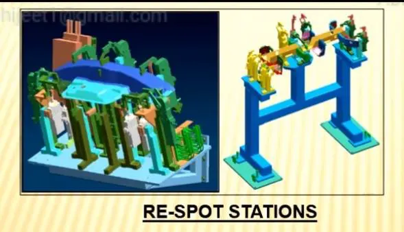
2) Re-spot stations
Re-spot tool or stations is fixture in which the remaining weld spot
which are not achieved in geo tool are welded for the pre welded for the pre
welded panel from the geo tool .
The pin tolerance for re-spot stations will be of tolerance with – 0.28 in general
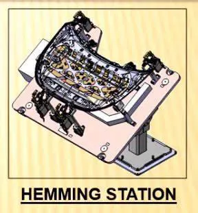
3) Hemming stations
A marriage or a hemming tools is fixture in which the inner panel
assembly and outer panel assembly are joined together .
These are done by welding or hemming in case of closures panels
4) Framer stations
Framer fixture is next stations after marriage stations . in framer fixture
roof is attached to output of the marriage fixture and it from like frame hence
it is called as framer tool
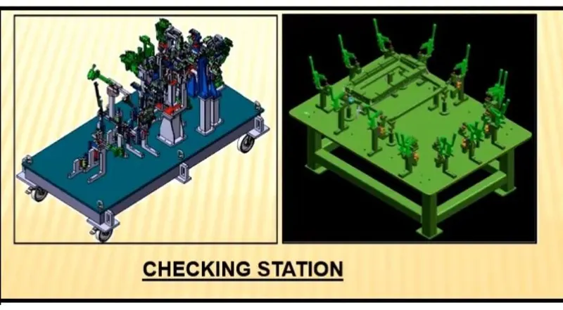
5) Checking stations
A checking stations tool is fixture which is used to check the automotive
parts assemblies ,ensuring all the co-ordinate , relative dimension and
position as per the tolerance
A fixed type checking fixture is used where work piece is fixed with
clamps & pins & CMM machine is used which measures the co-ordinates of different points
of the panel or assembly \
• Gripper stations
1) Material handling grippers – material handling gripper is designed for
handling the car panel from one station to other
2) Process grippers – process grippers are designed for handling the car
panel one stations to another stations & in addition to that it under
goes process like welding , pedestal , riveting , gluing , sealing .,.etc
3) Combo gripper – combo gripper is designed for handling the car panel
from one stations to another stations also with combination of weld
gun at another side of gripper for welding .
4) Dual gripper – dual gripper is designed for handling car panel from one
tool to other , with two sided gripper . it can hold two panel
simultaneously one RH & one LH side .
• Stand stations
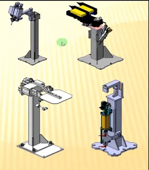
1) Pedestal stations – weld gun is mounted to the floor permanently.
The gripper can carry the panel under the stand to do some operations
2) Gluing & sealer stand – gluing or sealer gun is attached to standard
stand which is grouted to floor permanently fixed is required ,
so stand should not move due to vibration or other factors .
3) Docking stand – when robots are selected of multitasking like
material handling & welding , which cannot carry both due to some limitations .
it is also called as parking stand for gripper .
4) Date stamp stand – every manufactured product have some data to
stamped or to be embossed on it like serial no , batch no , date etc .
The required data is stamped or embossed by using the
stamping device mounted on stand .
• Miscellaneous stations
1) Curing – after gluing it needs some time to cool down ,
so we put assembly on some belts & it will take the panel to another station &
meanwhile gluing will cool down .
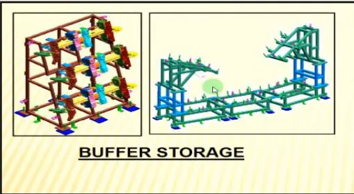
2) Buffer stand – after some operations we can put no .
of assemblies in this stand which is buffer stock & it can be transported to
another station in easy way
3) Take out trolley – it is used to take out some panels for inspection to
rectify the process is going in right or not between the cycles .
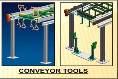
4) Conveyor – conveyor is material handling .they are used to transfer
panel from one station to another station . it can be of two types gravity & powered
6.what are the basic terminologies used in the BIW fixture?
➢ The basic terminologies used in BIW are
1) Nc/mylars/fingers
2) Principle locating point
3) Risers
4) Blades
5) Shims
6) Rough locators
7) Hard wares
8) CMM
9) Units
10) Co-ordinate points
11) Name plate
12) Clamp arm
13) Number plates
14) Pivot
15) Read switches and sensors
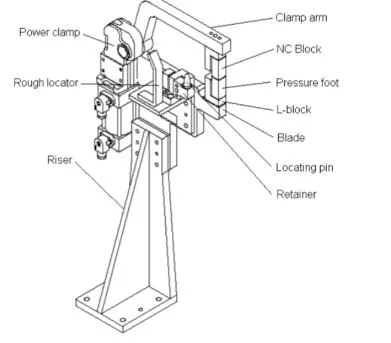
1) MYLARS – These parts are used to hold the panel .they are globally called as MYLARS .
top side mylar is called as clamping mylar & bottom side mylar is called as resting mylar.
2) PLP-principle locating point which are used for the accurate location of part to maintain
he geometry of assembly ,means principle locating points are those where we use pin
for locating panel
3) Risers – risers can be of L-type , welded or square tube or frame type .
these are basically manufactured parts are use to give height to assembly .
4) Blades – blades are plates attached to riser . other part likes cylinder,
arm etc are mounted on the blade .
5) Shims – in fixture we providing tolerance to each parts mostly manufactured .
those tolerance tend to stack up & reflect together .
in order to avoid that we use shims so we can easily adjust after assembly
so whatever stack up there we will rectify it through shims . shims come in
thickness of 0.1, 0.2,0.5 etc .
6) Rough locators – rough locators are those used majorly for manual fixture .
there is chance that operator can place part in wrong orientation mistakenly.
The rough locator will work as a guide while placing the part in fixture &
part will be loaded in desired orientation.
7) Hardware – hardware are like the hex head bolts , Allen bolt , hex nuts ,
spring washers , self locking nuts , etc .,.
8) CMM – CMM stands for co ordinate measuring machine .
its is a device that measure the geometry of physical objects by sensing discrete
point on the surface of object with probe
9) Units – this fixture is assembly of different types of units to form a fixture.
There are different unit like pin unit , base unit , clamping unit , etc
10) Number plates – number plate is the aluminium embossed plate placed on
each unit to recognize the unit .
11) Co-ordinate plates – when we discuss about fixture on every fixture
we have tooling hole which is called master hole through all fixture checked
on CMM mastering the particular hole .
12) Name plate – the plate on which basic information described like company name ,
fixture name , fixture weight , panel name , are embossed and joined to fixture
13) Clamp arm – clamp arm is part of clamp unit which moves about axis ,
over clamp are mylars are mounted
14) Pivot – it is axis about which clamp arm will rotates
15) Read switches & sensors – these are the electric components used in automated .
fixtures is fully automated or semiautomatic that run through PLC , control panel etc
sensor are used to defect part present or not clamp is close or open where as reed
switches confirm position of piston i.e. it is at top or down .