Week 3:- BiW Fixture Design Methodologies Challenges
DESIGN METHODOLOGY
1. What is Design Methodology?
Refer to the development of a system or method for a unique situation
Design methodology is nothing but the steps followed during the concept designing stages of fixture design
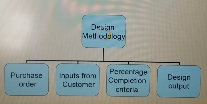
❖ Purchase order
❖ Input form customer
❖ Percentage completion criteria
❖ Design output
- Purchase order The purchase order is the document received from the customer which gives the details of the product, time plan.
- Input form customer
The customer given the detailed of the fixture corresponding to the standard followed by the Compony
- Percentage completion criteria
It gives details about the project completion and the estimated time period to completion the project
- Design output
The 3D 2D CAD files along with the GD&T have to be submitted to the customer.
The documents such as BOM (Bill of Material) have to be submitted
2. What are the input required from the customer to start designing a fixture?
Input required form the customer start designing fixture is following type
❖ Functional Requirements
❖ Preferred Standard components
❖ Car Product
❖ Layout
❖ Ergo Data
❖ Weld Study
❖ Standard Detailing Templets
➢ Functional Requirements
In this the information about what kind of function the fixture is going to have such as
welding, reverting, gluing, etc., will be given.
➢ Preferred Standard components
The detailed of the standard parts that the compony is using are given
which saves a lot of time as the design is not required and the compony no need to purchase from outside.
➢ Car Product
The 3D and 2D files of the car design, what kind of car product the fixture has to be modeled.
The study of GD&T and the PLP (Principle locating points of the car).
➢ Layout
The layout of the assembly line. To understand the flow of the process,
to construction the part in that flow
➢ Ergo Data
This is the standard data that every compony will have. If the data is given the fixture are
designed accordingly. This gives the data about how comfortable the operator operates the
machine
➢ Weld Study
This is an important study in fixture design. This gives the details of where the weld gun
Is located, what kind of weld gun is used. The entire fixture design depends on I.
➢ Standard Detailing Templets
Every compony is having a different standard templets and need to get
the data in the same format
3. What is the input we get from ‘’Car Products’’?
Car Products include
1. GD & T
2. Part List
3. Cad Files of Car Part
4. Clamp Plan
5. Product assembly Process Sheet
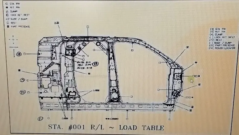
➢ GD&T
The gives the geometric dimensioning and tolerance information which includes the datums,
feature control frames. Locating pins, Rest, Clamp, dumps and slides information of each
station. The sequence of opening of clamps, dumps and slide stroke information
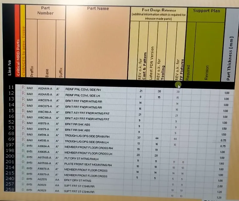
➢ Part list
The gives information on what kind of assembly the part is going to be. For example,
the assembly of the hood inner panel and outer panel, latch and striker assembly, so different
assembly will have different fixture units so the part files are made according to the fixture unit.
➢ CAD files of car part
3D and 2D CAD files of car product
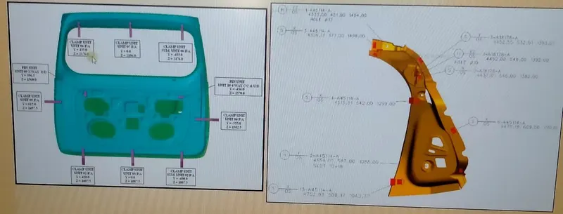
➢ Clamp Plan
It is a very important input from the car product. The position of clamping units of
the particular pin unit placement details are given The important point is never to change
the position of the clamp given in this data. The design can be changed according to the clamp
➢ Product assembly process sheet
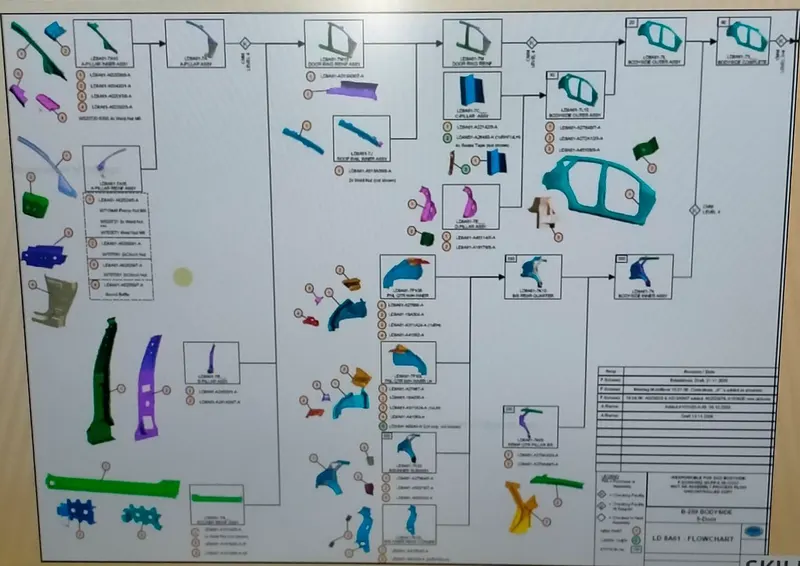
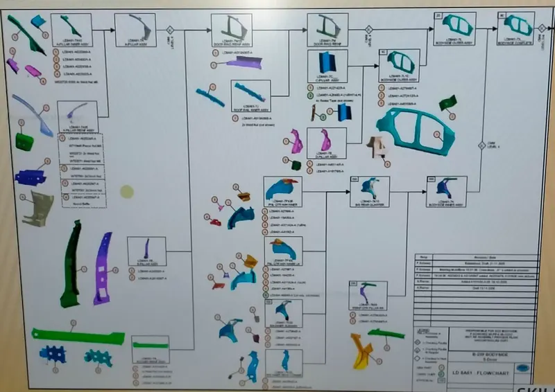
It gives the details of how the assembly of parts takes place.
If there are any constraints need to contact the customer so they will change according to
the requirements. This provides theinformation of the assembly line, cycle time.
4. What is the clamp plan?
Clamp plan provides the information of location of pins, Rest units, clamp unit, Dumps etc.
It is the important input from customer. The clamp plan/position should not be changed without
the knowledge of customers
5. What is the purpose of a layout?
The main purpose of the layout is to know the space constraints and to design the fixture accordingly
The above fig. gives outlook of the layout in the industry where the fixture and robot are placeed
according toTheir sections. The circles indicate the swept area of the, which is the area
it can be covered. The name geo_250_TO1, geo indicate the purpose of the tool here
it is geo tool, 250 is the name of the section and TO1 is the Tool number one
❖ Layout provide information
❖ Flow of parts
❖ Station pitch
❖ Robot Station
❖ Accessories like Tool changer and tip dresser
❖ Sub assembly links
❖ Platform height
❖ Loading/Unloading Sequence/heigh
- Flow of part It informs about the movement of parts from one station to another station.
- Station pitch It gives the distance between two station and the constraint of space between the two station in
the industry. - Robot station
The robot location and the swept area information is provided.
- Accessories like Tool changer and tip dresser
If the robot wants to change the tool, it has to go toa particular tool station and come back to
its location. Tip dressers are for weld gun which sharpens the tips.
- Sub assembly lines
It gives information about how the assemblies are linked to the main assembly line..
- Platform height
- Loading/Unloading sequence/heights
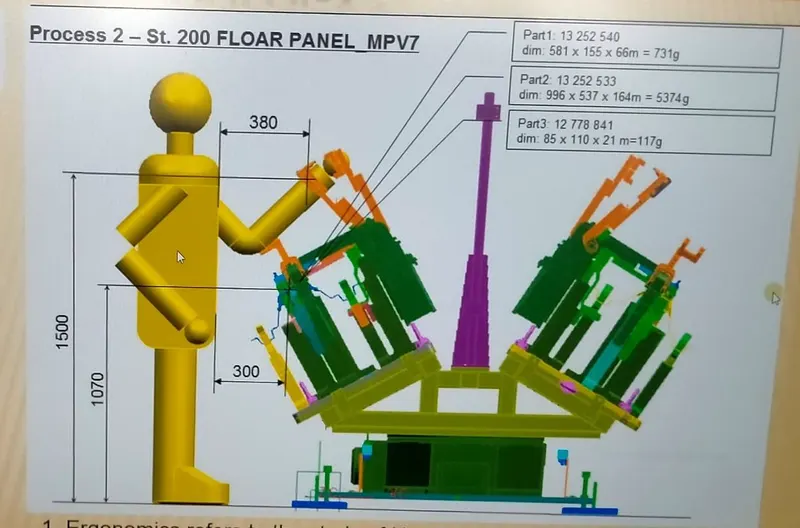
6. What is ergo data?
Ergo data refers to human behavior and movement. It provides information about loading height,
working Safety zone of the operator. The ergo data are standard and depend on the compony
7. What do you understand by weld study?
Welding is a fabrication process that joins materials, usually metals or thermoplastics,
by using high heat to Melt the parts together and allowing them to cool,
causing fusion welding is distinct from lower Temperature metal-joining technique such as
brazing and soldering, which do not melt the base metal.
Weld Study include
- Weld gun details.
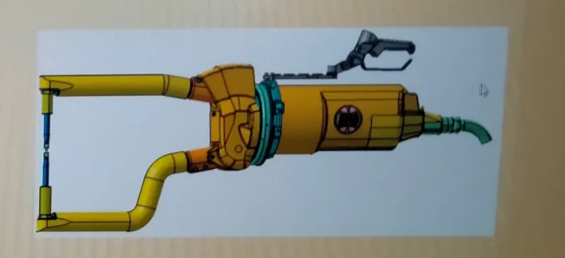
- Weld matrix & weld points
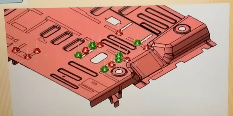
- Geo weld points
- Re-spot weld points
8. What are the criteria for percentage completion in the designing stage? Explain it in detail.
Percentage completion is followed in designing stages and dispatch stages in the welding fixture.
It provides information about the workflow of the project. In which stage the project is currently. By
This data, the project completion time can be provided to the customer. There are four different stage
There are four different stages.
1. 0-25% - Input and concept design
2. 25-40%- Concept approval and simulation check
3. 40-85%-Design freezing and detailing
4. 85-100- Check and final dispatch
❖ 0-25% - Input and concept design
The fixture study, designing of the CAD model occurs at this stage.
If the design of the modell completed
then the project will be 25% completed. If the design doesn’t complete
in the specified time limit but only
a certain portion of the design is incomplete then the project completion will be less than 25%.
❖ 25-40%- Concept approval and simulation check
Once the CAD modelling is completed, the design is sent to the simulation team where they will check
the design whether it is a according to the details gives by the customer or not.
The assembly simulation areconducted.
If the design passes all the simulations then the project will be 40% complete
❖ 40-85%-Design freezing and detailing
After the simulation, the design will be freezer and all the details will be checked
❖ 85-100- Check and final dispatch
Once the detailing is completed the design will be sent to QC (quality check) department.
Once the QC department agrees then the fixture goes to the manufacturing unit
The percentage criteria are updated at each stage to the customer and the exact deadline will be provided
9. Brief about ‘’output’’ in design
The output is 3D model and the 2D drawing of the tool
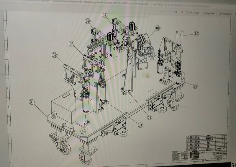
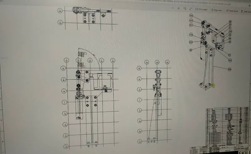
Unitized tools (multiple tools on the common base) require two types
- Key Sheet- An index of unit and their placement on the tool base
- Layout Sheet- A detailed drawing of individual units that include all of their component
- Non – utilized tool
Tools that can stand alone and completely detailed in a layout sheet.
The output should compline the following points.
• Approved standard components are to be used wherever possible
• Design must be as simple and economical as possible
• Design must comply with all current safety and ergonomic requirements.
• Adequate error-proofing provision must be incorporated into
each design by providing proximity switches, rough locators etc.
• The weight of the moving parts must be kept to a minimum while maintaining maximum strength.
• Frames and structure are to be simple and sturdy
• Design clearance and accessibility for routine maintenance and service
• Motion control must be considered on any moving equipment.
• Designer is responsible to validate clamps and all weld guns.
10 What do you understand by structuring a design tree? How does it reduce errors during the design process?
❖ Structuring a design tree implies to a process where all the assemblies & parts are named in a
specific standard.
Different customers have different set of standards to structure a design tree.
❖ It is an important process which helps us to identify a specific part or assembly,
as to which project, tool or unit, it belongs to.
❖ This helps us to avoid the errors during design study, manufacturing, assembly inspection etc,
❖ If the parts or assemblies are not named properly or the design tree is not structured properly,
it will create confusion to understand the design & may create major possibilities of making
an error.
❖ Naming of a fixture or a unit or a part, gives the information as to which project or zone or
assembly do they belong.
❖ It can help us to identify the quantity of items of same type or different types that are being
used in an assembly
11. What are units? Mention 5 types of units.
The location and orientation of other critical units of the fixture including clamps, locators etc.
they are decided based on the weld spot distribution. The weld spots for panel-side bracket
assembly are located with respect to the body line of the car
- Fixed pin unit- it is fixed to the base and it cannot be moved
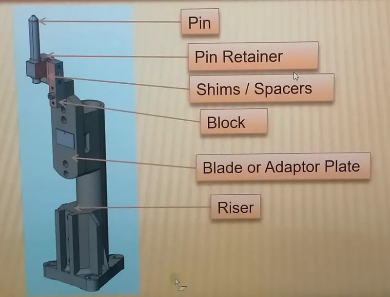
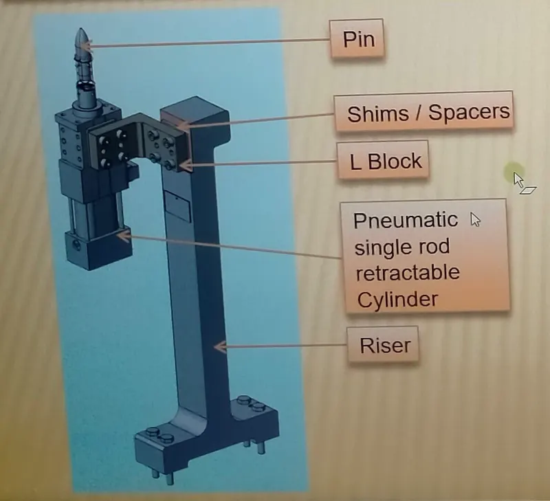
- Retract pin unit- it is a loading unit that can be moved.
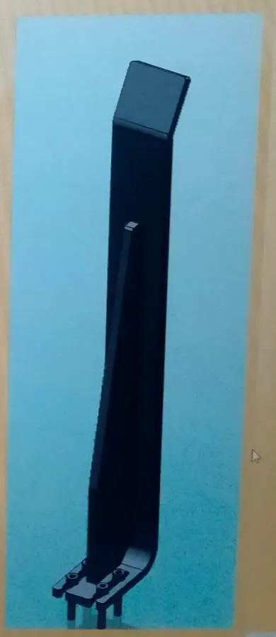
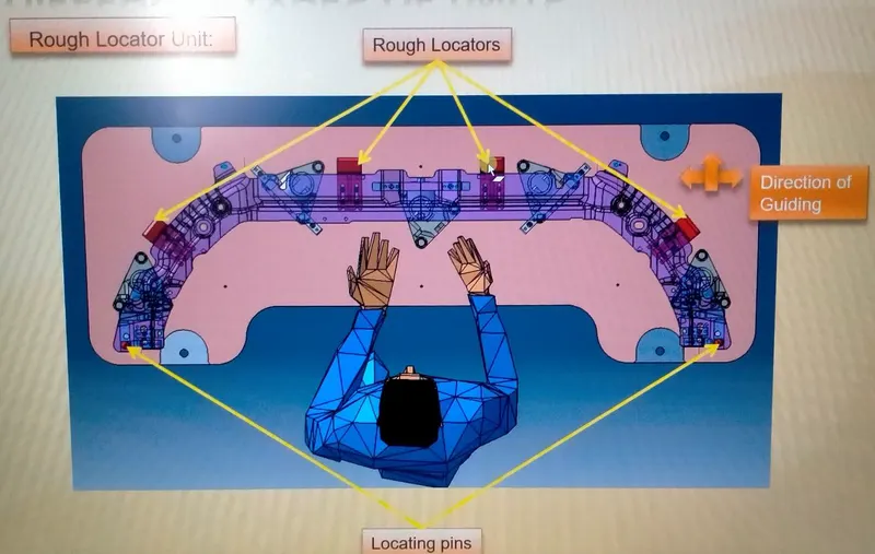
- Rough locator unit- it roughly guides the operator for locating the part.
A Rough locator is apart designed to guide the operator, to locate the car panel on to the pins accordingly.
A rough locator can be of standard part or make part.
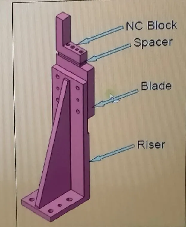
- Rest unit- the panel is set on this unit.
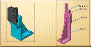
A rest unit is a unit designed to rest/ support the car panel using NC blocks / Mylar / Rest.
And below are the different part of a rest unit in general.
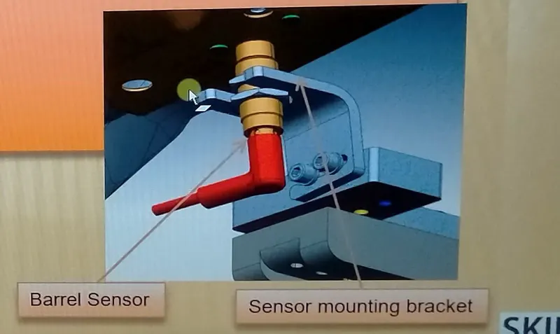
❖ Sensor unit
A sensor unit is a unit designed to sense the car panel by using Electrical sensors.
This signal from the sensors will be fed to the PLC and so the next process will be executed by this signal
❖ Base unit
A base unit is the unit designed to mount all the other units (Clamp unit, Pin unit rest unit etc.)
Of the tool, also other parts necessary for a tool like pneumatic Valve box,
trunking cable path will also be mounted on to a base unit.
And below are the some part of a base unit in general
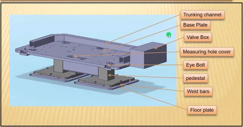
12. Describe fixed pin units & their purpose
Fixture pin unit hold the car part family and prevent the part from distortion while carrying out
the Spot welding
A single clamping unit consists of the following parts.
❖ Finger
The finger is a movable part that is used to hold the car parts from the top against the back-up and
they are usually mounted on the clamp arm.
❖ L-Block
L- shaped blocks (single or in combination) used to mount the finger to clamp arm,
besides allowing adjustment for locator pin in two directions.
❖ Shim and shaper
They allow the finger to be moved to the correct XYZ locating and/or allow the customer to make
adjustment to improve the quality of their product.
❖ Blade
Part on to which the aforesaid elements are attached to.
❖ Blade spacer
It allow the finger to be moved to the correct location in one direction.
❖ Riser
L-Shaped tall block with regularly patterned holes to attach the above-mentioned parts in a modular
way blade space
13. What are the different part of a fixed unit?
Fixture pin unit hold the car part family and prevent the part from distortion while carrying out
the Spot welding
A single clamping unit consists of the following parts.
❖ Finger
The finger is a movable part that is used to hold the car parts from the top against the back-up and
they are usually mounted on the clamp arm.
❖ L-Block
L- shaped blocks (single or in combination) used to mount the finger to clamp arm, besides allowing
adjustment for locator pin in two directions.
❖ Shim and shaper
They allow the finger to be moved to the correct XYZ locating and/or allow the customer to make
adjustment to improve the quality of their product.
❖ Blade
Part on to which the aforesaid elements are attached to.
❖ Blade spacer
It allow the finger to be moved to the correct location in one direction.
❖ Riser
L-Shaped tall block with regularly patterned holes to attach the above-mentioned
parts in a modular way blade space
14. What is the purpose of making a Rest unit & describe its parts?
These unit are used to rest the panel. Take an overview of the working height if you’re having manual welding.
For robotic welding also it’s important to see the working height consideration of the robot gun,
turntable height if manual loading is done.
Put the proper gun at the spot location for all the spots near the rest unit.
If process engineer has gun shape stick to X, C or Y type of gun.
Do the proper gun study and place the gun as per the geo or re-spot described and operator approach .
Once basic gun is placed considering the throat depth and throat gap start
15. What are the basic fundamental to design a sensor unit?
• Every single loose panel which are being welded in a tool should be sensed.
• Each panel should be sensed by 1 to 2 sensors depend on the size of panel,
preferred to be in diagonal opposite ends of panel.
• Every sensor should be mounted in a 3 direction adjustable way in general
- Some major sensor manufactures are IFM, Pepperl- fuchs, SICK, OMRON etc.
Type of sensors used in general
• Proximity sensors
• LASER sensors
• Photo electric sensors
16. What is a Rough. locator unit & what are the fundamental to consider while designing it?
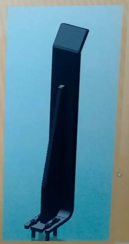
A Rough locator is a part designed to guide the operator, to locate the car panel on to the pins accordingly.
A rough locator can be of standard part or make part.
Fundamentals of Rough locator design.
• Rough locators should be placed at the edges of the car panel, which it has to guide
• Rough locators has to be placed in the same angle of the car part edge with a minimum distance of 2-5mm from the edge of the car part.
• Rough locator should guide the panel in pin arresting direction. (in general)
• Rough locator should start guiding the panel before 10 to 15 mm to the start of the pin engagement.
• Rough locator should be designed with entry angle for car part entry.
• Rough locators should be designed with two slots to mount for easy adjustments. (in general)
• The slots should be in the direction of car part guiding.
17. What is a base unit and described it’s parts?
A base unit is the unit designed to mount all the other units (Clamp unit, Pin unit, rest unit etc.)
Of the tool, also other parts necessary for a tool like pneumatic valve box, trunking cable path will also be mounted on to a base unit.
And below are the some parts of abase unit in general
❖ Trunking channel
A trucking channel is a hollow rectangular or semi-circular structure mounted on the base unit to
give strength an support to the units are to be mounted
❖ Base plate
It is the surface of the base unit where all the units are fixed. The base plate acts as a supportive
structure that is firmly attached to the fixture.
❖ Valve box
The pneumatic operations valve are placed in the box and it is attached to the base unit.
❖ Measuring hole cover
These are reference holes, from which the X, Y and Z coordinate data are taken.
❖ Eye bolts
Used to lift and place the fixture in different locations.
❖ Pedestal
These are the supporting structure to the base plate from the ground. It can be adjusted to the height
of the designer
❖ Weld bar
Welding rods are used in shielded metal arc welding (SMAW), also known as stick weldin
❖ Floor panel
It is used to mount the fixture at a particular location.
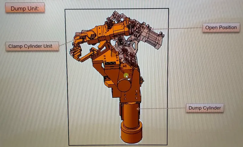
18. What is a dump unit and what are its function?
It is a complex unit to design due to space constraints there is less space available & have to adjust
all the parts in available space. It consists of a dump cylinder to perform the operation of clamping & unclamping car panel.
If there are any geometrical constraints unit can be used.
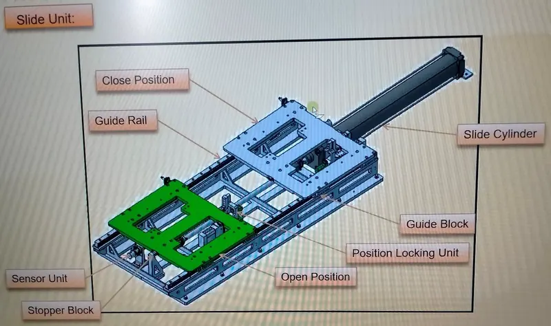
19. What is a slide unit? Mention where slide units are commonly used.Slide units are positioning units are used to position the car part,
❖ fixture, weld gun robots into position for further operations.
❖ Slide units may be classified into two types based on the type of guide-way used as hardened guide way anLM guide way.
❖ Slide units may further be classified into there types based on the prime mover used as manual slides. Hydraulic / pneumatic slide and CNC slides
❖ It may be further classified as Horizontal, Vertical and angular slide units depending on the application.
❖ LM guide ways are preferred over hardened guide ways due to the least co-efficient of friction
❖ Slide unit essentially consists of LM guide, linear cylinder, front and rear stoppers, front and shock absorbers,
two proximity switches / reed switches for sensing the two end positions, bellows or protection cover for rails.