Week 1 : Exploring the GUI of GT-POWER
AIM:
1. Explore the GUI of GT SUITE and list down modules available with brief description. (15 marks)
2. Locate following settings:
- Time control flag (5 Marks)
- Time step and solution control (5 Marks)
- Integrator/Solver type (5 Marks)
3. Explore intercooler tutorial and note down all settings of:
- Run setup (5 Marks)
- Advanced setup (5 Marks)
- Plot setup (5 Marks)
- Output setup (5 Marks)
4. Problem: (50 Marks)
Given
- Diameter of cooler inlet and outlet pipe= 50 mm
- Length of the CAC= 1000 mm
- Inlet mass flow rate = 1200 kg/ h at 100 degC
- Outlet pressure 2 bar at 30 deg C
- Calculate the Average heat transfer at Charge air cooler (CAC)
- Calculate pressure drop across CAC
This the aim of this particular challenge and the detail report along with detail results are folloing below;
MODULES AVAILABLE IN GU-SUITE:
GU-SUITE:
The GT-SUITE is the industry-leading simulation tool with capabilities and libraries aimed at a wide variety of applications and industries. It offers engineers functionalities ranging from fast concept design to detailed system or sub-system/component analyses, design optimization, and root cause investigation.
GT-SUITE is a versatile multi-physics platform for constructing models of general systems based on many underlying fundamental libraries:
- Flow library (any fluid, gas or liquid or mixture)
- Acoustics library (both non-linear and linear)
- Thermal library (all types of heat transfer)
- Mechanical library (kinematics, multi-body dynamics, frequency domain)
- Electric and Electromagnetic library (circuits, electromechanical devices)
- Chemistry library (chemical kinetics)
- Controls library (signal processing)
- Built-in 3D CFD and 3D FE (thermal and structural)
Advanced Features
The advance features of the GT-SUITE are folloewd below;
- Fast solver makes simulations of large systems practical
- Distributed computing
- DOE and optimization
- Fusion of 1D and 3D simulation in one tool
- Imports solid models from CAD to create 1D and 3D models
- Performs embedded 3D CFD and 3D FE thermal/structural modeling with all boundary conditions provided by the simulated surrounding complete system
MODULES:
The GT-SUITE has the most useful modules to simulate 1D an 3D simulations,the modules are following below;
- GT-ISE
- GEM3D
- GT-POST
- GT-SPACECLAIM
- OPTIMIZATION
- GT-POWER
GT-ISE:
GT-ISE is the module that make users in becoming more familiar with the graphical
interface. ThisGT-ISE includes several helpful tasks that are not included in the model building .
These tasks will give the user more control over the project map and let them add or remove features to
customize the look of their models.
GEM3D:
GEM 3D is a CAD-based tool that is designed to assist users in the modeling of engine exhaust and intake systems in GT-POWER.
GEM3D is a CAD-based pre-processing tool that is designed to assist users in the modeling of flow components in GT-SUITE.
GT-POST:
GT-POST to create contour plots of any set of three-dimensional data. It can replace the effort it takes to create contour plots in a plotting tool like Concerto or writing a script in tools like Matlab.
It is easy to create a contour plot of simulation results within GT-POST by using the GT-Macros (for e.g. “Create Plots of RLTs”).
This application is not limited to just test data. You can create contour plots of an analysis that you conducted in Excel, or even non-engineering data. Essentially, it can be any three-dimensional data that you have.
GT-SPACECLAIM:
GT-SPACECLAIM is a 3D modeling software to create, edit, and modify CAD or STL files for design, reverse engineering, simulation, manufacturing, 3D printing, and sheet metal.
SpaceClaim's 3D direct modeling technology is primarily expressed through its user interface in four tools: pull, move, fill, and combine:
- Pull contains most creation features found in traditional CAD systems, determining its behavior through users’ selection and though the use of secondary tool guides. For example, using the Pull tool on a face by default offsets the face, but using the Pull tool on an edge rounds the edge.
- Move repositions components and geometry, and can also be used to create patterns (often called arrays).
- Fill primarily removes geometry from a part by extending geometry to fill in the surrounding area. Popular uses include deleting rounds and holes from a model. SpaceClaim Engineer also includes more specialized tools for model preparation.
- Combine performs boolean and splitting operations, such as merging parts and subtracting parts from each other.
GT-POWER:
The use of GT Power software for optimizing the sound pressure level (SPL) of an air intake system.
There are different ways for optimizing the sound pressure level and that can be explored by using the capabilities of the GT Power software.
These are the modules of the GT_SUITE with its description.
2. Locate following settings:
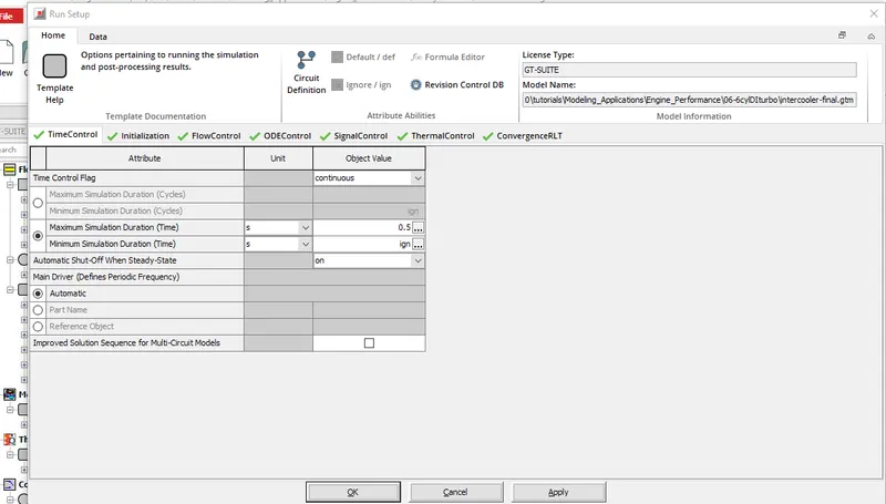
A.Time control flag:
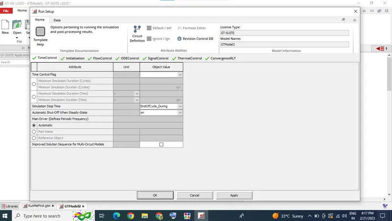
time control flag is the maximum simulation duration (cycles);
1. periodic (periodic indicates that the model contains at least one circuit which contains a periodic event (i.e. engine cylinder “cycle”) and therefore requires tracking of results with respect to angle over each cycle.)
2.continuous(continuous indicates that the simulation includes no periodic event, and therefore has no need to track results with respect to a cyclic angle.)
Time step and solution control:
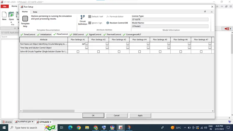
Name of the ' FlowControlExplicit', ' FlowControlImplicit', or ' FlowControlQS' reference object that can be used to define the numerical parameters for the explicit, implicit, or quasi-steady flow solver, respectively.
If there are no flow circuits in the model, starting in V2016 Build 2 this attribute may be set to “ign” or left blank (which is a rare exception to the normal requirement in GT-SUITE that all cells must be filled).
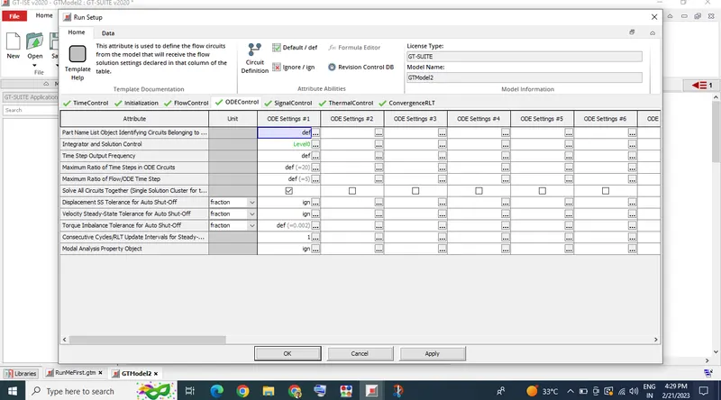
Integrator/Solver type:
Name of the ' DiffEqControl' reference object that can be used to define the numerical integrator and solution control.
Pre-created objects are available in the GT-SUITE Library, and the solver will use pre-defined values that have been found to work well for most simulations.
Additionally, the Circuit Definition Wizard can be used to determine which library object is best suited to each circuit cluster..
3. Explore intercooler tutorial and note down all settings of:
Run setup:
Run setup is used to define the simulation duration and time-controlling variables. The attributes in this folder must be defined for all simulations.
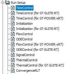
this run setup is consist of all the parameters in it. Time Control Flag Defines the global simulation type with regard to time.
In intercooler tutorial the run setup values are;
Advanced setup:
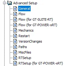
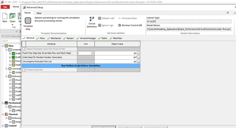
Generally in advance setup consists of
⊠ Import Parameter Data from External File?
External parameter files are most often used when the simulation will have input coming from some external source, very often in an automated manner, such as when a third-party optimization program is creating new combinations of inputs to run. Another example is when GT-SUITE is analyzing data from the laboratory, such as cylinder pressure data. In this case, the laboratory software can be programmed to automatically generate an external parameter file that includes information such as the engine speed and a filename where the measured cylinder pressure data can be found. The solver then runs automatically from command line with this data without need for user to manually modify the GT-SUITE model.
(⊠) External Parameter File Import Method:
Sets the method for importing the external parameter file specified in External Parameter Input File above. Syntax of these files is described in the help of the next attribute.
In intercooler tutorial the advance setup values are;
Plot setup:
Cycle and/or time plots may be requested by selecting the appropriate plot from the "Plot Options" folder within each part.
Each of these requests will result in a plot being stored. (This is not true when the specific plot requires a certain modeling option to be used in order to calculate the results that are to be presented in the plot. For example, plots of the pipe wall temperature versus radius will be made only when the wall temperature solver is used in the model.)
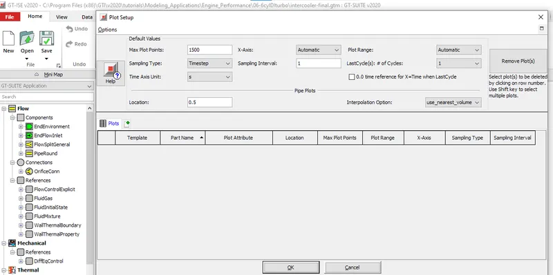
Plot Setup, which is found under the "Run" pull-down menu, gives the user a variety of options to change the way in which the plots are requested.
If no changes are requested, the Default Values, as specified in the top right corner of the Plot Setup Dialog, will be used. A button called "Remove Plot(s)" is available to remove unwanted plot requests from Plot Setup. All plots requested in individual parts will be stored regardless of whether the user chooses to use Plot Setup.
In intercooler tutorial the plot setup values are;
Output setup :
This folder can be used to optionally suppress certain GT-SUITE output in simulations where not all results are interesting. These options can be especially useful for models that are very large (i.e. many parts), span very long durations (i.e. many cycles), or have many cases, such as a DOE run.
In many of these larger models, the amount of data that would be saved if every output option is fully on would be prohibitively large, negatively affecting hard disk utilization and post-processing speed.
At the time a simulation is started, some checks are made to compare these data storage settings with the model size. If very large amounts of data storage are being requested, recommendations to change.
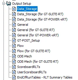
In intercooler tutorial the output setup values are;
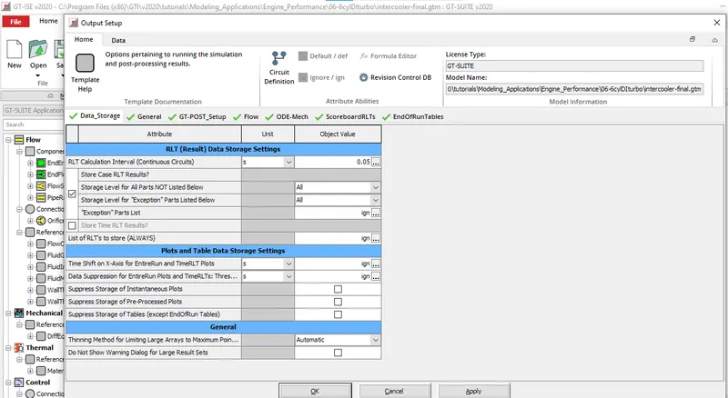
These are the setup details for a intercooler tutorial.
Problem:
Given:
- Diameter of cooler inlet and outlet pipe= 50 mm
- Length of the CAC= 1000 mm
- Inlet mass flow rate = 1200 kg/ h at 100 degC
- Outlet pressure 2 bar at 30 deg C
find:
- Calculate the Average heat transfer at Charge air cooler (CAC)
- Calculate pressure drop across CAC
solution:
the intercooler tutorial is changed as per the given and the simulation is carried out.
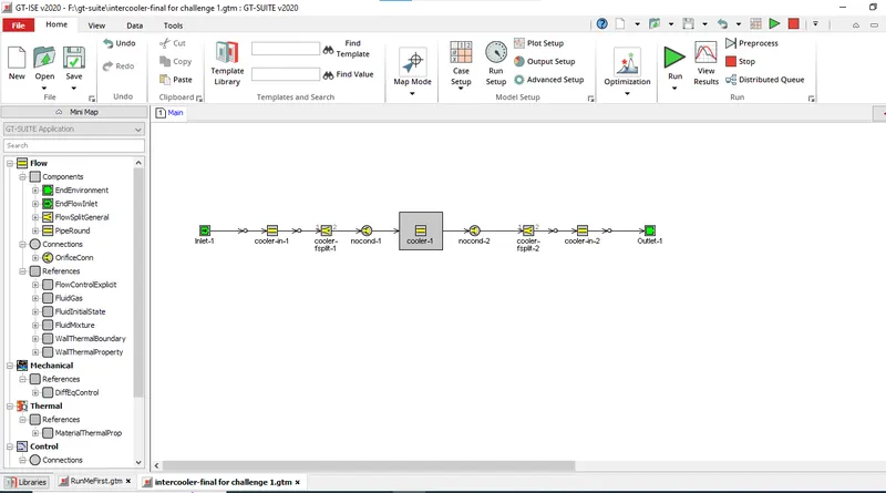
The pressure drop of the intercooler tutorial is ;
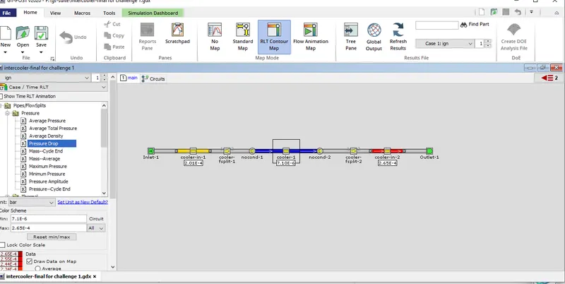
pressure drop across CAC is :7.095024e-6 bar.
Average heat transfer at Charge air cooler (CAC) of the intercooler tutorial is ;
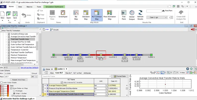
Average heat transfer at Charge air cooler (CAC) is : 6.2882495 kW.
CONCLUSION:
By this challenge the tool was explored well, and all the question asked in the challenge is answered correctly . the Average heat transfer at Charge air cooler (CAC) and the pressue drop of the cac is also dtermined with the help of GT-SUITE.
the GT-SUITE is explored well.