Week 1 : Exploring the GUI of GT-POWER
1. Explore the GUI SUITE and list down modules available with brief description?
GT Suite is the CAE simulation tool with capabilities and libraries aimed at a wide range of application and industries. It offers engineering functionalities ranging from fast concept design to detailed system or component analysis, deisgn optimization and root cause investigation.
Here are the industries which used GT-Suite
(1) On highway Vehicle
(2) Off- highway vehicle
(3) Marine and rail
(4) Industrial Machinery
(5) Aerospace
(6) Power Generation
Multi-Physics Platform
The foundatin of the GT-suite is a versatile multi-physics platform for constructing models of general systems based on many underlying fundamentals libraries:
(1) Flow library (Any fluid, gas or liquid or mixture)\
(2) Accoustics library (Both linear and non linear)
(3) Thermal library (all types of heat transfer)
(4) Mechanical library (kinematics, Multi-body dynamics, frequency domain)
(5) Electric and Electromagnetic library (Circuit, electromechanical devices)
(6) Chemistry Library( Chemical kinetics)
(7) Controls library (Signal Processing)
(8) Built-in 3D CFD and 3D FE (thermal and strcutural)
Modern software with unique capabilities
(1) Fusion of 1D and 3D simulation in one tool
(2) Imports solid models from CADto create 1D and 3D models
(3) Perform embadded 3D(CFD) and 3D FE thermal/structural modeling with all boundary conditions provided by the simulated surrounding complete system.
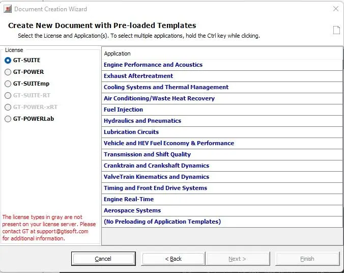
GT Suite Licence
Templates in GT suite
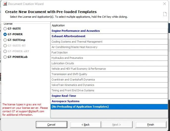
GT Power License
Templates in GT Power
GT Power EMP
Templates in GT Emp
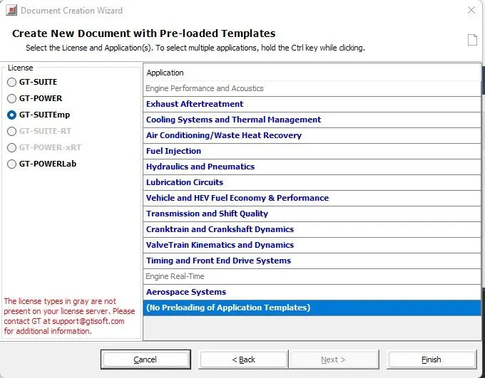
These all templates are used by different companies according to thier applications.
(2)
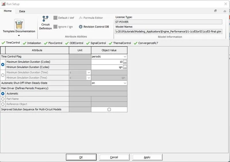
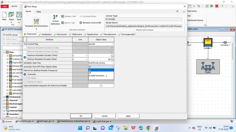
# Time Control Flag
Time control flag are of two type continous and periodic used according to case setup. For Engine application 'Time control flag is periodic' and for other applications
'continous option'. In max. simulation duration we define time for which setup will run to get converged solution.
# Time step and solution control
Time setup define duration of simulation results to converge. we can control time step and solution with option automatic shut off when steady state. with on option when solution converge it will automatically stop run setup.
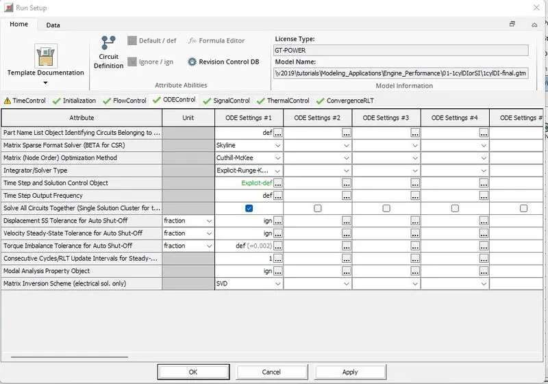
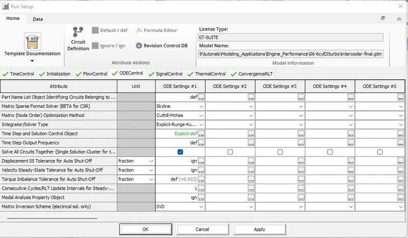
# Integrator/Solver type
There is lot of solver option like runga kutta method in below Run Setup option.
(3)
Explore intercooler tutorial

(Tutorial)
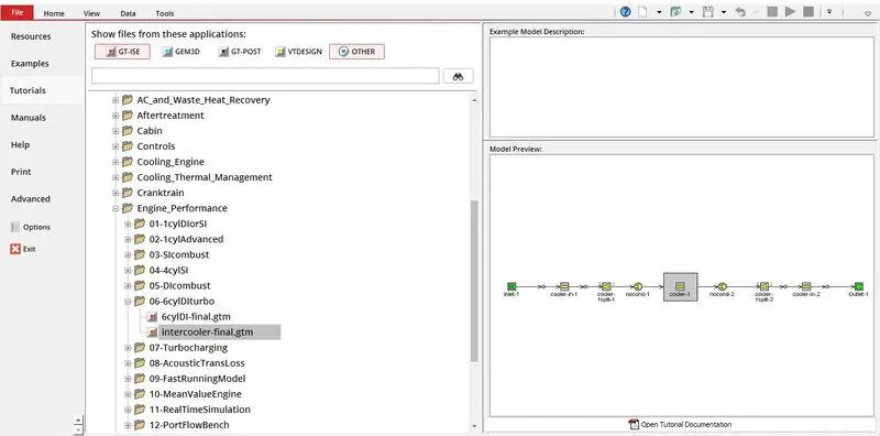
- Open the GT suite and click on Files and then select tutorials then select engine performance and then 6cyIDIturbo and then select the intercooler final. gym
- Thus the intercooler set up will pop up on the screen.
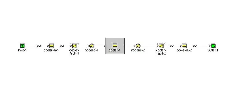
Define inlet and outlet diameter = 50mm
Length = 1000mm
Run Setup :

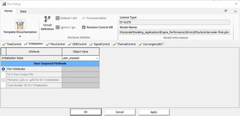
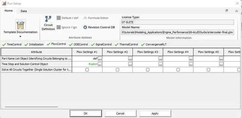
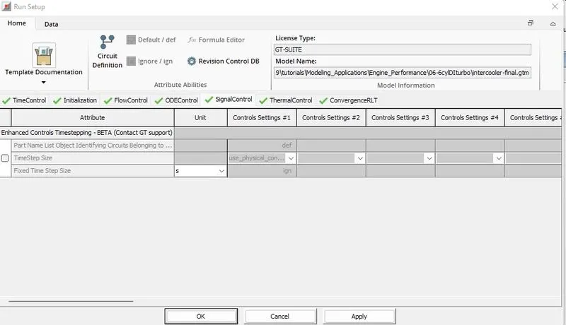
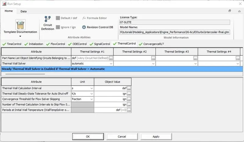
- In this module all the settings are done according to the results of our simulation to obtain the exactly results. It contains the different setups like Time Control,Initialization,Flow Control,ODE Control, Thermal Control, Convergence RLT.
- Each settings have a different attributes to run the simulation. we can go through all this sections detailed in the below images.
Time Control:
Initialization:
Flow Control:
ODE Control:
SignalControl:
Thermal Control:
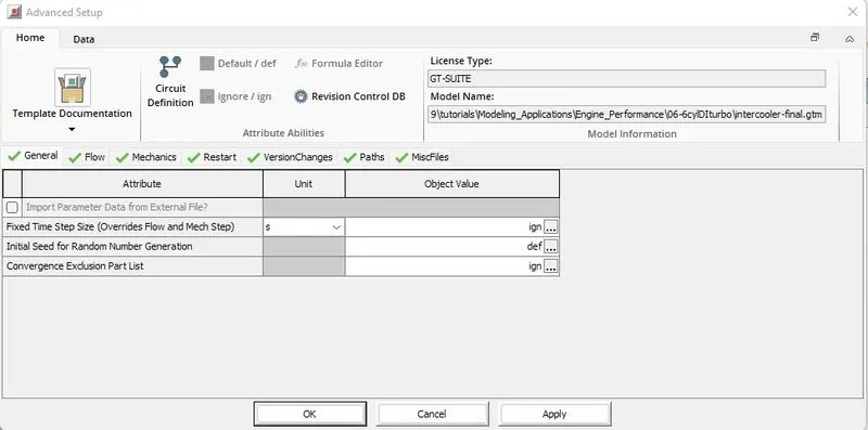
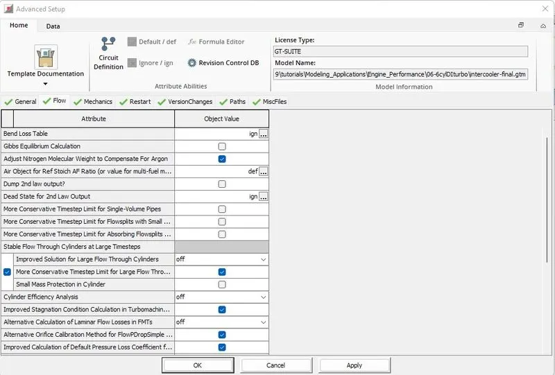
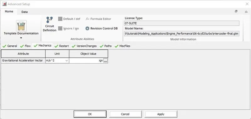
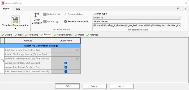
- Advanced Setup :

- Advanced setup also have the different Attributes and we can go through all the sections detailed in the below images. It contain the different Setups like
General,Flow,Mechanics,Restart,Version Changes, Paths,MiscFiles
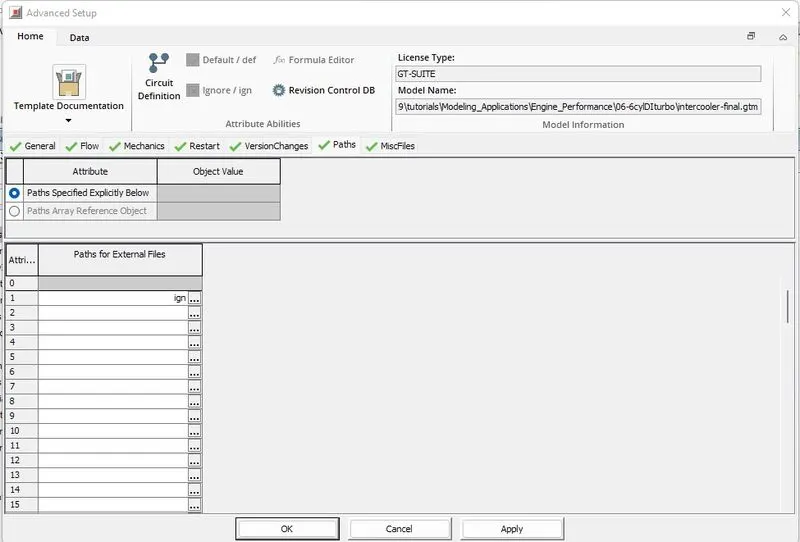
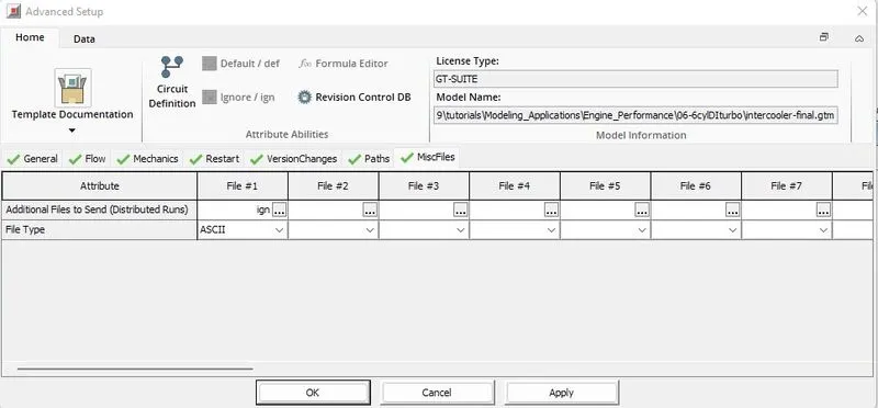
- Each settings have a different Attributes to run the simulation. We can go through all this sections detailed in the below images.
General :
Flow :
Mechanics :
Restart :
Version changes :
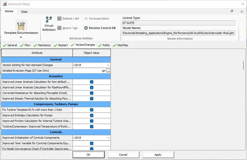
Paths :
MiscFiles:
- Plot Setup :

4. Problem :
Diameter of cooler inlet and outlet pipe = 50 mm
Length of the CAC = 1000 mm
Inlet mass flow rate = 1200 kg/h at 100 degC
Outlet Pressure 2 bar at 30 deg C
- Open the GT suite and click on Files and then select Tutorials then select Engine Performance and then 6ylDITurbo and then select the intercooler final.gtm
- Thus the intercooler set up will pop up on the screen.
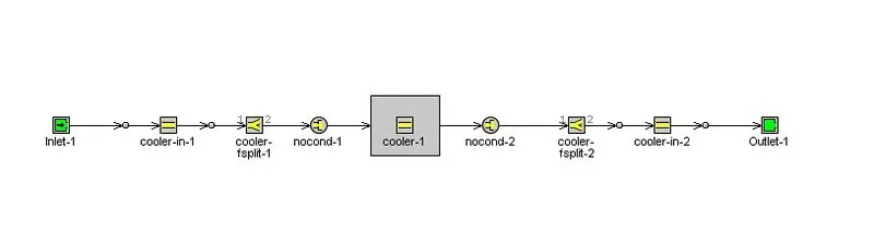
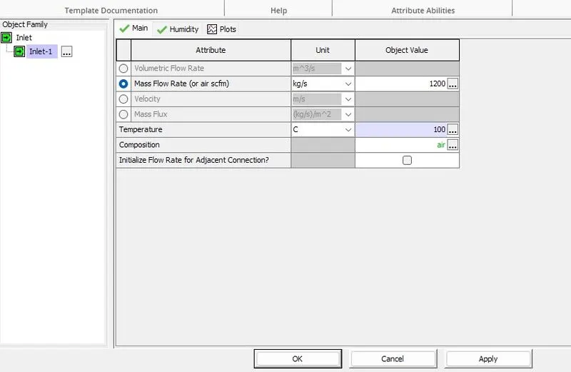
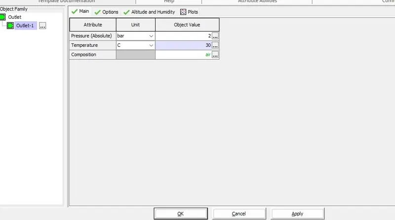
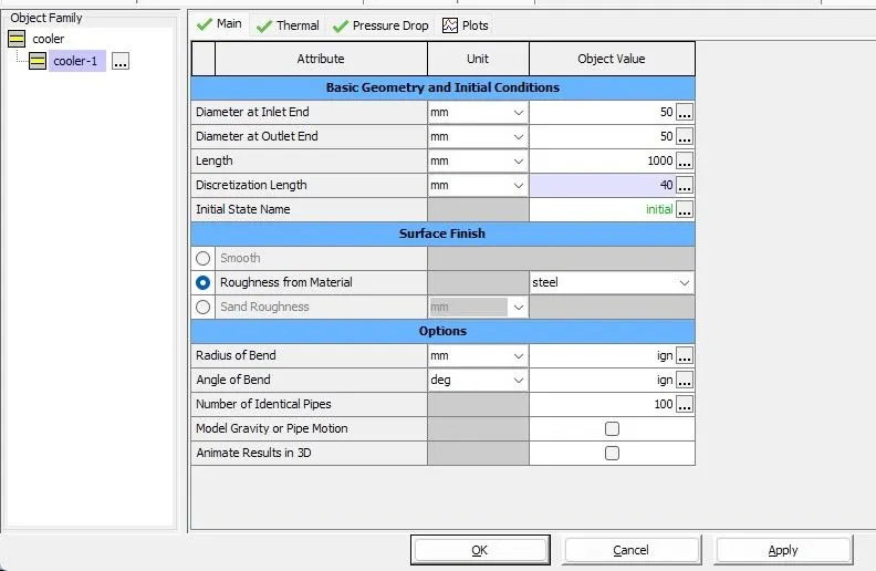
Run Setup
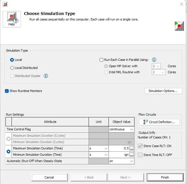
Click on Finish and GT post processor automatically OpenUp
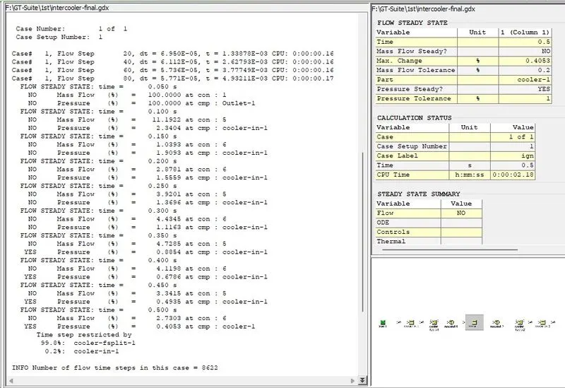
Results
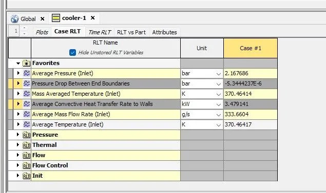
Average heat transfer to walls/ Average heat transfer at Charge air cooler (CAC) = 3.479141 kW
Pressure drop between End boundaries / Pressure drop across CAC = -5.3442 bar