Week 1 : Exploring the GUI of GT-POWER
Aim : Explore the GUI of GT-Suite and run the intercooler setup.
GT SUITE:
GT-SUITE is the industry-leading simulation tool with capabilities and libraries aimed at a wide variety of applications and industries. It offers engineers functionalities ranging from fast concept design to detailed system or sub-system/component analyses, design optimization, and root cause investigation.
The foundation of GT-SUITE is a versatile multi-physics platform for constructing models of general systems based on many underlying fundamental libraries:
- Flow library (any fluid, gas or liquid or mixture)
- Acoustics library (both non-linear and linear)
- Thermal library (all types of heat transfer)
- Mechanical library (kinematics, multi-body dynamics, frequency domain)
- Electric and Electromagnetic library (circuits, electromechanical devices)
- Chemistry library (chemical kinetics)
- Controls library (signal processing)
- Built-in 3D CFD and 3D FE (thermal and structural)
Different modules available in GT SUITE are:
GT-AUTOLION : GT-AutoLion is the industry-leading lithium-ion battery simulation software used by cell designers and OEMs to predict performance, degradation, and safety for any Lithium-ion cell. It predictively models the electrochemical processes within Lithium-ion cells using a fast and reliable, electrochemical, physics-based approach.
GT-SUITE-RT: GT-SUITE-RT is supplied as a Simulink S-function, and the GT models are easily integrated into Simulink control system models for desktop simulation.
GT-TAITHERM: GT-TAITherm is a thermal and infrared signature modeling tool solving 3D conduction, convection and multi-bounce radiation.
GT-CONVERGE: GT-CONVERGE is a 3D CFD module which complements GT-SUITE and advances your plant and system level simulations. Importantly, it empowers non 3D-CFD experts, through features like autonomous meshing and dedicated easy-to-use simulation setup.
Different modules and there application:
GT-Suite :
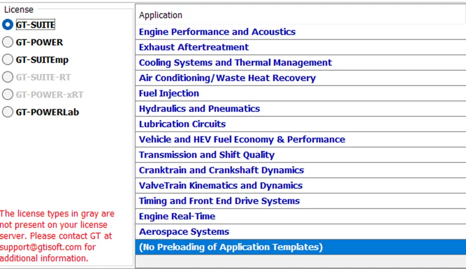
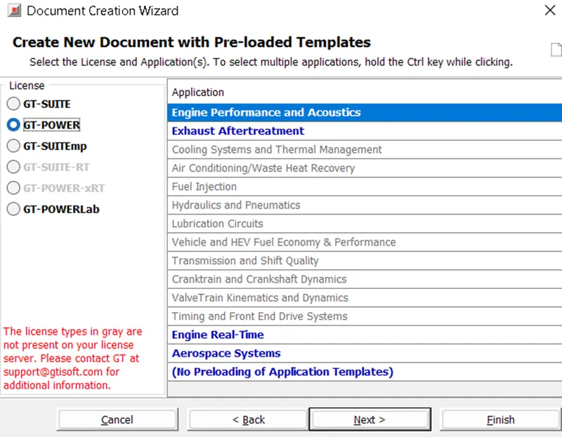
GT-Power:
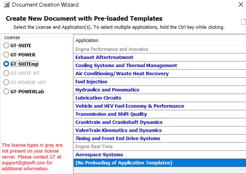
GT-SUITEmp:
GUI of GT-Suite:
Run setup:
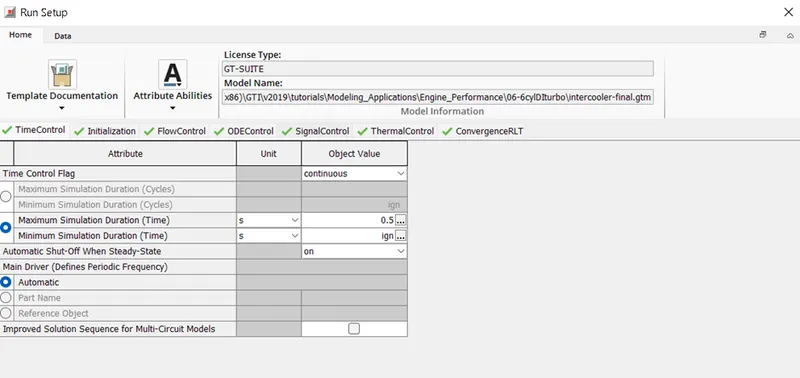
In Run setup we have Time control flag.
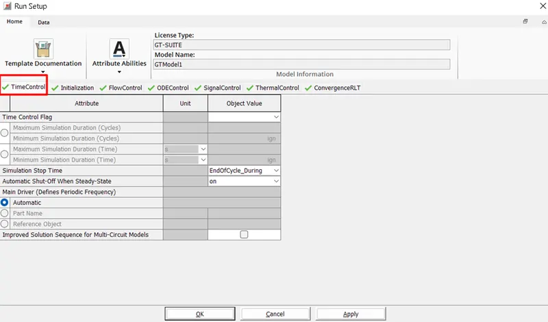
Flow control:
Under Flow control we have Time step and Solution Control Object

Ode Control:
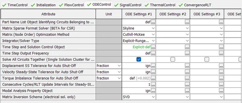
We can find Integrator/Solver Type in ODE control, here we can select different solver types.

Intercooler Tutorial:
Import the Intercooler Tutorial. File > Tutorial > Modelling Applications > Engine_Performance > 06-6cylDiturbo > intercooler-final.gtm
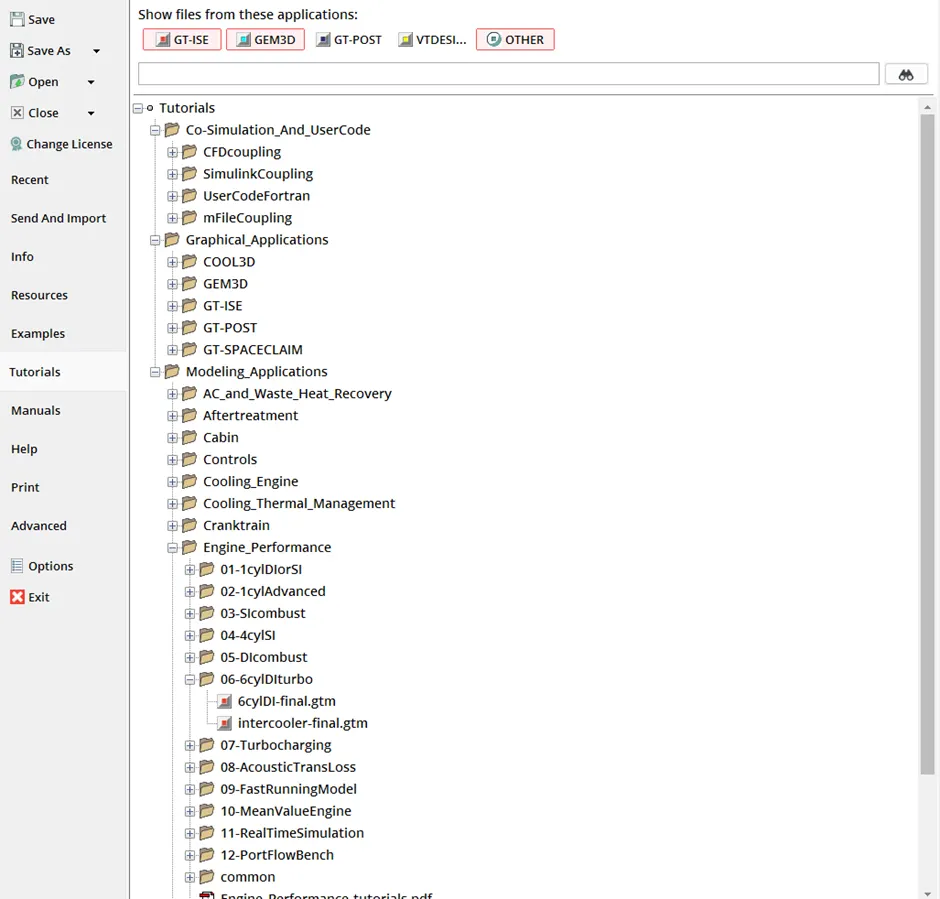
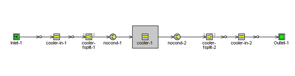
Different Setups under Intercooler Tutorial are:
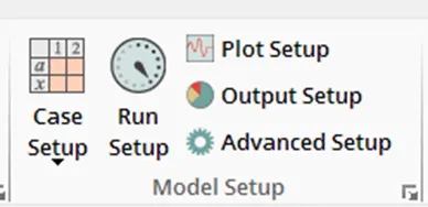
Run Setup:
Under Run setup we have following settings:
- TimeControl
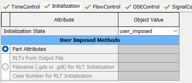
- Initialization
- FlowControl
- ODEControl
- SignalControl
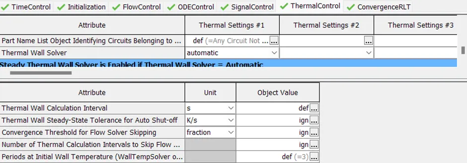
- ThermalControl
- COnvergenceRLT
TimeControl:
Initialization:
FlowControl:

ODEControl:
SignalControl:

ThermalControl:
COnvergenceRLT:
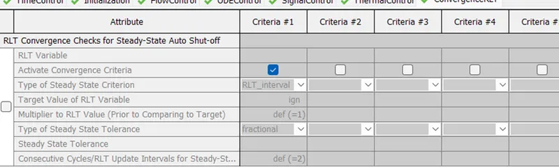
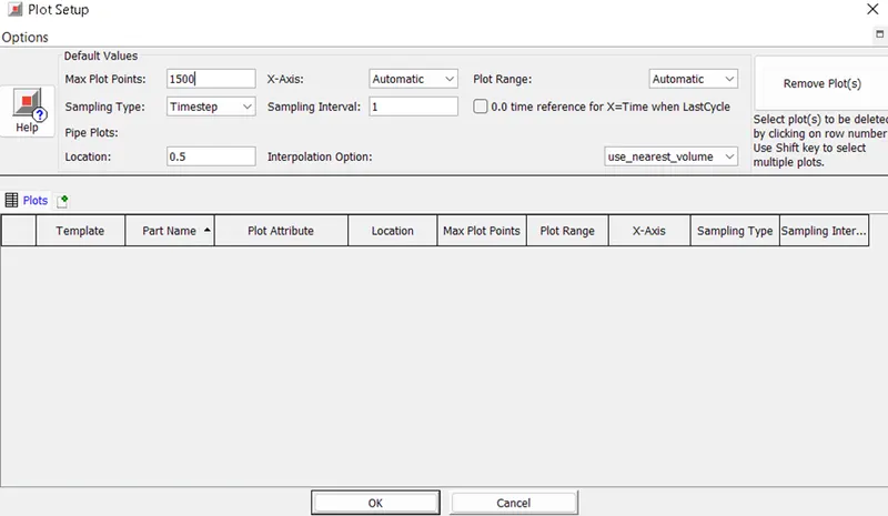
Plot Setup:
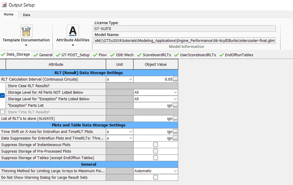
Output Setup:
We have following settings under Output Setup;
- Data_Storage
- General
- GT_POST_Setup
- Flow
- ODE-Mech
- ScoreboardRLTs
- UserScoreboardRLTs
- EndofRunTables
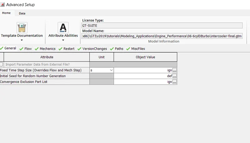
Advanced setup:
We have following settings under Advanced Setup:
- General
- Flow
- Mechanics
- Restart
- VersionChanges
- Paths
- MiscFiles
Intercooler Problem:
Problem Statement:
Given:
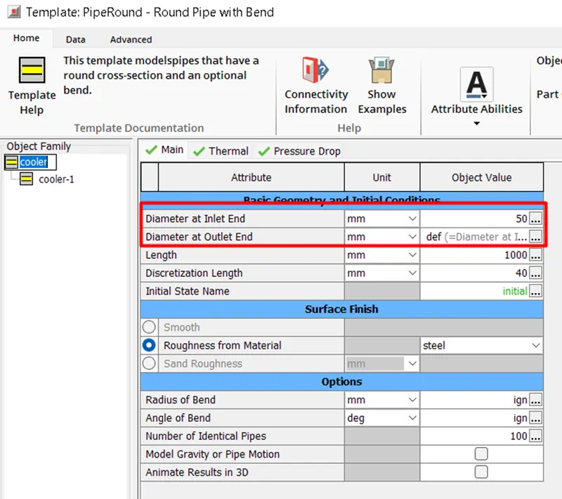
Diameter of cooler inlet and outlet pipe= 50 mm
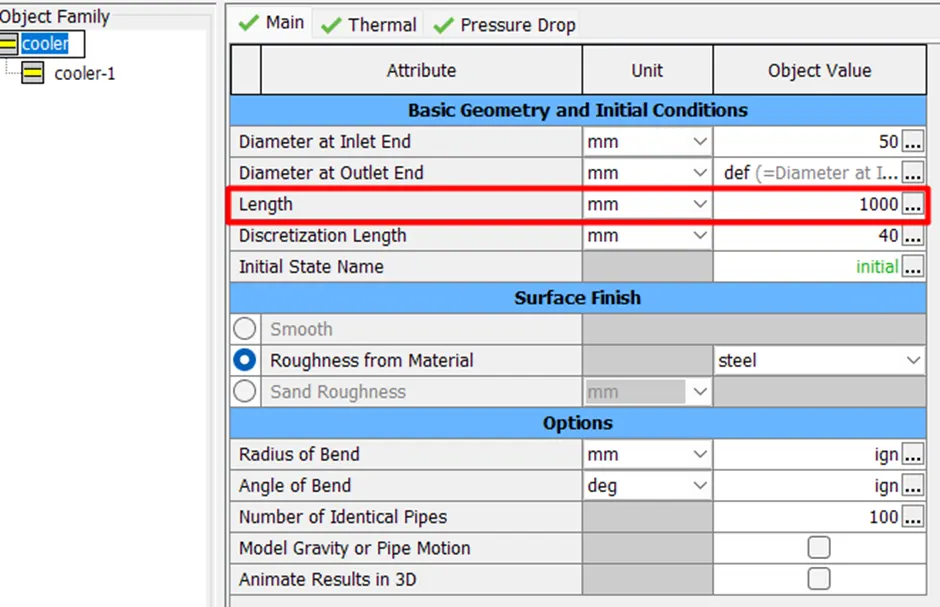
Length of the CAC= 1000 mm
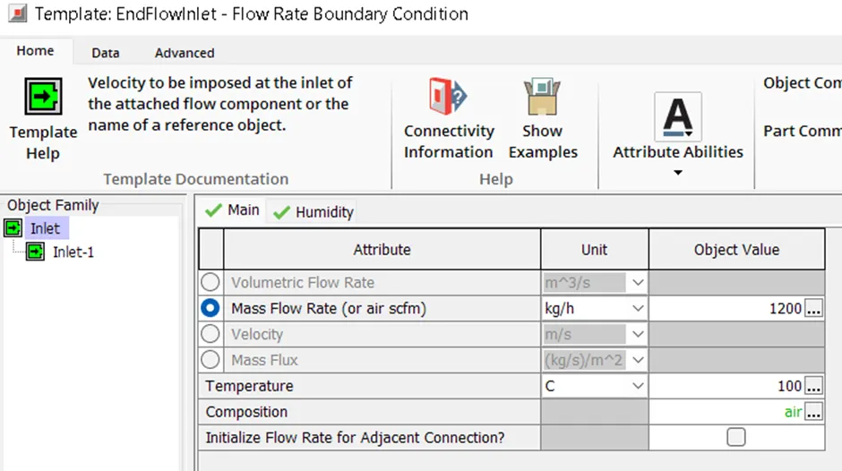
Inlet mass flow rate = 1200 kg/ h at 100 degC
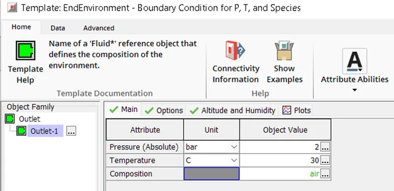
Outlet pressure 2 bar at 30 deg C
Objectives:
Calculate the Average heat transfer at Charge air cooler (CAC)
Calculate pressure drop across CAC
Procedure:
Setting the Diameter of cooler inlet and cooler outlet pipes:
Set the diameter of cooler inlet and cooler outlet pipe as 50mm
To change the diameter of i Flow > Components > PipeRound > cooler
Setting the length of CAC:
Change the length of length to 1000mm
Setting inlet and outlet conditions:
Inlet mass flow rate = 1200 kg/ h at 100 degC
Outlet pressure 2 bar at 30 deg C
Inlet:
Outlet:
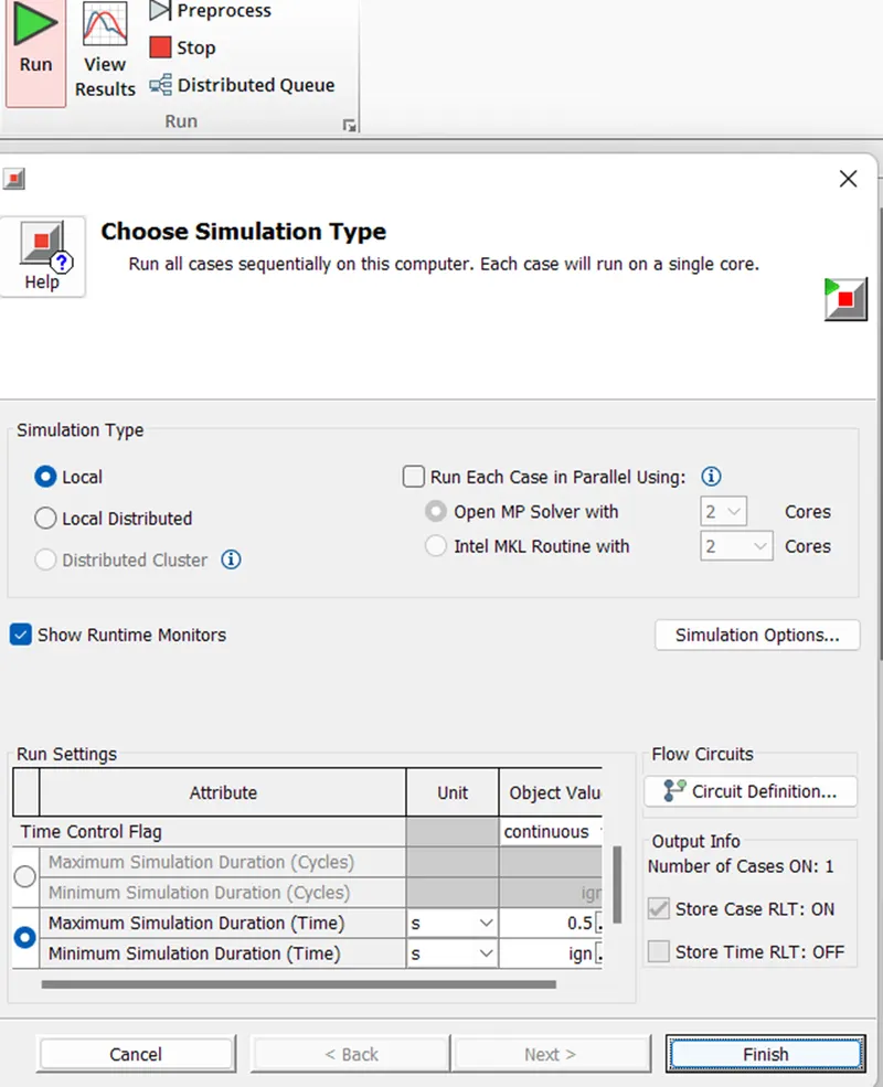
After setting up the values Run the setup:
Results:
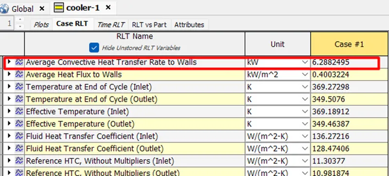
Average heat transfer of CAC cooler: 6.29 KW

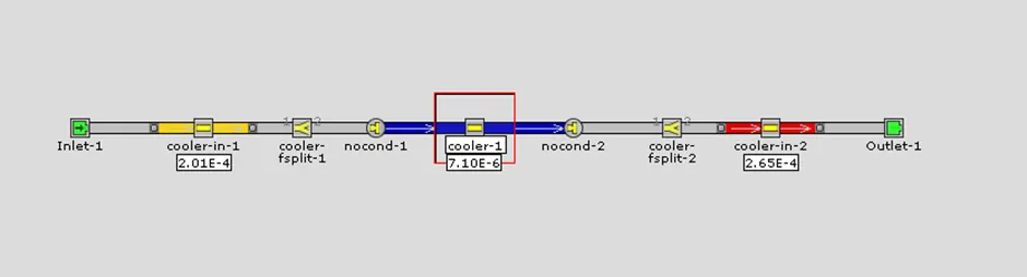
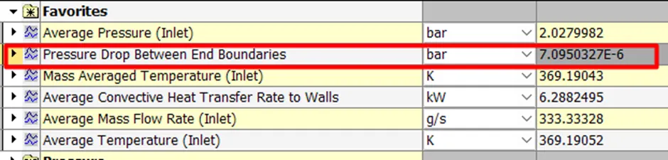
Pressure drop across CAC: 0.083 bar
Conclusion:
- Intercooler simulation is done. The Heat transfer and Pressure drops are calculate
