Week 1 : Exploring the GUI of GT-POWER
1. Explore the GUI of GT SUITE and list down modules available with a brief description.
Modules in GT Suite are as follows:
a. COOL 3D
The Cool 3D feature is a CAD-based pre-processing tool with GT-COOL to simulate 3D modules integrated with 1D cooling circuits. It is used to comprehend the airflow around/through stacked heat exchangers, fans and engine blocks.
b. GEM 3D
GEM 3D is a feature that is used to build complete exhaust or intake systems including multiple mufflers, pipes and airboxes.
c. GT ISE (Integrated )
It is the main interface where models are built and simulation are launched. It is an environment where all the elements are brought into the map and connected together linking the entire model.
c. GT POST
It is used to view and manipulate the results obtained from the simulation. GT POST is used to generate the 2d and 3d plots, combining the different test cases in the single plots and data.
e. VT DESIGN
VT design feature is used to design valvetrain and cam. It can also be used to create cam design/profiles, dimensions, valvetrain mechanism can be run and viewed directly from the VT design interface.
f. GT SPACECLAIM
GT-SPACECLAIM uses built-in translation tools to import common CAD format into GT-SUITE. Simplifying geometry to prepare a model for simulation and extracting the inner/fluid core of solid models are some of the application.
2. Locate the following settings:
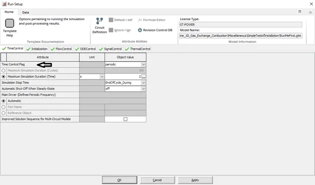
Time control flag
This feature can be accessed through Runsetup>Time control
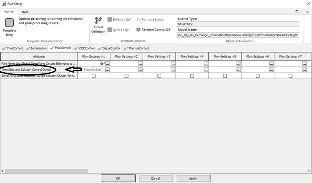
Time step and solution control
Go to
Run Setup>Flow control> Time step and solution control
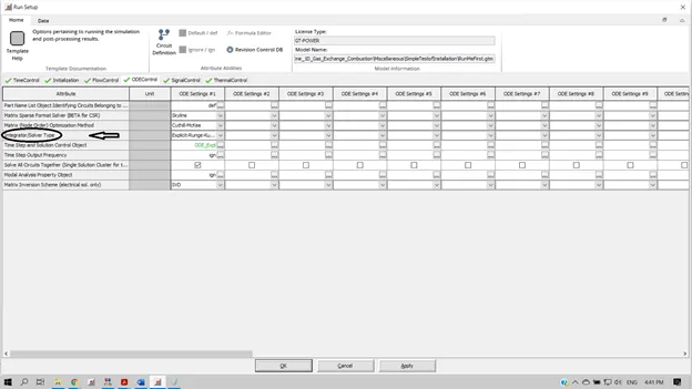
Integrator/Solver type
Go to
Run Setup>ODE control>Integrator/solver type
3. Explore intercooler tutorial and note down all settings of:
Run Setup
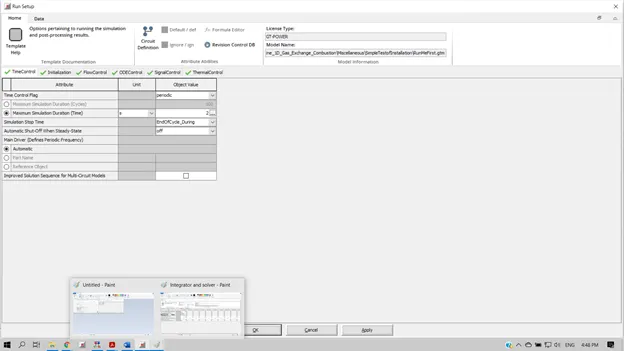
In Run setup, different attributes can be chosen for changing the time interval such as periodic or continuous, time step solution etc as shown below.
- Time control
- Initialization
- Flow control
- Signal control
- ODE control
- Thermal Control
- Convergence RLT
Advanced setup
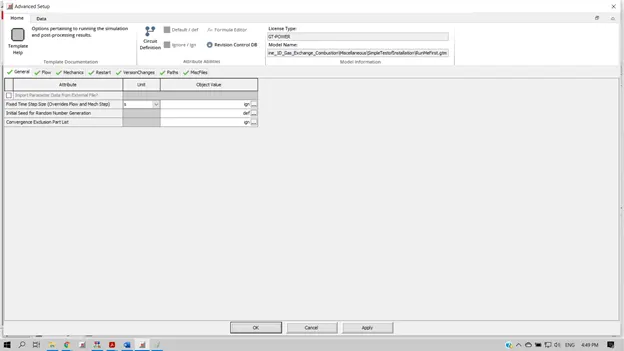
Similar to run the setup, the advanced setup also contains different attributes
- General
- Flow
- Mechanics
- Restart
- Version changes
- Paths
- Misc Files
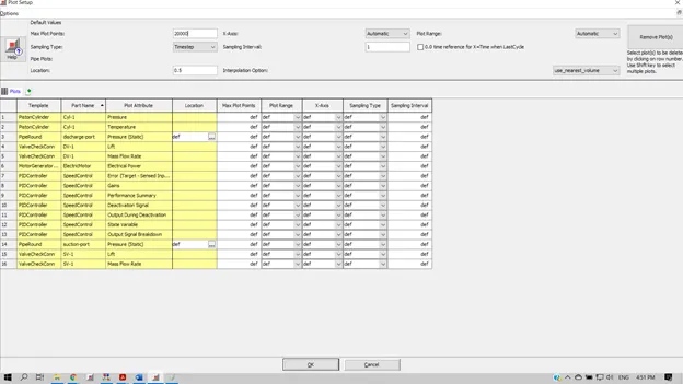
Plot setup:
Output setup:
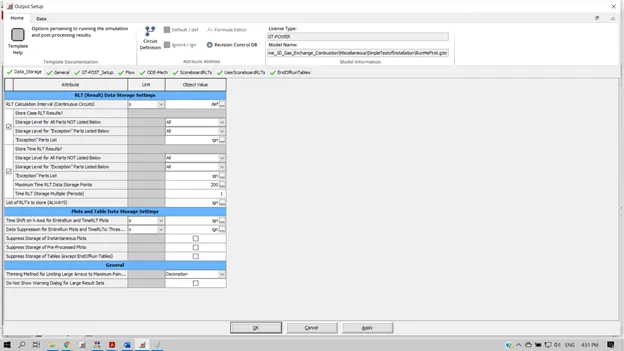
Output setup consists of the following options
- Data storage
- General
- GT-POST setup
- Flow
- ODE MECH
- ScoreboardRLTs
User ScoreboardRLTs
- EndofRunTables
4. Problem
Data Available
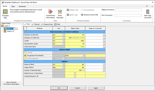
- The diameter of the cooler inlet and outlet pipe is 50 mm.
- Length of the CAC = 1000 mm
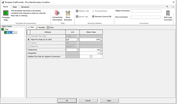
- Inlet mass flow rate = 1200 kg/h at 100 deg celcius
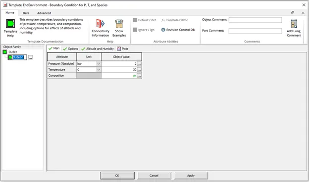
- Outlet pressure = 2 bar at 30 deg Celcius
Compute
1. Calculate the total heat transfer at the charge air cooler (CAC)
2. Calculate pressure drop across charge air cooler
Procedure to access intercooler
a. Entering mass flow rate data at the inlet
b. Entering inlet and outlet diameters
c. Entering outlet pressure
After plugging all the required data, now press RUN to solve the problem and visualize the results using GT-POST
Results :
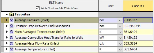
-> Total heat transfer at CAC = 8.43 kW
-> Pressure drop across CAC = 0.0245 bar