Week 1: Channel flow simulation using CONVERGE CFD
AIM: The main objectives of the current project are:-
1) To setup the CFD simulation case for flow through a channel in CONVERGE.
2) To generate and analyze plots and contours for pressure, velocity, mass flow rate, and cell count.
3) To run the case for 3 different mesh sizes and compare the results.
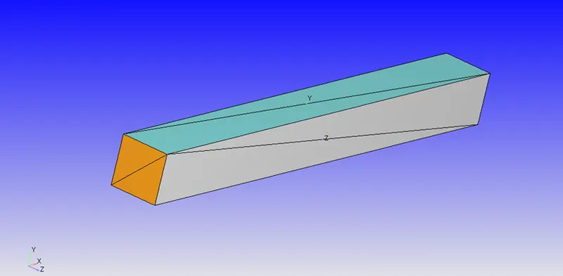
GEOMETRY: A geometry was created in converge for channel flow with the following dimensions.
Length in X direction=0.1m
length in Y direction=0.01m
length in Z direction=0.01m
Case Setup: Following is the case setup tree in converge. It is the case setup tool in converge where we set our input parameters required for the flow.
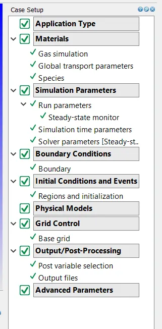
1) Application type: The application type is chosen as "Time-based" as this is a general flow.
2) Materials: In the materials tab we checked the Gas simulation, Global Transport Parameter, and Species boxes.
a) Gas simulation: Default values were used.
b) Global transport parameters: Here also, default values are used.
Turbulent Prandtl no.=0.9
Turbulent Schmidt no.=0.78
c) Species: In the species, O2 and N2 are chosen as we have assumed that air is flowing through the channel.
3) Simulation parameters:
a) Run parameters: Here, the solver is a "steady-state solver" and the simulation mode is "Full Hydrodynamic". As it is a simple geometry, there is no need to run the simulation in "No Hydrodynamic" mode to test the case setup. The gas flow solver is "Compressible". The "Steady-state monitor" is turned on and "Use Shared Memory" is turned off in the Miscellaneous tab. All other parameters are default.
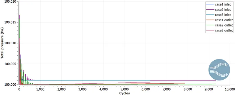
And in the steady-state monitor, the minimum number of cycles to be executed was chosen to be 5000. And the parameters to be converged were avg. temp, total pressure, and average density.
b) SImulation time parameters: Following values were used.
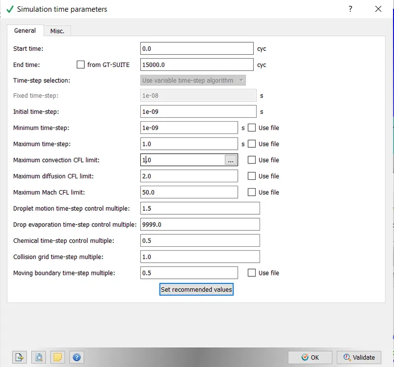
C) Solver parameters: pressure-based solver was chosen, and the maximum convection CFL limit at the final stage was set to be less than 1. All the other parameters were default.
4) Boundary conditions: these are as follows.
-Inlet: Boundary type- inflow, Total Pressure- 100001 Pa, Temp- 300K
-Outlet- Boundary type- outflow, Total Pressure- 100000 Pa, Temp- 300K
-Top & Bottom- Boundary type- wall with stationary wall motion and fixed surface movement.
-Front and Back- 2D boundaries.
5) Regions and initialization: here boundaries are assigned to the region.
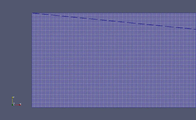
CASE 1- Grid size Dx=Dy=Dz= 1e-4m
CASE 2- Grid size Dx=Dy=Dz= 1.5e-4m
CASE 3- Grid size Dx=Dy=Dz= 2e-4m
RESULTS AND DISCUSSION:
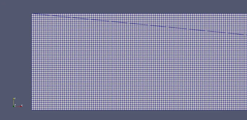
1]MESH-
CASE-I
CASE-II
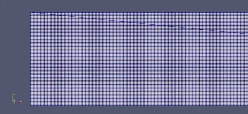
CASE-III
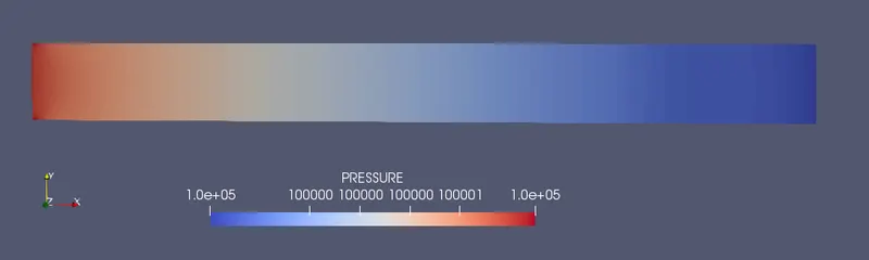
2] Pressure contours:
Case-I
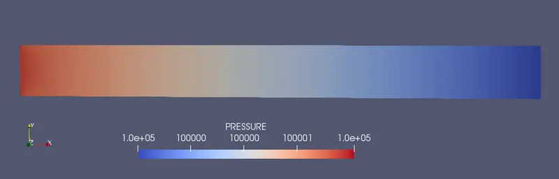
Case-II
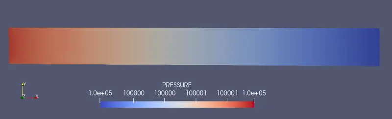
Case-III
PRESSURE ANIMATION:
3] Velocity Contours:
CASE-I
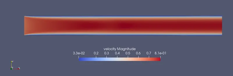
CASE-II
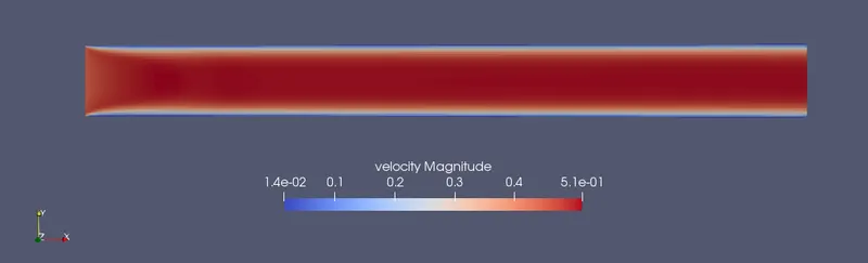
CASE-III
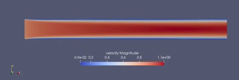
VELOCITY ANIMATION:
4] Total cell count:
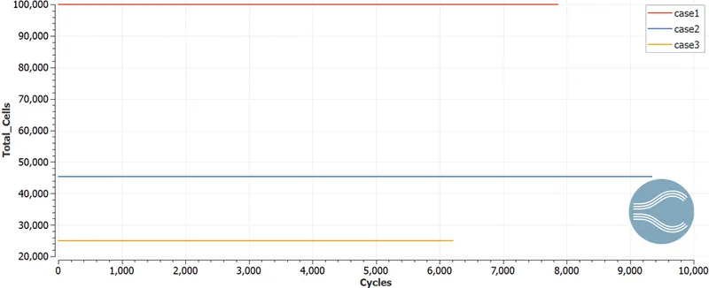
The total cell count for case 1 is 100000, for case 2 it is 45420 and for case 3 it is 25000 cells.
5] Total Pressure curves:
CASE-I
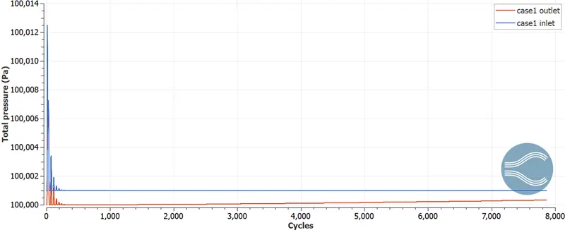
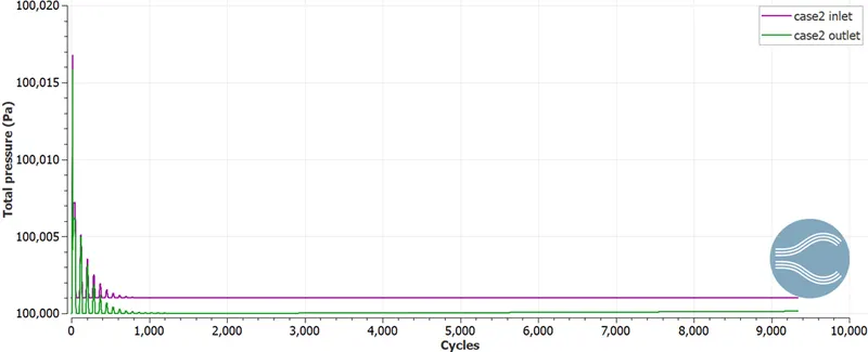
CASE-II
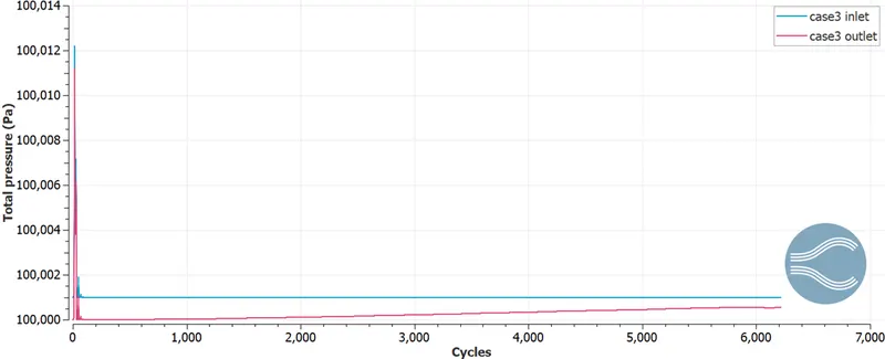
CASE-III
Combined pressure plots:
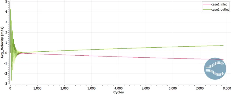
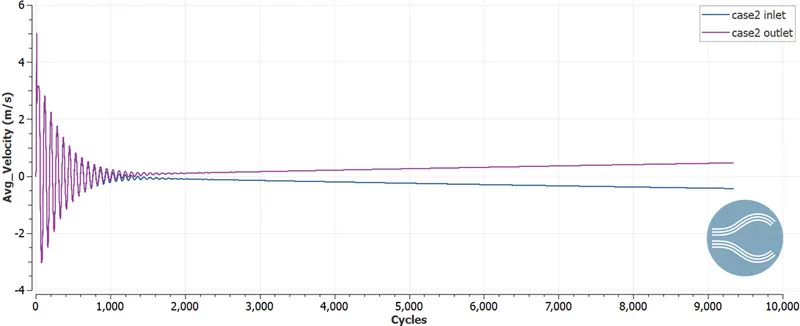
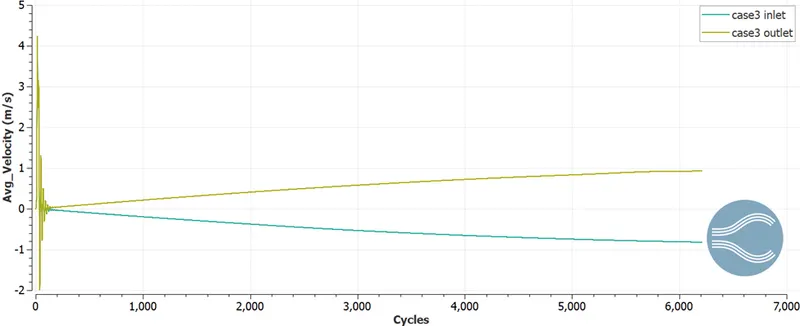
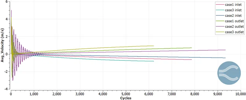
6] Average Velocity plots:
CASE-I
CASE-II
CASE-III
Combined plots
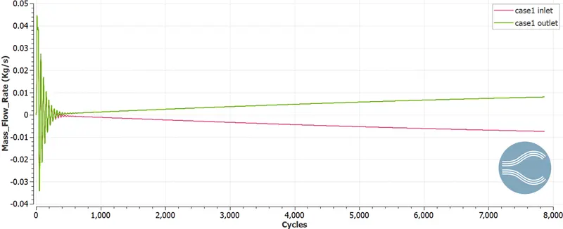
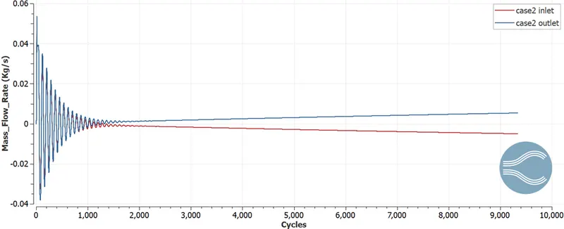
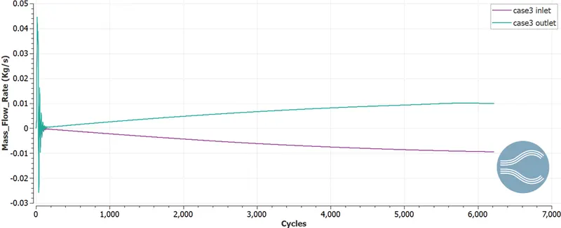
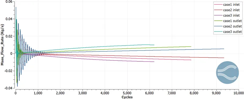
7] Mass Flow Rate plots:
CASE-I
CASE-II
CASE-III
Combined plots:
CONCLUSIONS:
1) The simulation was run for three different mesh sizes.
2) It is clear from the pressure contour that the flow is driven by the pressure difference.
3) As the mesh size gets finer, the simulation time required increases but the solution gets better.