Week 1: Channel flow simulation using CONVERGE CFD
AIM
Channel flow simulation using CONVERGE CFD
PRINCIPLE
Whenever a fluid flows inside a pipe, the wall of the pipe imparts resistance to the fluid flow. This resistance flow result in creating a no slip layer just above the wall.
⦁ The above figure shows the fully devoloped flow of fluid in the pipe.
⦁ We assume the fluid to flow as different layers
⦁ Just before the fluid enters the pipe all the layers of the fluid is assumed with a constant velocity
⦁ As the Fluid enters the channel, wall of the channel imparts resistance to the fluid flow and cause the layer of fluid just above the wall to cease the movement
⦁ As the flow progresses. The layer above the wall imparts a parts of its resistance to a layer of flud above it. This process continues to obtain a layer called as boundary layer
⦁ Boundary layer is the thin layer of fluid in the immediate vicinity of a bounding surface formed by the fluid flowing along the surface. The fluid's interaction with the wall induces a no-slip boundary condition (zero velocity at the wall).
⦁ The flow velocity then monotonically increases above the surface until it returns to the bulk flow velocity. The thin layer consisting of fluid whose velocity has not yet returned to the bulk flow velocity is called the velocity boundary layer.
CASE SETUP
OBJECTIVE
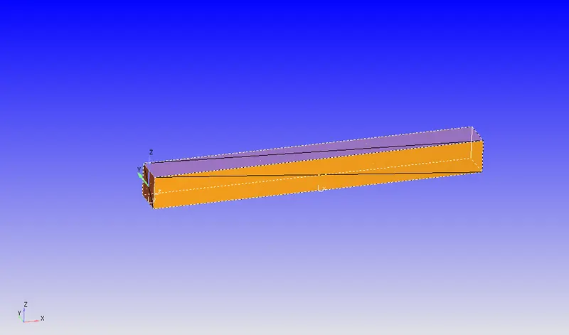
Length of channel in the x axis=0.1 m
Length of channel in y axis=0.01
Length of channel in the z axis= 0.01
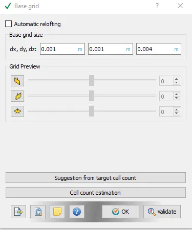
Base grid size
dx=4e-4
dy=4e-4
dz=4e-4
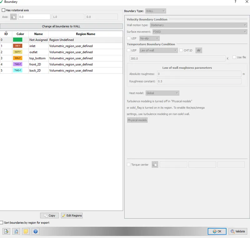
BOUNDARY CONDITIONS
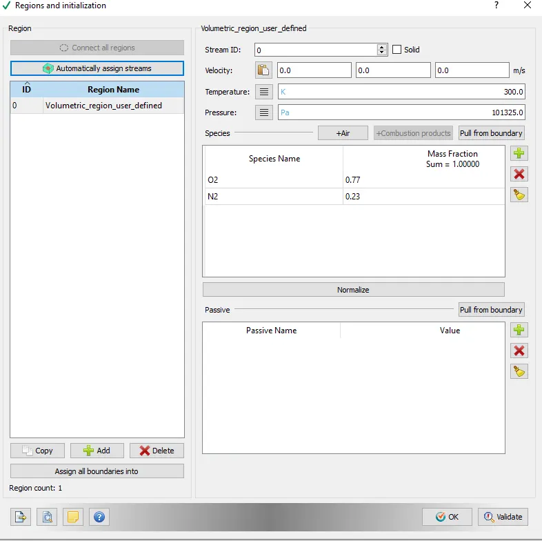
REGIONS
BASE GRID SETUP
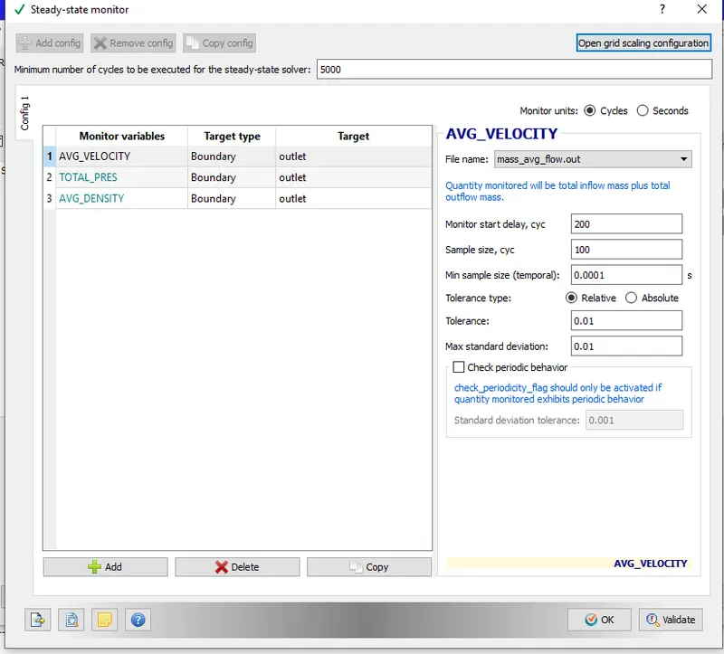
STEADY STATE MONITOR
RESULTS
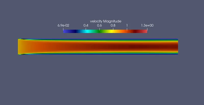
VELOCITY PROFILE
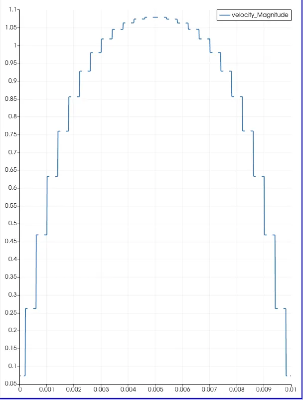
VELOCITY PROFILE ALONG Y AXIS AT X=0.09 M
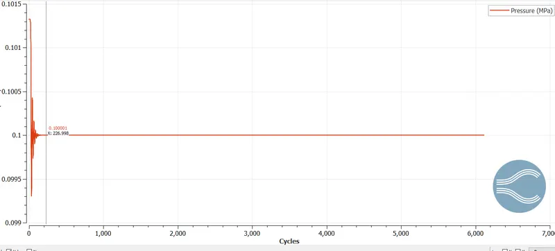
PRESSURE
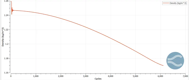
DENSITY
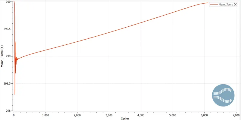
MEAN TEMPERATURE
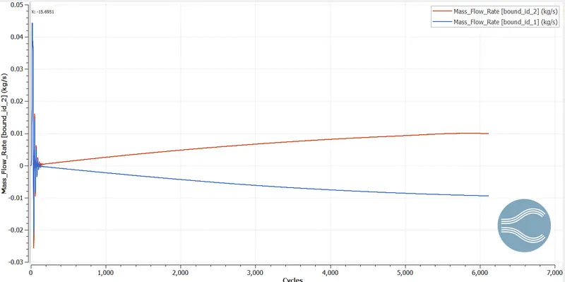
MASS FLOW INLET