Week 1 Challenge
Truss type reasoning
Out of the two through type truss systems shown below, which is the most efficient in carrying gravity load? Reason it out.
We can clearly see that the Truss A is a Pratt Truss and Truss B is a howe truss.
Pratt Truss -
It is one of the common forms of the truss and is made up of vertical and diagonal members that forms an N shape or pattern. The diagonal
members are arranged so that they only develope tensile forces. As such, they can be designed to resist axial tension only. avoiding the
need for a compression buckling analysis. The vertical members in a Pratt Truss develope compression forces. This means they will
typically be more robust and capable of resisting buckling.
It is composed of alternate vertical and inclined members.
It has diagonal members that slant down towards the middle.
Howe Truss -
It is essentially the opposite of pratt trusses in terms of geometry. In fact looking at a pratt truss upside - down will visiuallize a howe truss
of sorts. The entire structure is still relatively the same, but the diagonal braces are now occupying the unoccupied joints. This switch in this
position of the diagonal members has a very important effect structurally.
It consist of alternate vertical adninclined members.
It has diagonal members that slant down away from the middle.
Pratt trusses have their vertical members in compression and diagonal members in tension upon the applivation of gravity loads at the joints
of the top chord. For howe trusses, the reverse become true as diagonal members are now in compression, while the vertical loads are in tension.
Hence that Pratt Truss ( Truss A ) is more efficent in carrying load gravity.
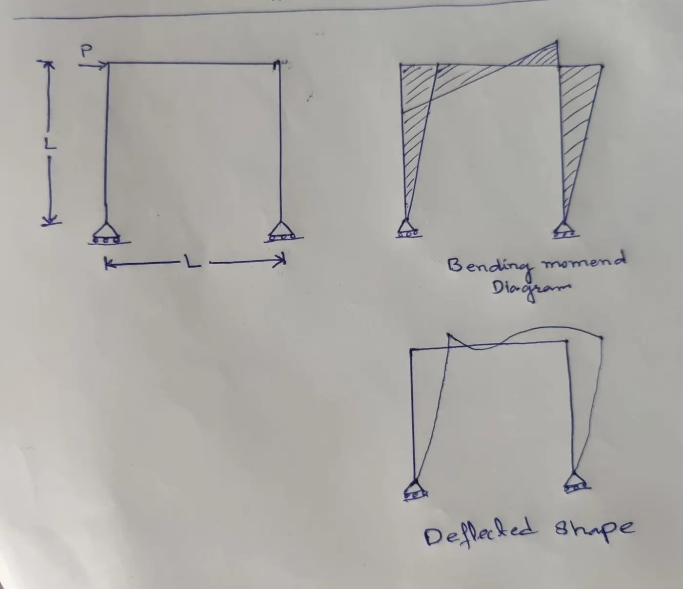
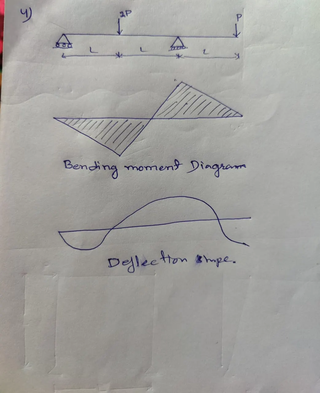
2. Deflection shape & Bending Moment Drawing (Qualitative approach)
For the beam & Frame below draw deflected shape and bending moment drawing. (Qualitative approach). E & I are constants.
1) 
2,3)
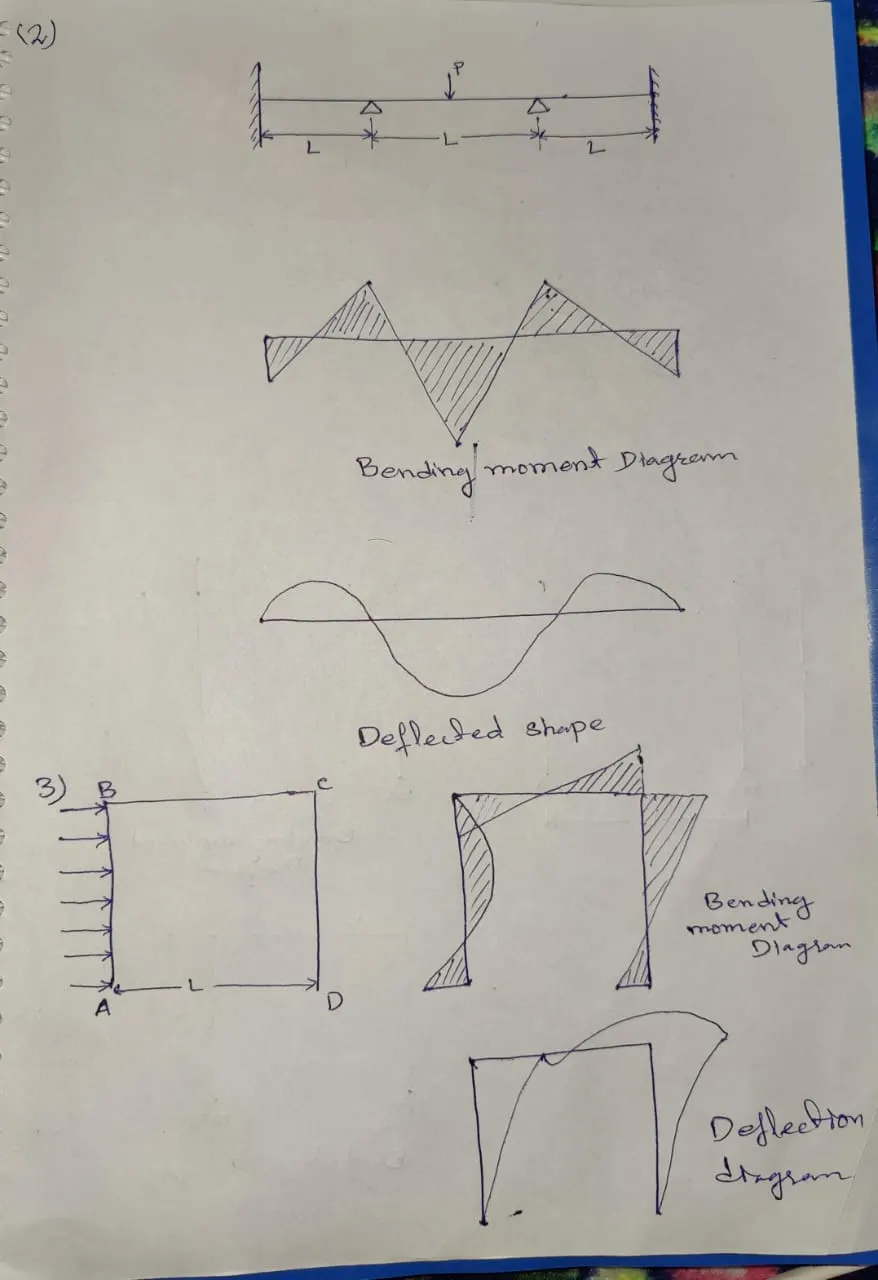
4)
3. Determine MOI, Weight, C/S area of sections below
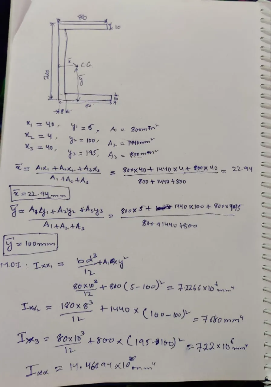
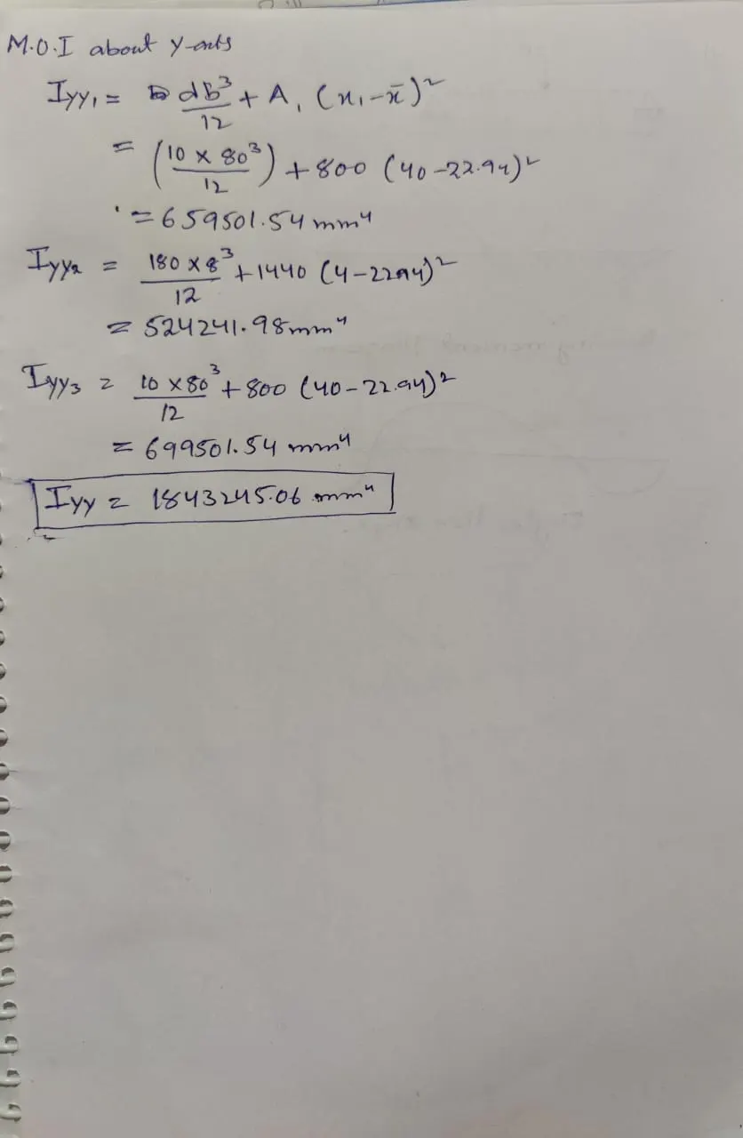
I section
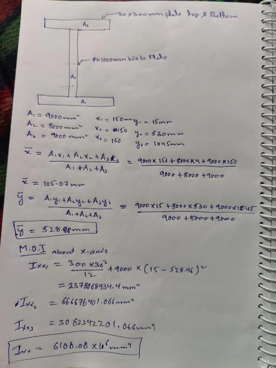
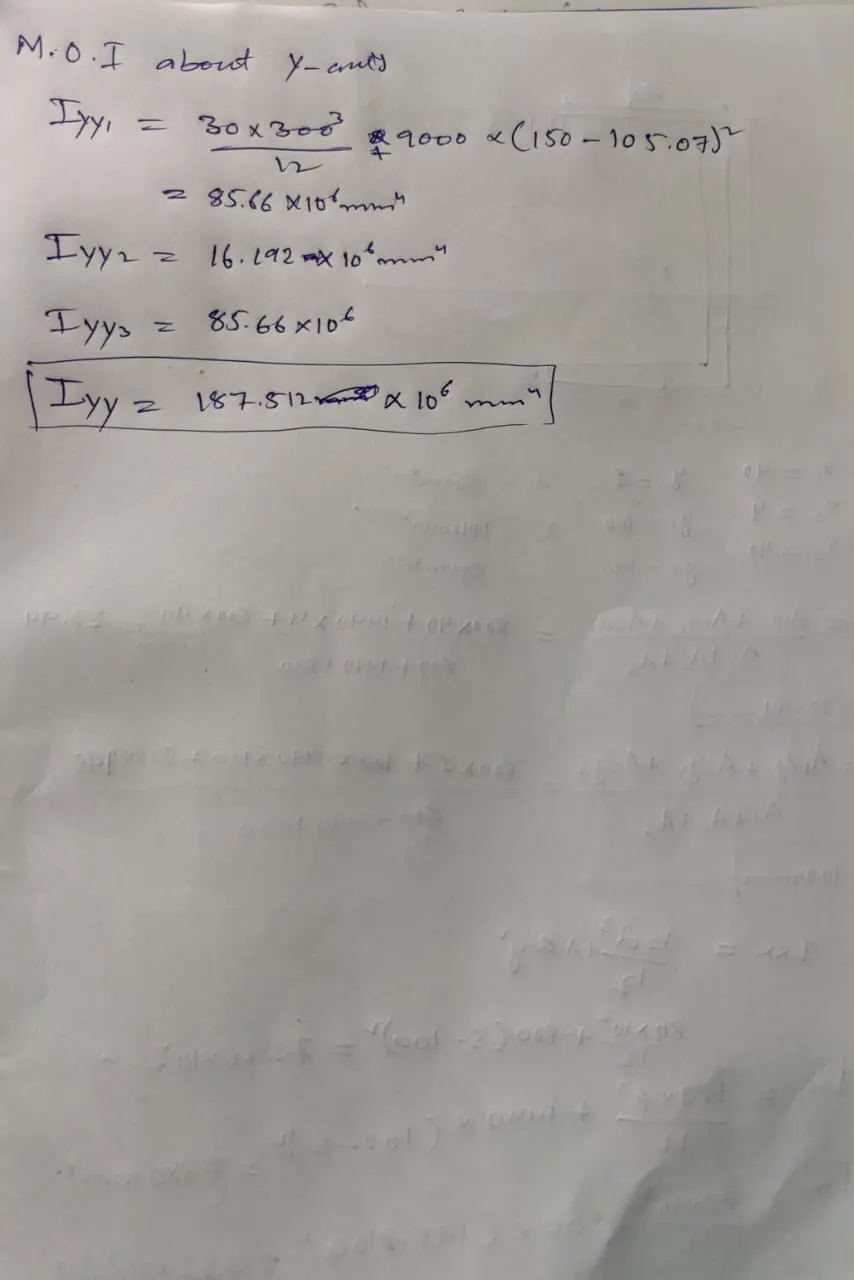
4. Load calculation problem
For the floor framing below, Calculate the load on interior beam, Exterior beam, Interior Girder and exterior girder having Floor Load of 10kN/m2
Floor Load - 10kN/m2
Tributary width of exterior girder - 0.5(0+8)= 4m
Tributary width of interior girder - 0.5(8+8)= 8m
Tributary width of exterior beam - 0.5(0+2)= 1m
Tributary width of interior beam - 0.5(2+2)= 2m
Load on beam = Tributary width x floor load
Load on exterior girder = 4 x 10 = 40 kn/m
Load on beam interior girder = 8 x 10 = 80 kn/m.
Load on beam exterior beam = 1 x 10 = 10 kn/m.
Load on beam interior beam = 2 x 10 = 20 kn/m.
5. Expansion joint size determination for temperature stated problem
Assuming a bridge, made of steel, with an initial total length of 2000 m at -20 ºC, calculate the length difference at 40 ºC and its total length.
Coefficient of Thermal expansion of steel = 12x10-6/°C
Ans -
Change in length = coifficient of thermal expansion x original length x change in temparature
= 12x10-6/°C x 2000 x 20
= 0.48 m