Week 1 Challenge
I). Different types of foundations used in bridges include spread footings, pile foundations, caisson foundations, and pier/abutment foundations.
-
Spread Footings: Spread footings are shallow foundations that distribute the load of the bridge superstructure over a larger area of soil. They are typically used for smaller bridges or in areas with stable soil conditions. The selection of spread footings is based on factors such as soil-bearing capacity, expected loads, and settlement criteria.
-
Pile Foundations: Pile foundations are deep foundations that transfer the load of the bridge to deeper, more competent soil or rock layers. Piles can be driven into the ground or installed by drilling, and they can be made of materials like concrete, steel, or timber. The selection of pile foundations depends on factors such as soil conditions, load requirements, depth to suitable bearing strata, and constructability considerations.
-
Caisson Foundations: Caisson foundations are large watertight structures that are either floated to the desired location or constructed in place. They are then filled with concrete to provide a stable foundation for the bridge. Caissons are commonly used in areas with high water tables or when encountering challenging soil conditions. The selection of caisson foundations involves considerations such as soil conditions, water table level, and constructability.
-
Pier/Abutment Foundations: In some cases, the bridge superstructure may directly rest on piers or abutments, which are designed to transfer the loads to the ground. The selection of pier/abutment foundations is based on factors such as soil conditions, stability requirements, and load considerations.
The selection of the foundation type for a bridge is typically made based on a thorough geotechnical investigation, which involves studying the soil conditions, conducting soil tests, and evaluating factors such as soil-bearing capacity, settlement characteristics, and groundwater conditions. Other considerations include the bridge span, expected loads, constructability, and economic factors. The design team evaluates the geotechnical data to determine the most suitable foundation type that can effectively support the bridge structure and meet the required safety and performance criteria.
-
Substructure:
- Piers: Vertical support structures that transfer the load from the superstructure to the foundation.
- Abutments: Supporting structures at the ends of the bridge that resist horizontal forces and transfer the load to the foundation.
2. Superstructure:
- RCC Girders: Longitudinal beams that support the deck slab and transfer the load to the piers and abutments.
- Deck Slab: The horizontal surface on which vehicles travel.
- Parapets: Protective barriers on the sides of the bridge.
- Bearings: Devices placed between the superstructure and substructure to allow for thermal expansion, settlement, and other movements.
Additional Effects for Different Cases:
a) Seismic Case 5:
In seismic case 5, the additional effects on the bridge design would include:
- Seismic-resistant details: The bridge would be designed to withstand the effects of a high-level seismic event by incorporating stronger connections, additional reinforcement, and special detailing.
- Seismic load analysis: The bridge would be analyzed for the seismic forces as per the relevant seismic design code or guidelines.
- Foundation considerations: The foundation design would include accounting for the seismic forces and ensuring stability during an earthquake.
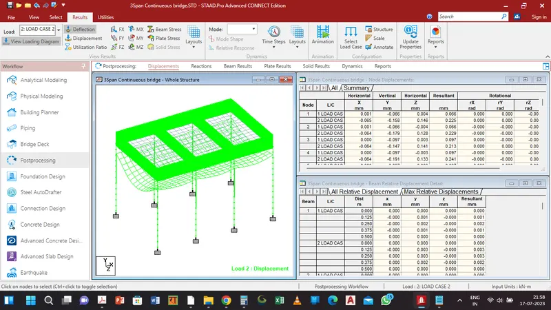
b) Three-Span Continuous Bridge:
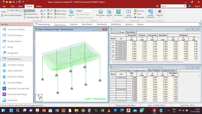
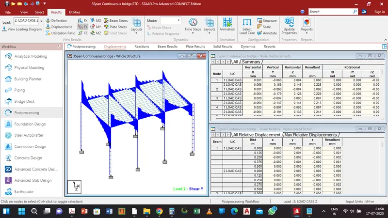
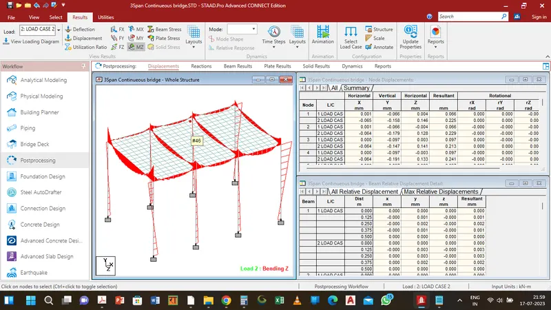
In a three-span continuous bridge, the additional effects on the bridge design would include:
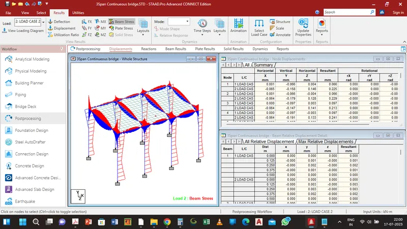
- Continuous girders: The girders would be designed to span multiple supports without expansion joints, allowing for smoother movement and reduced maintenance.
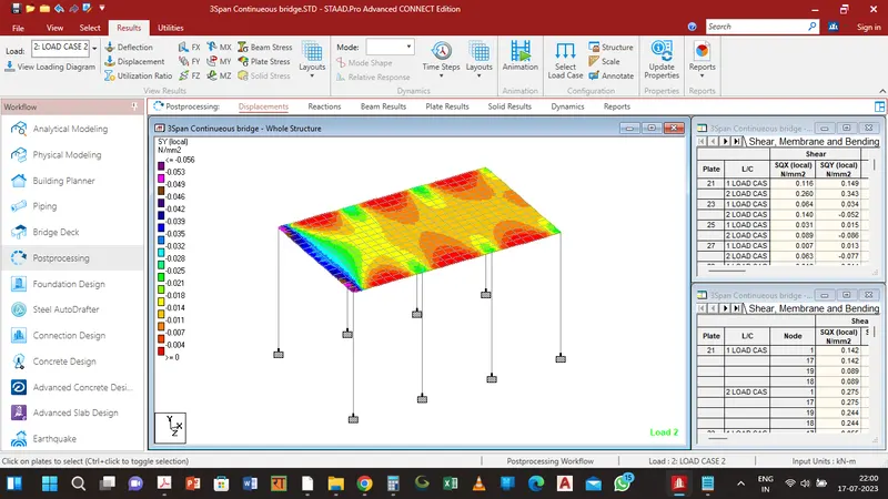
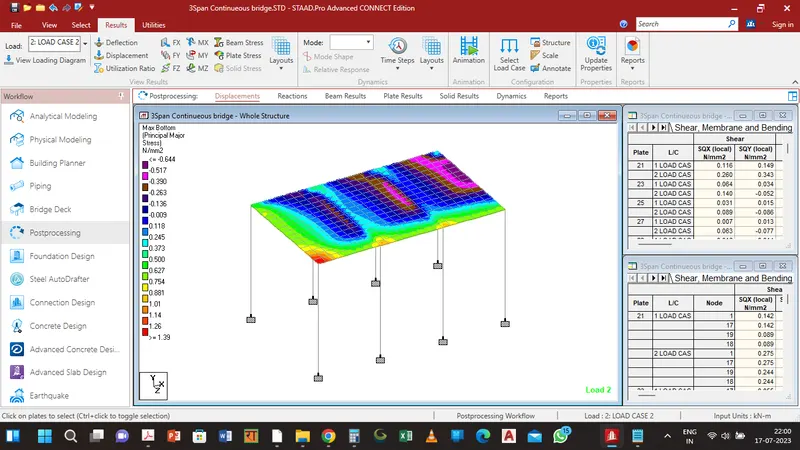
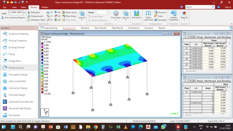
- Structural behaviour: The structural analysis would consider the behaviour of continuous girders, such as moments, shears, and deflections, and distribute the forces among the spans accordingly.
- Clause 203 - Dead Loads
- Clause 204 - Live Loads
- Clause 205 - Reduction in the longitudinal effect on bridges accommodating more than two traffic lanes
- Clause 206 - Foot over the bridge, footway, kerb, Railing, Parapet and Crash Barriers
- Clause 207 - Tramway Loading
- Clause 208 - Impact Loads
- Clause 209 - Wind Loads
- Clause 210 - Horizontal forces due to Water Currents
- Clause 211 - Longitudinal Forces
- Clause 212 - Centrifugal Forces
- Clause 213 - Buoyancy
- Clause 214 - Earth Pressure
- Clause 215 - Temperature
- Clause 216 - Secondary Effects
- Clause 217 - Erection Effects and Construction Loads
- Clause 218- Guidelines for Seismic Design of Road Bridges
- Clause 219 - Barge Impact on Bridges
- Clause 220 - Snow Loads
- Clause 221 - Vehicle Collision loads on the support of bridges, flyovers, supports and foot over bridges
- Clause 222 - Indeterminate Structure and Composite Structure
- Clause 201.2 - Hypothetical Vehicles for Classification of Vehicles
- Clause 202.3 - Combination of Loads for Limit State Design
- Clause 209.3.3 - Wind Load Computation on the truss bridge superstructure
- Clause 218.5 - Simplified Formula for Time Period
Shallow foundations, such as spread footings, are subjected to various forces that act on them. The specific forces acting on a shallow foundation can vary depending on the type of support structure, including free piers, fixed piers, and abutments. Here are the typical forces acting on shallow foundations in each case:
-
Free Pier:
- Vertical Load: The weight of the bridge superstructure and any live loads it carries. This load is transferred vertically to the foundation.
- Horizontal Load: Wind forces and lateral loads caused by the movement of vehicles on the bridge. These loads induce horizontal forces on the foundation.
- Moment: In some cases, there may be moments exerted on the foundation due to differential settlement or the bridge's structural behaviour.
2. Fixed Pier:
- Vertical Load: Similar to free piers, fixed piers also carry the vertical load from the bridge superstructure and any live loads.
- Horizontal Load: Fixed piers, being rigidly connected to the superstructure, resist horizontal loads more effectively. They can withstand lateral forces caused by wind, seismic activity, and vehicle movement.
- Moment: Fixed piers can also resist moments caused by differential settlement or the structural behaviour of the bridge.
3. Abutment:
- Vertical Load: Abutments support the vertical load of the bridge superstructure, including any live loads.
- Horizontal Load: Abutments experience horizontal loads due to soil pressure exerted by the backfill material behind them. These lateral forces are caused by soil movements and may vary with factors such as soil properties and water content.
- Moment: Abutments are subjected to moments resulting from the differential settlement between the bridge superstructure and the abutment.