Week 1 Challenge
1.1)answer:
- Open the STAAD pro software and locate the share option available on the introduction screen.
- After clicking on the share button, select send mail option.
- Then, browse for the. Std file on your machine & send it.
1.2)answer:
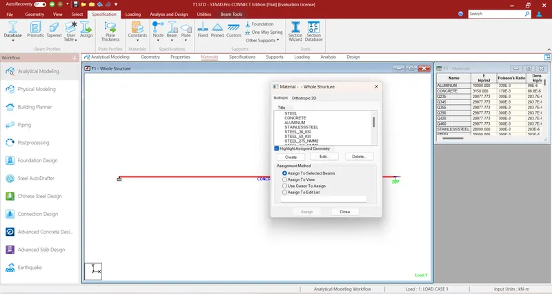
- STAAD.Pro includes a set of predefined materials for concrete, aluminum, steel, and stainless steel.
- Select the Materials page in the Analytical Modeling page control bar.
- In the Material - Whole Structure dialog Isotropic tab, click Create.
- Type a Title to identify the material.
1.3)answer: yes
1.4)answer:
- Using the STAAD.Pro Physical Modeler interface,
- using the traditional STAAD.Pro analytical modeling interface,
- and using the command file.
1.5)answer:
- Select the Material tool in the Assign properties group on the Member ribbon tab. The Assign material dialog opens. Select the Source for the material definition. Catalog - Used to select one of the included STAAD.Pro material definitions.
2.1)answer:
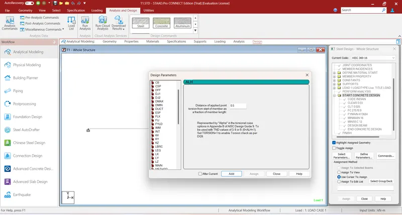
- Code.
- FU.
- FYLD.
- KY for strength check (Column)
- KZ for strength check (Column)
- LY for strength check (Beam)
- LZ for strength check (Beam)
- BEAM.
2.2)answer:
- Nodes Cursor,
- Beams Cursor,
- Plates Cursor,
- Solids Cursor.
2.3)answer:
- first we will prepare the geometry tab
- then specify the properties tab
- then assign the materials tab
- run design tab
- assign specifications tab and run analysis
2.4)answer:
- first we will start the program
- next generate the model geometry
- specify the member properties
- after that specify the support type i.e fixed or pinned
2.5)answer:
- Name of the project and the location of the project.
- Structural Layout.
- Introduction to the construction methodology.
- Quality Assurance and Quality Control.
- Budget of the Project.
2.6)answer:
- The term "Multi-material design" of STAAD Pro defines the structure that is designed by implementing more than one structural material.
3.1)answer:
Types of structures;
A STRUCTURE can be defined as an assemblage of elements. STAAD.Pro is capable of analyzing and designing structures consisting of frame, plate/shell, and solid elements. Almost any type of structure can be analyzed by STAAD.Pro.
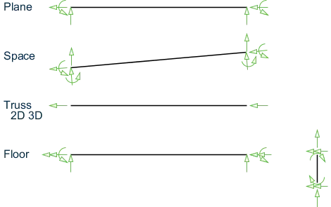
- SPACE
- A3D framed structure with loads applied in any plane. This structure type is the most general.
- PLANE
- This structure type is bound by a global X-Y coordinate system with loads in the same plane.
- TRUSS
- This structure type consists of truss members which can have only axial member forces and no bending in the members.
- FLOOR
- A 2D or 3D structure having no horizontal (global X or Z) movement of the structure [FX, FZ, and MY are restrained at every joint]. The floor framing (in global X-Z plane) of a building is an ideal example of a this type of structure. Columns can also be modeled with the floor in a FLOOR structure as long as the structure has no horizontal loading. If there is any horizontal load, it must be analyzed as a SPACE structure.
Specification of the correct structure type reduces the number of equations to be solved during the analysis. This results in a faster and more economic solution for the user. The degrees of freedom associated with frame elements of different types of structures is illustrated in the following figure.
- Global coordinates system;
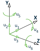
This coordinate system is a rectangular coordinate system (X, Y, Z) which follows the orthogonal "right hand" rule. This coordinate system may be used to define the joint locations and loading directions. The translational degrees of freedom are denoted by u1, u2, & u3 and the rotational degrees of freedom are denoted by u4, u5, & u6.
- Local coordinates system;
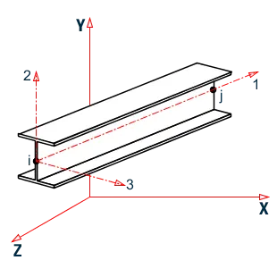
Each member or surface has its own local Cartesian coordinate system which is also oriented using the "right hand" rule.
The longitudinal axis of a member is the first axis, with the positive axis taken from the i to the j ends (i.e, Ni and Nj). The second axis is the oriented such that the 1-2 plane is then parallel to the global Y axis. The third axis is then normal to the first and second local axes as defined by the right hand rule. The local 2 and 3 axes coincide with the two principle moments of inertia of the cross-section. In the special case of a vertical member (where the local 1 axis is parallel to the global Y axis; i.e., a column), the local 3 axis is then made parallel to the global Z axis and the 2 axis is oriented respectively.
 |
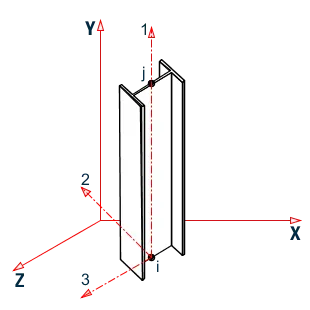 |
| (A) | (B) |
3.3)answer:
Design basis report;
- It is essentially a set of conditions, requirements, needs of the project & performance criteria, including the legal and code requirements.
3.4)answer:
- It can make use of various forms of analysis from the traditional static analysis to more recent analysis methods like p-delta analysis, geometric non-linear analysis, Pushover analysis (Static-Non Linear Analysis) or a buckling analysis.
3.5)answer:
- When the FIXED or FIXED BUT type of support is specified, for those degrees of freedom which are to be treated as fully restrained, STAAD assumes the displacements to be known quantities whose value is zero. Hence, those degrees of freedom are not considered for the stiffness matrix, and their value is not calculated. (For the FIXED BUT support type, if any degrees of freedom are assigned a spring using the KFX thru KMZ terms, those are treated as unknowns and their displacements are calculated).
PRACTICAL:
To create a STAAD PRO model following given procedure.
Procedure:
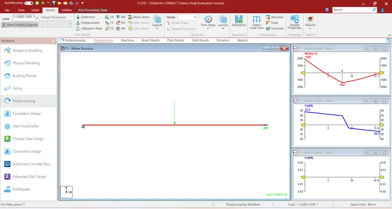
Result: SFD & BMD of given beam is shown.