Week 1 Challenge
AIM : Write the steps involved to upload a .std file through web mail?
Introduction :
- STAAD pro ( Structural Analysis and Deign program is the abbrivation for the STAAD it is the connected version new version used to analize the RCC structure and steel structure by using this software )
- It Include the GUI Graphic User Interface for Visualization and contains various design codes
Procedure :
- Open the software Staad pro in the landing page
- Click on share icon in
- Click on send mail
- Browse the file u want to share
- click on send mail
- Ensure that you are sign in
c) If you want to get the pictures in an external file ( like a word file, excel file, MsPaint etc.) go to the menu option Edit > Copy Picture, open the application you want and do a paste in there. Files saved through Take Picture option are not directly saved in common picture formats like bmp, jpg, png.
- press tab,the navigate arrow key to edit menu,then click on take picture
d) There are three methods of creating the structure data:
- Using the STAAD.Pro Physical Modeler interface,
- using the traditional STAAD.Pro analytical modeling interface,
- and using the command line
The physical model is used to draw structural elements as they are physically constructed. The program will then decompose this into an analytical modeling which is passed to the STAAD.Pro analysis and design engine when you run your model.
The analytical model is a finite element model of the structure which is typically processed directly by the analysis and design engine.
The command input file is a text file which contains the data for your structural model. This file consists of simple English language-like commands. This file is created for you behind the scenes for you when you model your structure using either the physical modeler interface or the analytical model interface.
e)
In STAAD.Pro Physical Modeler, the general order of operations is that you first select physical objects and then assign properties or perform some operation on the selection.
This differs from STAAD.Pro, where there are many tasks in which you select the operation, property, or specification first and then assign that to some list of model objects.
| Tool name | Description |
|---|---|
 Nodes Cursor |
Used to graphically select nodes. |
 Beam Cursor |
Used to graphically select beams. |
 Plate Cursor |
Used to graphically select plates. |
 Solid Cursor |
Used to graphically select solids. |
 Geometry Cursor |
Used to graphically select nodes, members and elements of the structure simultaneously.
To select nodes, members, or elements using the Geometry Cursor, simply click on the desired structural components. To select multiple nodes, members and elements, hold while selecting. We may also select the structural components graphically by creating a window on screen with the cursor around these components. |
 Members Cursor |
Used in Steel Design or Concrete Design to graphically select all those beams defined as a same member in the member set up of member design, simultaneously.
Members may be user defined or may be generated automatically using the Auto Form Member tool. To select all the beams defined as a same member using the Member Cursor, just click on one beam. The other beams having the same member name as the selected one will automatically be selected. To select multiple physical members, hold down while selecting. You may also select the physical members graphically by dragging a fence area around these physical members using the cursor. |
 Plates & Solids Cursor |
Used to graphically select both plate and solid elements. |
 (Select) Text |
Used to add comments and titles to pictures and result diagrams. The added text can be plotted, too.
The inserted text can be deleted, moved, and modified using the text cursor. Refer to the Insert Text on the Utilities ribbon for a detailed description on inserting text and modifying it using the text cursor. |
 Previous |
Selects the last objects selected if they have been deselected or if the selection set has changed. |
 Load |
To navigating the model view
The view window contains a unique control device called the Rotation Gizmo which allows you to select set view orientations or to orient the model in the view about the global axes.
- Click the Rotation Gizmo to display preset views. Click the Invert icon to display the reverse of these views.
- Click and drag on the Rotation Gizmo axes to rotate the view about that global axis.
- Click on the zoom controls to zoom in or out of parts of the model. Click-and-drag the middle mouse button (i.e., scroll wheel) to pan the view.
- Click on the Perspective control to display the perspective switch and slider.
To navigating the model view
The view window contains a unique control device called the Rotation Gizmo which allows you to select set view orientations or to orient the model in the view about the global axes.
- Click the Rotation Gizmo to display preset views. Click the Invert icon to display the reverse of these views.
- Click and drag on the Rotation Gizmo axes to rotate the view about that global axis.
- Click on the zoom controls to zoom in or out of parts of the model. Click-and-drag the middle mouse button (i.e., scroll wheel) to pan the view.
- Click on the Perspective control to display the perspective switch and slider.
4. Explain the procedure to define a “Simply Supported” condition in STAAD Pro
ANS : Go to the support command in the tool palet command
- Click on create support command
- There we can get option like fixed support , pin support , Fixed but
- Enforced but support
- Cable support
- Inclined support
5. Name any five topics that you will include while creating DBR.
- DBR Design basis report
- To take up a project from the scrach to the end this is need
- To specify the data and compile data recived and analysis and design of structural element
- It contains the assumption and specification to develop the project
- It will help to avoid the scope and the creep that can derail the projec schedule and lead to budget overness
- Contains the general Column drawing
- Contains the projec planning
3. 1. Name the structure systems in STAAD Pro? Explain each system?
ANS : They are four structural system in staad pro
| Structure System | Geometry | Loading | Deform | Joint |
| Space | 3D | 3D | 3D | ANY |
| Plane | 2D | 2D | 2D | ANY |
| Frame | 2D | PARPEN TO XZ | PERPEN TO XZ | ANY |
| Truss | 3D | 3D | 3D | Pinned |
2: Explain the coordinate system adopted in STAAD Pro software.
ANS : They are two coordinate syytem in Staad pro
- Global Axis : Gloabal Axis is fixed in the coordiate system
- Local axis : local axis is variable
- This is used for the orientation of the beam with the load varible
3: Elaborate DBR and its uses.
ANS :
- DBR Design basis report
- To take up a project from the scrach to the end this is need
- To specify the data and compile data recived and analysis and design of structural element
- It contains the assumption and specification to develop the project
- It will help to avoid the scope and the creep that can derail the projec schedule and lead to budget overness
- Contains the general Column drawing
- Contains the projec planning
5. Explain the difference between Fixed and Fixed But condition.
ANS :
IN fixed condition the node or the end condition are fixed are restrained with the FX , FY, FZ and the moment are also restrained
In Fixed But condition the node are Fx and MZ are released as it is horizontal rolled support
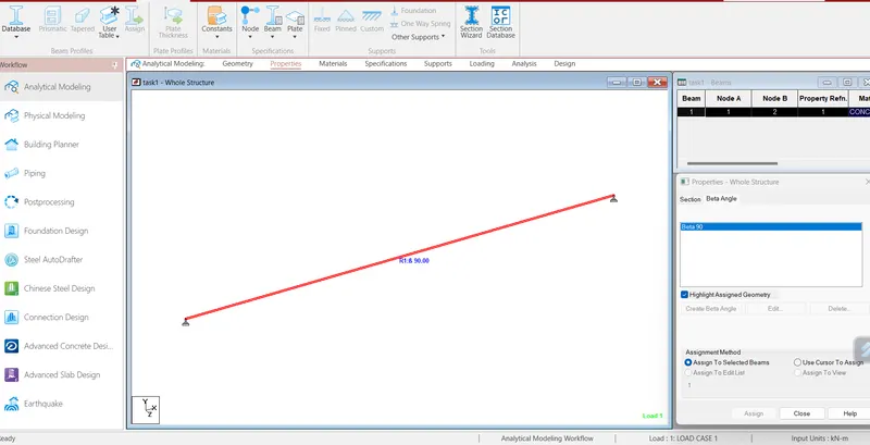
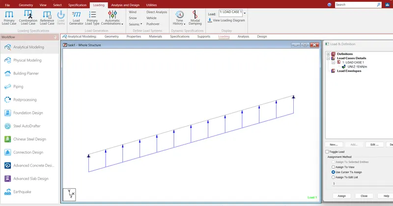
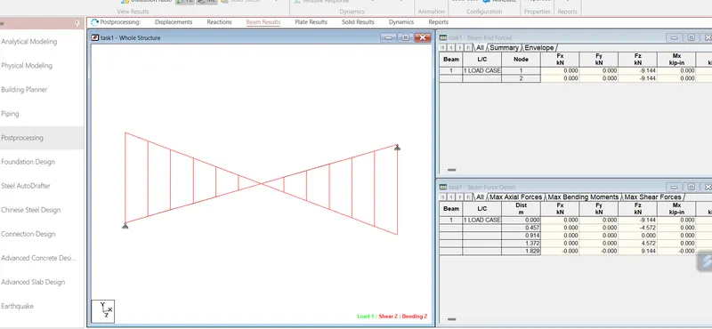
AIM : Creating a STAAD Model with the following Specification