Week 1 Challenge
1. 1. Write the steps involved to upload a .std file through web mail?
- Select back import from back stage, The import from STAAD.pro dailouge opens.
- Click general settings to browse and select a STAAD.pro(*.std) file to import.
- Select use mapping file in settings and then click to browse the select a mapping file to import.
- Set the catalog type and catalog isntance assignment fro the imported memeber types, the data used by AECO sim building to rebuild the members structural data as defined in the structural member catalog.
- In stells ection select a section definationthat is designated as default section name, this section defination is applied to imported memberswhose section data is not available in AECO sim building designer
- Check verify to scan the imported file for unknown selections.
- The unknown section dailouge box appears providing the oppurtunity to write unknown sections to the active XML section definition file before importing.
- In revision tracking check use design history track changes to a DGN file, viewing details about the revision using the controls on its tool.
- Check import, The update design dailouge appears, Review detailed information about each imported member and select which one to be imported before accepting them into target DGn file.
- Click update to compplete the iport process.
- The structure is updated.
2. Name the different materials that can be designed using STAAD Pro.
The materials that can be designed using STAAD.pro are
- Aluminium
- Concreet
- Steel
- stainless steel
3. Is it possible to capture images in STAAD Pro? If yes how?
Yes, We can take image in STAAD. pro using the command utilities. Plot the appropriate diagram and take a picture of it by " clicking the take picture icon".
4. Name the three ways by which you can create a model.
The three ways to create a model in STAAD.pro are
- Analytical model
- Physical model
- Building moddel
5. Write the steps followed to assign properties in a model.
In STAAD.pro physical model
- Open property in geomentry tab
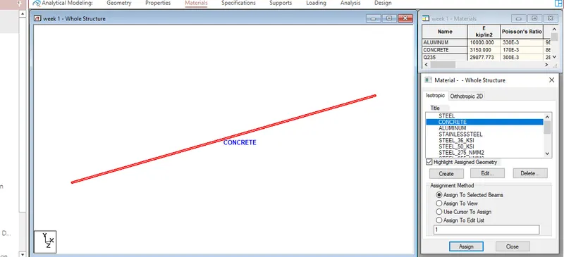
- Go to define material olption
- Select the members
- Select the material type
- Assign the property to the material
2. 1. Name any six design parameter involved in RCC design.
The six design parameters involved in RCC design are
- Clear cover
- FC, compressive strength of concrete
- FY, Tensile strength of steel
- Maximum main dia of bar
- Code of practice
- End concrete design
2. What are the different cursor types available in STAAD Pro?
The available cursor types are
- Node cursor
- Bema cursor
- Plate cursor
- Surface cursor
- Solid cursor
- Plate and solid cursor
- Geometric cursor
- Physical membrane
3. How will you generate different views for a model? State the steps involved.
Go to view option in the ribbon, there we have options like
- Top view
- Isometric view
- Front view
- Left view
- Right view
- Bottom view
- Back view
4. Explain the procedure to define a “Simply Supported” condition in STAAD Pro
- Go to the support command in the tool palet command
- Click on create support command
- There we can find different support commands like fixed, pin etc
- Select a command and apply to the required nodes.
5. Name any five topics that you will include while creating DBR.
Topics that will be included in DBR (Design basis report)
- Introduction of project
- Structural layout
- Load and load combinations
- Analysis and design methedology
- Quality assurance plan
- Assumption and specification to develop the project
- Project planning
- General column drawing
6. Describe the term “Multi material design” of STAAD Pro.
It is used for 3D model generation, analysis and multi-material design.
The STAAD.pro supports several steel, concrete and timber material in a separate member and this separate member will coordinate and form in to a structure.
3. 1. Name the structure systems in STAAD Pro? Explain each system?
A structure can be defined as an assemblage of elements. STAAD.pro is capable of analyzing and desigining structures consisting of frames, plate/shell and solid elements. Almost any type of structure can be analysed by STAAD.pro.
There are four structure systems in STAAD.pro
- Space : A 3D structure with loads applied in any plane. This structure type is most general.
- Plane : This structure type is bound by a global X-Y coordinate system with loadfs in the same plane.
- Truss : This structure type consists of truss members which can have only axial member forces and no bending in the emebers.
- Floor : A 2D or 3D structure having no horizontal (global X or Z) movement of the stucture [Fx, Fz and My arerestrained at every joint]. The floor framing of a building is an ideal example of this type of structure. Columns can also be modeled with the floor in a floori structure as long as the structure has no horizontalloading. If there is any horizontal load, it must be analysed as a space structure
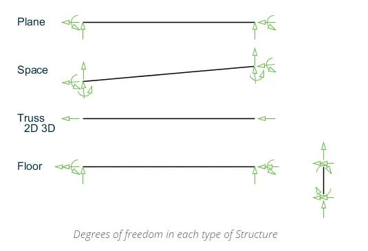
Specification of correct structure type reduces the number of equationsto be solved during analysis. This results in faster and more economicsolution fro the user. The degree of freedom associated with frame elements of different types of structure is illustrated in the following figure.
2. Explain the coordinate system adopted in STAAD Pro software.
STAAD.pro physical modeler uses conventional cartesian coordinate system, with the global Y axis assumed as vertical
- Global coordinate system : This is a frectangular coordinate system (X,Y,Z) which follows the orthogonal right hand rule. This coordinate system may be used to define the joint locations and loading directions
- Local coordinates : Each member or surface has its own local cartesian coordinate system which is also oriented using the right hand rule.
3. Elaborate DBR and its uses.
DBR elaborates to Design basis report
Uses :
- To take up project from start to end this is required
- To specify the data and compile data received and analysis and design of structural element
- It contains the assumtions and specifications to develop the project
- It will help to avoid the scope and creep that can derail the project schedule taht may lead to budget overload
- Contains general column drawing
4. Explain the different types of analysis options in STAAD pro.
Different types of analysis options
- Perfrom analysis
- P Delta analysis
- Push over analysis
- Non linear analysis
- Bulking analysis
5. Explain the difference between Fixed and Fixed But condition.
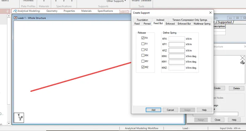
- In fixed condition the node or the end condition are fixed and are restrained with Fx, Fy and Fz and the moments are also retrained
- In fixed but condition the nodes Tx and Mz are released as it is horizontal roller support.
Practical
1. Create a STAAD Model with the following Specification
a. A beam of span 16m
b. Support : Fixed on one end and Roller support(Horizontal) on the other end
c. A point load of 50 kN at the mid-point
d. Draw SFD and BMD using software
Aim :
To create a STAAD Model with the following Specification
a. A beam of span 16m
b. Support : Fixed on one end and Roller support(Horizontal) on the other end
c. A point load of 50 kN at the mid-point
d. Draw SFD and BMD using software
Procedure :
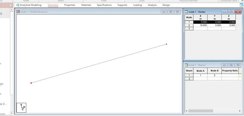
a. A beam of span 16m
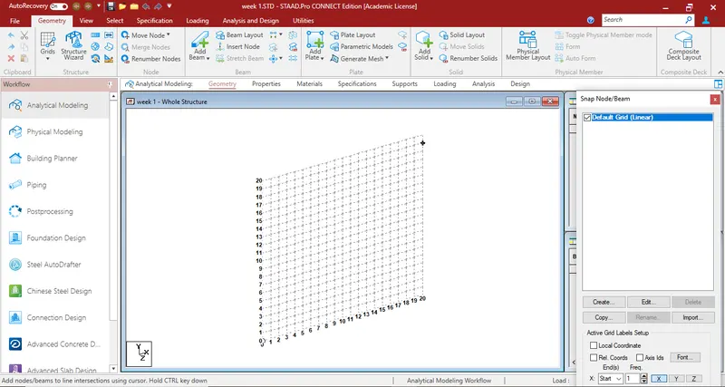
- Open STAAD.pro and create a new file as analytical type with metric units
- Go to beam tab and enter to take 16m beam
b. Support : Fixed on one end and Roller support(Horizontal) on the other end
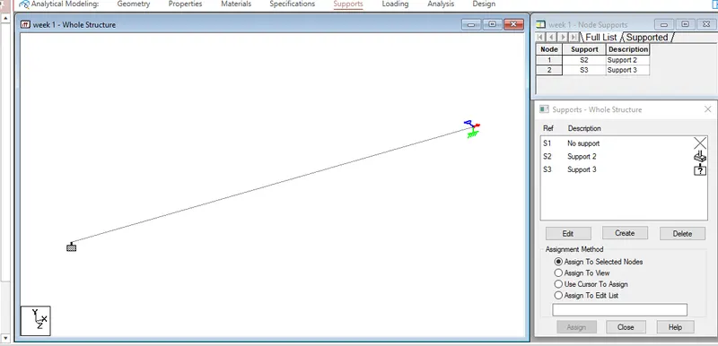
- Go to supports and take fixed and roller suppoers at each side of the beam
- Assign supports to the beam
c. A point load of 50 kN at the mid-point
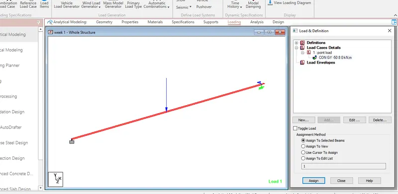
- To apply loads, go to loading option and enter load case details and click on edit and create loads
- Go to member load and take concentrated load and enter -50kn as the load value ( as 50kn load is acting down wards)
- Now, assign load to the beam
d. Draw SFD and BMD using software
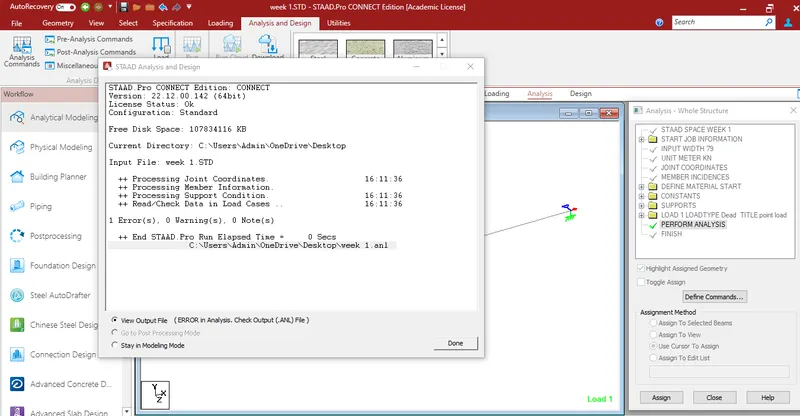
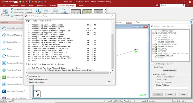
- Go to analysis option, click on perform analysis and run analysis
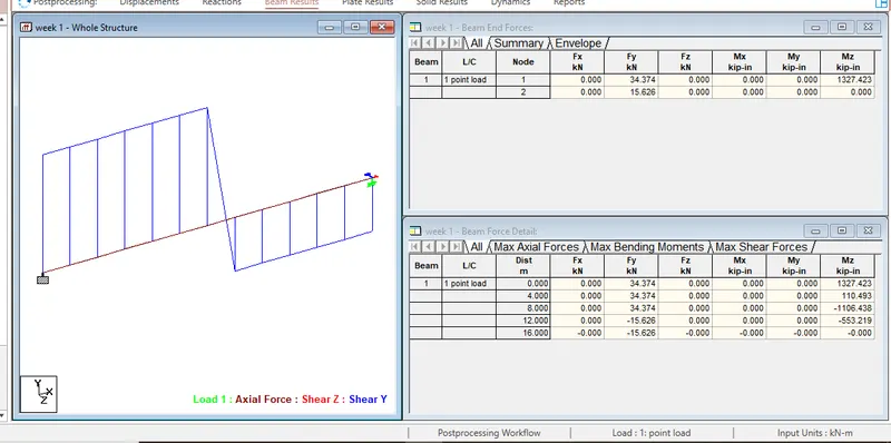
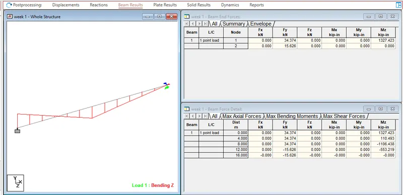
- The results are in the form of shear force and bending moment diagrams
Result :
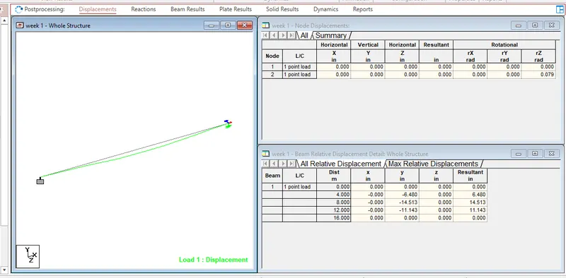
Displacement diagram, Shear force diagram and bending moment diagram are drawn using the software