Week 1 Challenge
Q1
1.
Following are the steps needed to upload an a.std file over webmails:
Locate the share option on the introduction screen by opening the STAAD pro program.
Select the option to send mail after clicking the share button.
Then find the standard file on your computer and email it.
2.
Different materials that can be designed using STAAD Pro. are as below;
- Concrete.
- Steel.
- Aluminium.
- Timber.
- Composite sections.
3.
YES
In STAAD Pro, it IS possible to take pictures.
Using the take photo command, which is available in the utility panel and has a camera logo,
we may take images of models and structural results in Staad Pro.
4.
The following are three methods for creating a model in STAAD pro:
- Analytical model.
- Physical model.
- Building planner model.
5.
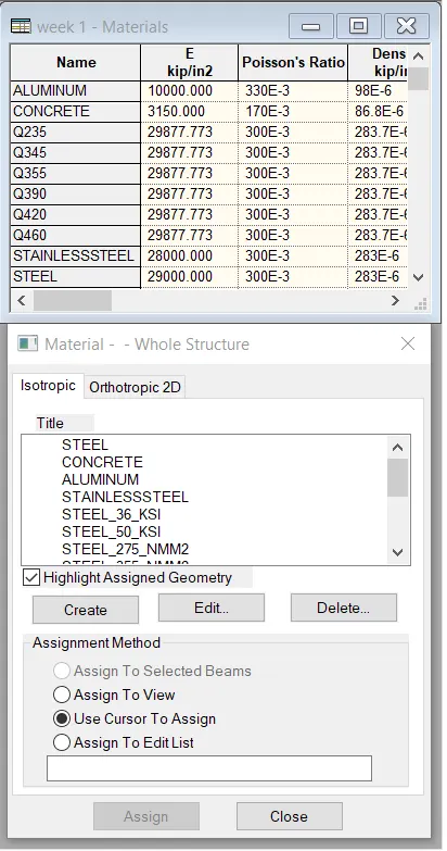
- Go over to the properties panel.
- Select Materials.
- Choose your preferred material from the selection, which includes stainless steel, concrete, steel, and aluminum.
- Then, verify the assignment method according to your preferences, such as assigning to view or utilizing the cursor.
- After selecting the radio option, give your model the material attribute.
Q2.
1.
The six Design parameters involved in RCC design are as below;
- Clear cover
- FC compressive strength of concrete
- FY Tensile Strength of steel
- Max main Dia of bar
- Code of practice
- End conrete design
2.
The different cursor types that are available in STAAD Pro are listed below:
- Nodes cursor.
- Plates cursor.
- Beams cursor.
- Plates and Solid cursor.
- Loads cursor.
- Solids cursor.
- Physical Member cursor.
- Geometry cursor.
3.
First, go to the view option in the ribbon there we can get options like as below;
- Top view
- Isometric view
- Front view
- Left view
- Right View
- Bottom view
- Back view
4.
PROCEDURE:-
Go to the support command in the tool pallet command
- Click on create support command
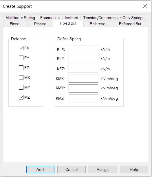
- There we can get options like fixed support, pin support, Fixed but
- Enforced but support
- Cable support
- Inclined support
5.
Let's first define DBR, shall we? DBR stands for Design Brief Report.
- Therefore, DBR is essentially a succinct summary of what, why, and where you want to produce.
- It is, in essence, a crucial component of our project. Following is a list of the five themes that will be included in creating DBR:
- Name of the project and the location of the project.
- Structural Layout.
- Introduction to the construction methodology.
- Quality Assurance and Quality Control.
- Budget of the Project.
6.
- It is used for 3D model generation, analysis, and multi-material design.
- The STAAD.Pro supports several steels, concrete, and timber material in a separate member
- This separate member will coordinate and then formed into a structure
Q3.
1.
The structure systems in STAAD Pro software are:
- Space Frames.
- Plane Frames.
- Trusses.
EXPLANATION: SPACE FRAMES:-
Therefore, space frames can be thought of as three-dimensional truss-like constructions that are intended to carry loads over long distances without the need for intermediate supports. The space frame constructions are strong structurally and lightweight and stiff in character. It is inexpensive to transport.
PLANE FRAMES:-
RCC or steel frames are used in plane design. It is a two-dimensional construction made of straight pieces that are joined together by hinged or stiff connections.
TRUSSES:-
Trusses are created by arranging the structural elements in triangle forms which can take loads in both compression and tension.
2.
The coordinates system that is adopted in STAAD Pro software is X, Y, and Z coordinates.
So basically the co-ordinate system adopted in STAAD Pro software is:
- Global Axis:- Mainly global axis is fixed in the coordinate system.
- Local Axis:- Local axis is variable in nature. We can change the local axis but not the global axis.
- Similar to the STAAD Pro software. It essentially employs a standard cartesian coordinate system, where Y is a global axis that runs upward. We can assert that the structure's height is consistently parallel to the world Y-axis.
3.
The DBR (Design Brief Report) is essentially a project management document that contains various details on the building of the structure. This DBR is a thorough report that goes into great depth on the current building project. In outlining the Client's requirements for the building job, it specifies the last step in the process. This report basically contains all of the significant structural information that is relevant to, or we might say that is related to, the project, such as a client description, site information, special requirements if any, technical requirements, components needed, project requirements, and other construction-related issues.
4.
The different types of analysis options in STAAD Pro software are listed below:
- Linear Elastic analysis.
- P-Delta analysis.
- Buckling analysis.
- Pushover analysis.
5.
Fixed condition:
In the STAAD Pro software, a fixed condition is one in which all of the degrees of freedom—horizontal, vertical, or moment—are fixed, or, to put it another way, these conditions are constrained and cannot be changed. We can say that those circumstances are fixed circumstances.
Fixed-But condition:
Regarding the fixed-end condition, we may remark that its end conditions can be adjusted as necessary. The final condition is not constrained in this situation, thus we can adjust it. Some of the necessary degrees of freedom can be released.
PRACTICAL:
PROCEDURE:-
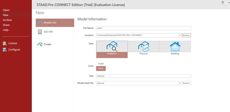
- Open the STAAD pro Software and Create a New Model
- The first step is to initiate the project in staad.pro
- The same can be done by clicking on the new option available on the staad intro screen.
- After clicking on the new model, you can feed the project details.
- Also, you will be asked to specify a location within your system.
- Then, click on create to start a new project.
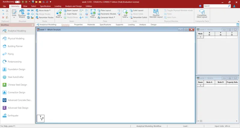
- Now draw the Beam of the Required Span
- To model the proposed beam, go to geometry and create the first node at X-0, Y-0, and Z-0.
- Then, select the created node by switching to the node cursor.
- Press ctrl+c and ctrl+v.
- Specify the span length that is 16 meters in the X-direction and hit enter.
- Both the ends of the required beams are created now go to add beam>select first node and then second to create a beam of the proposed length.
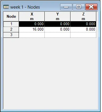
Nodes

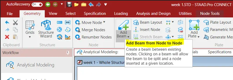
Beam
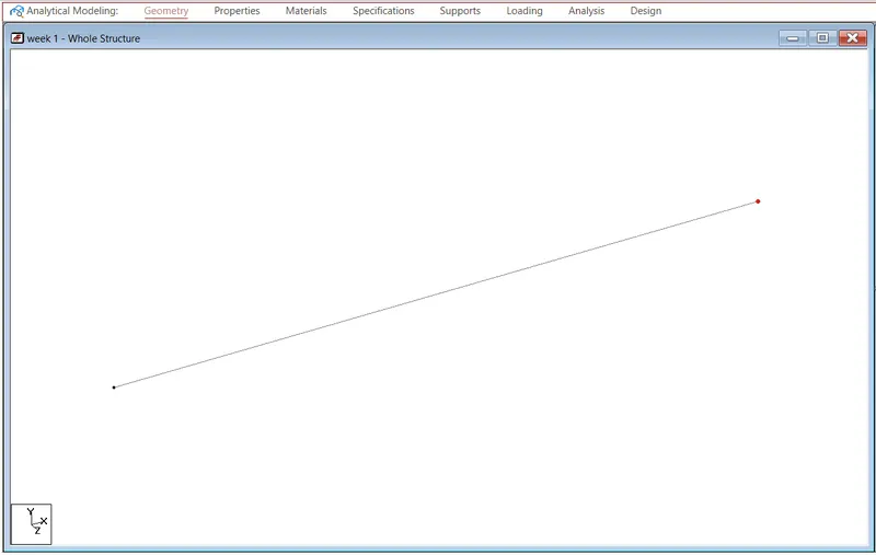
- Assign Support Conditions
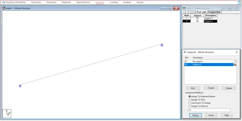
- Go to support>add>fixed>select one node>assign to selected nodes>enter.
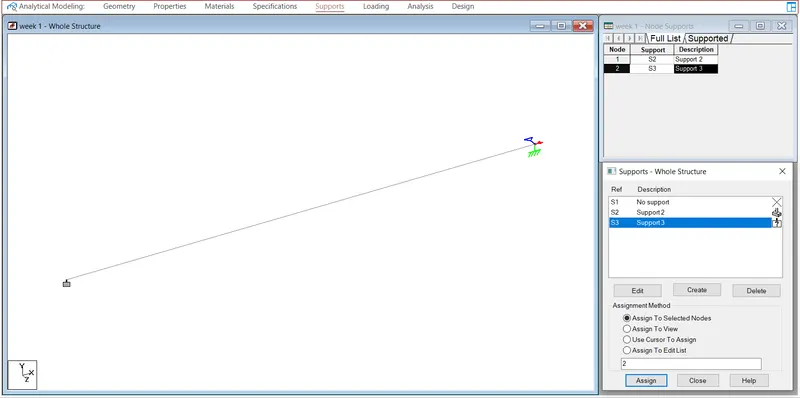
- Similarly, create another node>fixed but>release moments and horizontal restraints>ok>select the other node>assign to selected>ok.
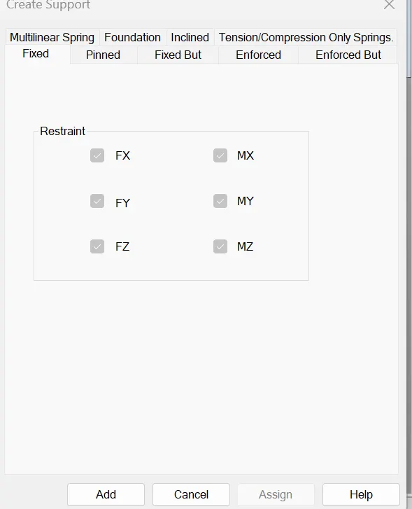
- give properties to the beam with and thickness
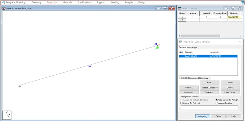
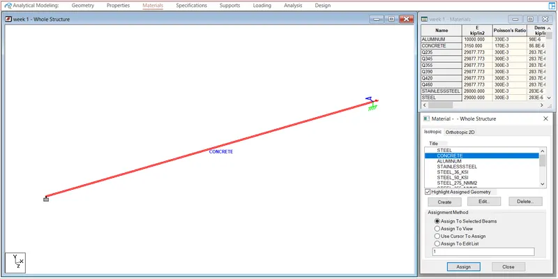
- give materials to the beam as a concrete
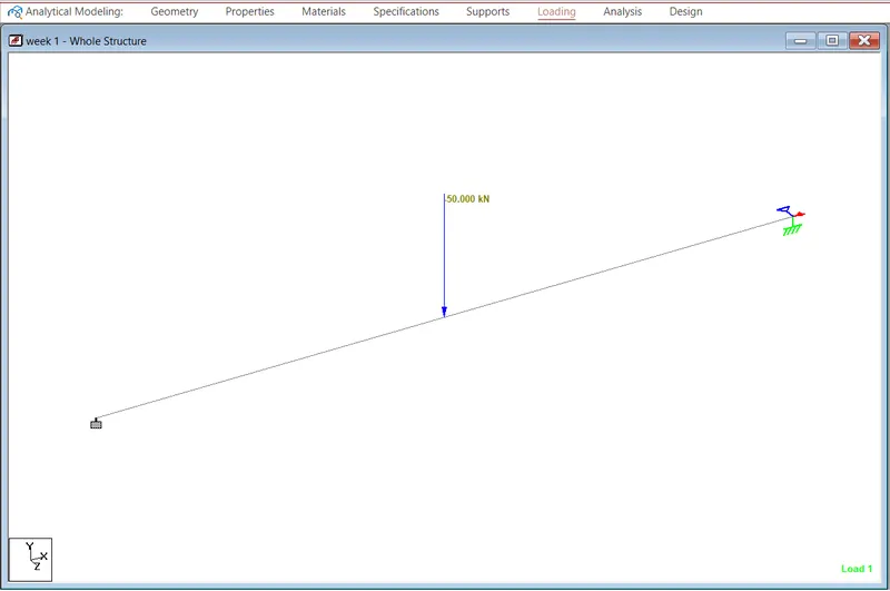
- Assign the Proposed Load
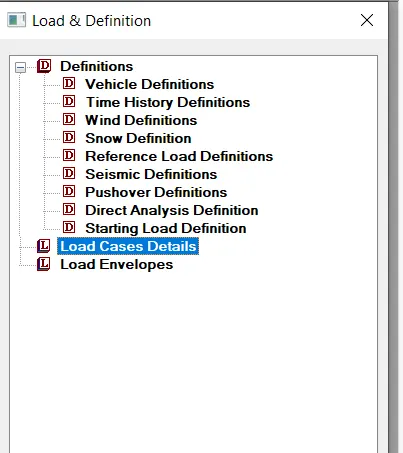
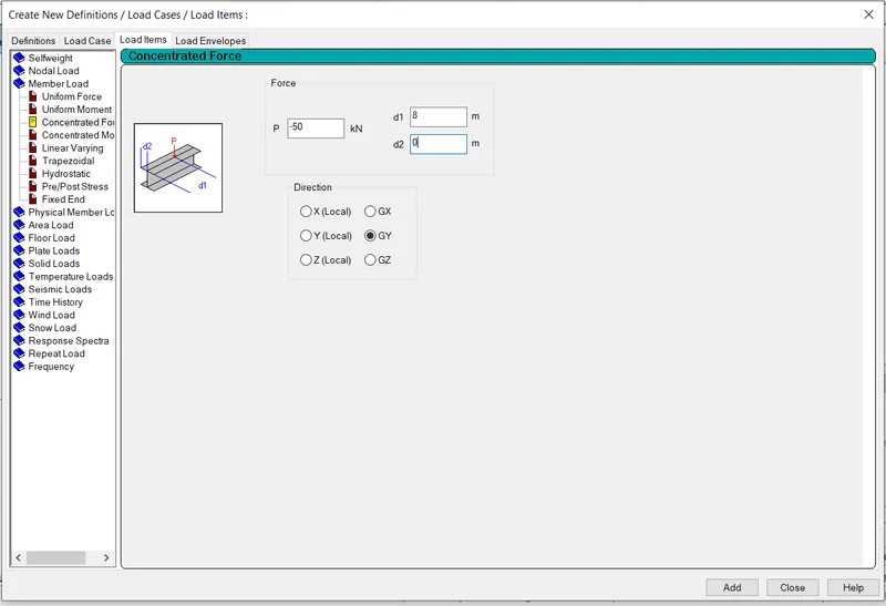
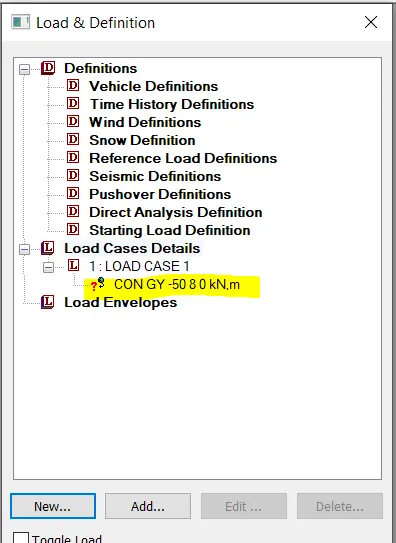
- Go to loads>create>member load>globa Y>-50KN>d1-5, d2-5>OK.
- Now, select the load and beam and check the radio button for assign to selected>apply>ok.
- Run the Analysis
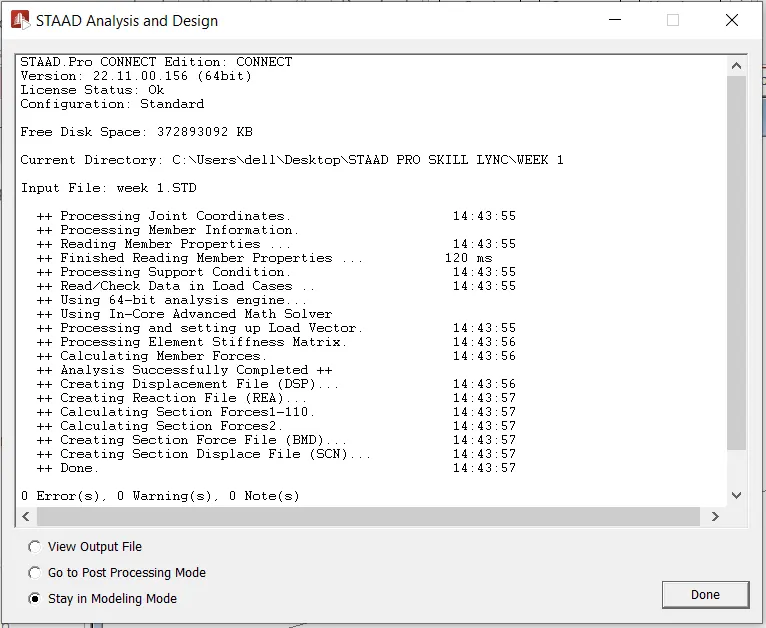
- After this, select the analysis method that is perform analysis from the design and analysis panel.
- Once you are done with setting up the analysis method, go ahead and run the analysis from the analysis and design panel.
- Wait some time for the analysis to get complete and look for errors and warnings.
- If there are no errors or warning signs upon completion of the analysis, you're good to go.
- Draw SFD and BMD
- Now, go to the post-processing mode>select the load cases>click apply>ok.
- Then, all the analysis results will be automatically visible on your staad screen.
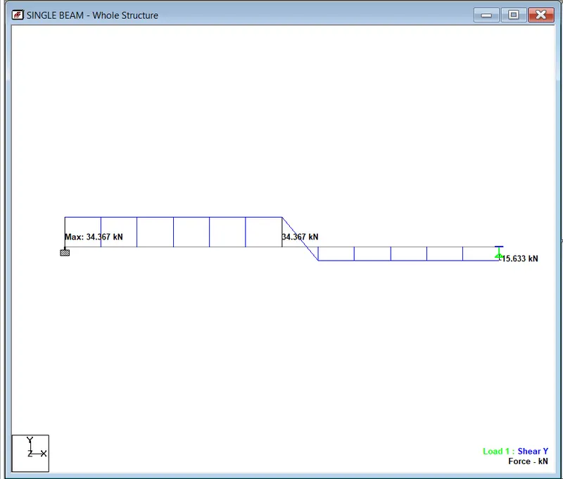
- Select beam results>Mz for bending moment>Fy for shear force diagram.
- Make sure to check the annotate option to view the values along with the diagrams as inserted below:
Shear Force Diagram
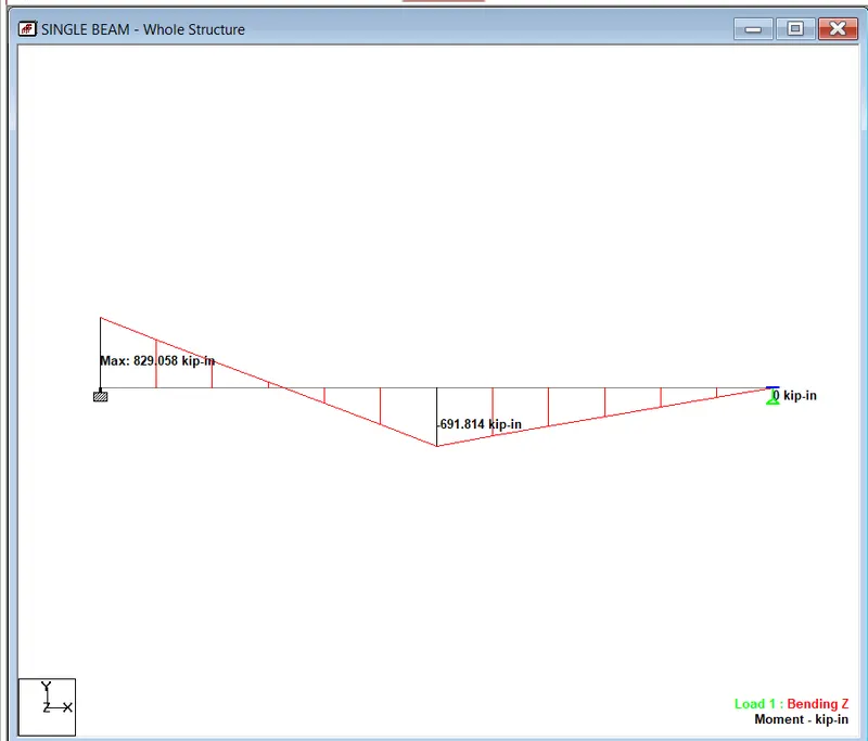
Bending Moment Diagram