Week 1 Challenge
Foundation is the component of bridge which accepts the external or internal forces / loads coming through substructure and superstructure and spreads the forces /loads uniformly to the earth. It also guarantees stability of whole structure as well as self protection from scour.
So bridge designer’s prime aim is to design and construct an economical and stable foundation for 100 and more than 100 years.
Mainly there are two types of foundation, based on relation of depth and breadth.
Type – 1 Shallow foundation whose depth is equal or lesser than breadth.
Shallow foundations are of 5 types based on footings
A. Combined footing,
B. Mat footing,
C. Spread and isolated footing,
D. Strip footing,
And E. Strap or cantilever footing.
Type – 2 Deep foundations whose depth is greater than breadth.
Deep foundations are of mainly two types: Pile foundation and well foundation.
Selection of combined footing, (shallow) combined footing foundations are selected based on
criteria No -1 available top soil has sufficient bearing capacity,
and No – 2 the area of ground required, considering the loads of structure and bearing capacity of soil can accommodate two or more columns.
Selection of mat footing, Mat footing (shallow) foundations are selected based on criteria No -1 available top soil has sufficient bearing capacity,
and No – 2 the area of ground required, considering the loads of structure and bearing capacity of soil can accommodate total columns of the structure.
Selection of spread and isolated footing, Spread and isolated (shallow) footing foundations are selected based on criteria No -1 available top soil has sufficient bearing capacity,
and No – 2 the area of ground required, considering the loads of structure and bearing capacity of soil can accommodate single column of the structure.
Selection of srip footing, Strip (shallow) footing foundations are selected based on criteria No -1 available top soil has sufficient bearing capacity,
and No – 2 Two or more column of the structure required to rests on one footing, for example wider deck of superstructure demands two or more pillars in one base. Using single column may transmit load as cantilever, so strip footing is in trend.
Selection of strap or cantilever footing, Strap or cantilever (shallow) footing foundations are selected based on criteria No -1 available top soil has sufficient bearing capacity,
and No – 2 Where there is constraint of area of ground required, considering the loads of structure and bearing capacity of soil.
Selection of Pile foundation (deep) Pile as deep foundation are selected based on criteria No - 1 available top soil has poor bearing capacity.
Criteria No - 2 liquification of soil,
Criteria No -3 Presence of canal or deep drainae lines near the foundation
Criteria No - 4 Structure near sea shore or river bed
and criteria No -5 Sub soil has scouring tendency and the water current add to its effect.
Selection of well foundation (deep) Well as deep foundation are selected based on criteria No - 1 available top soil has poor bearing capacity and zero cohession.
Criteria No - 2 liquification of soil,
Criteria No -3 Presence of canal or deep drainae lines near the foundation
Criteria No - 4 Structure near sea shore or river bed
Criteria No - 5 Large fluctuations in subsoil water level
and criteria No - 6 Scouring is anticipated
Q. 2.Name all the components of a RCC girder bridge resting on open foundation. what additional effects it will create if we have a) seismic case 5,
A -
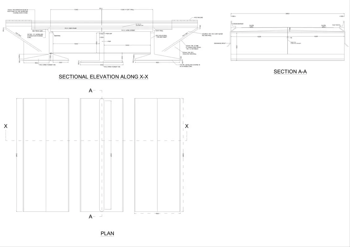
Q 2.Name all the components of a RCC girder bridge resting on open foundation. what additional effects it will create if we have a) seismic case 5
218.2 code IRC 6) For Seismic Zone V factor is 0.36
218.5.5 Code IRC 6) Response reduction factor for this bridge will be 5 ( RC building with special moment resisting frame)
218.5.1.1 Code IRC 6) Importance factor for this bridge will be 1.5 (Important building)
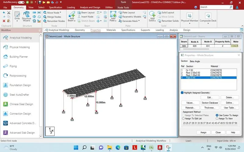
Bridge modelled for span 12m and carriageway 7.5m
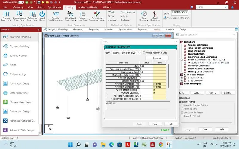
Seismic defination for zone 5
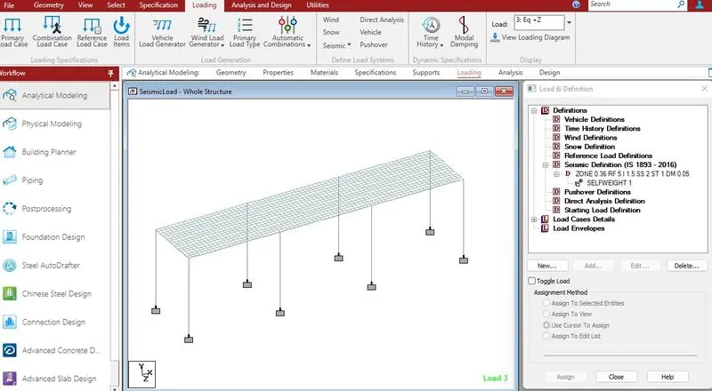
Self weight added.
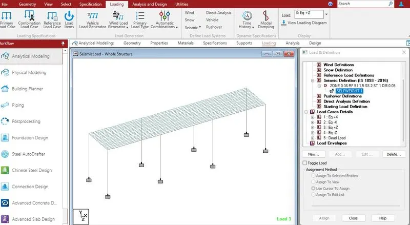
5 load case detail added.
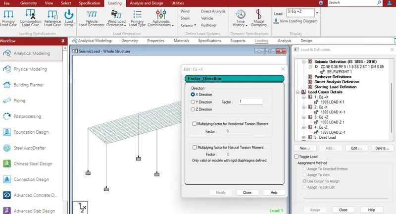 Generated load assigned to load case detail.
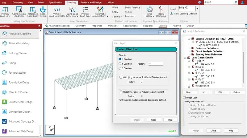 Reverse of X direction.
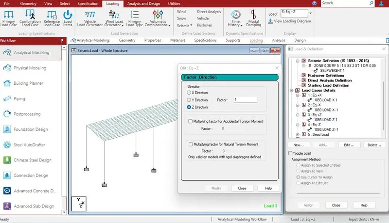 Z direction.
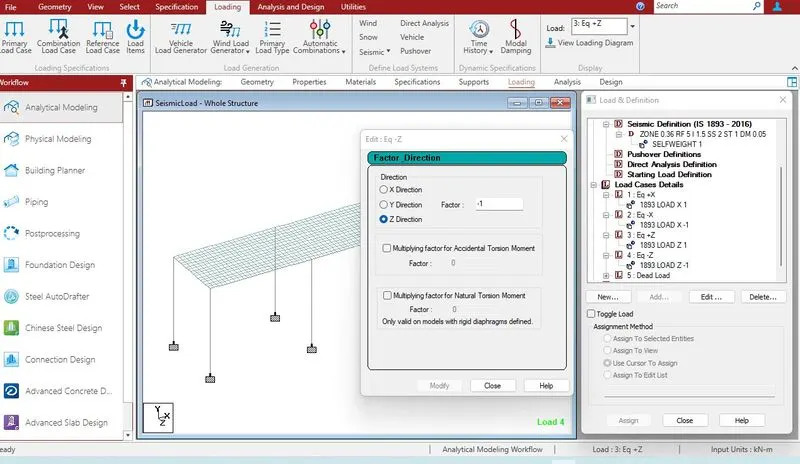 Reverse Z direction.
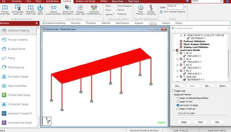 Self weight assigned.
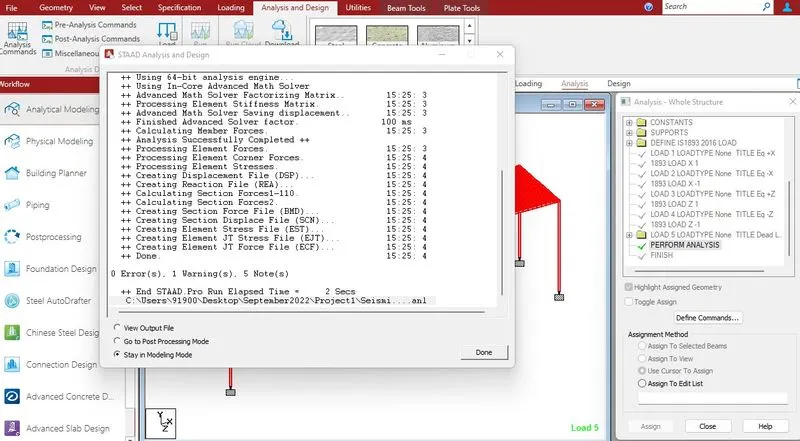 Design and analysis performed successfully.
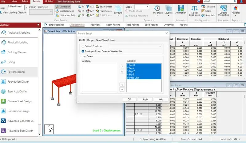
All the loads selected.
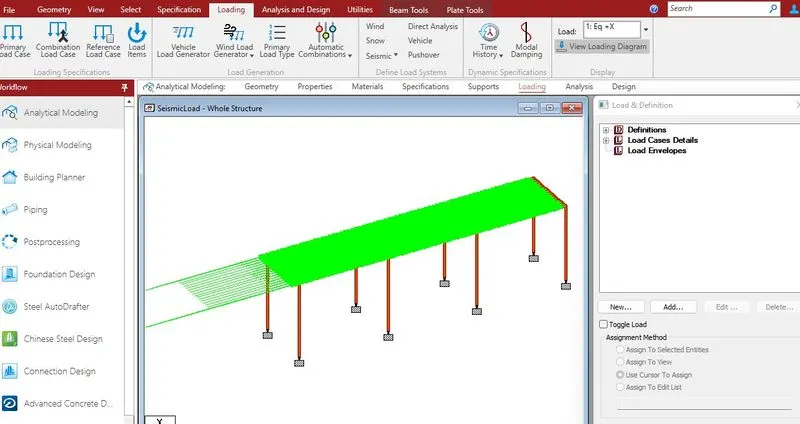
Load diagram in + X direction.
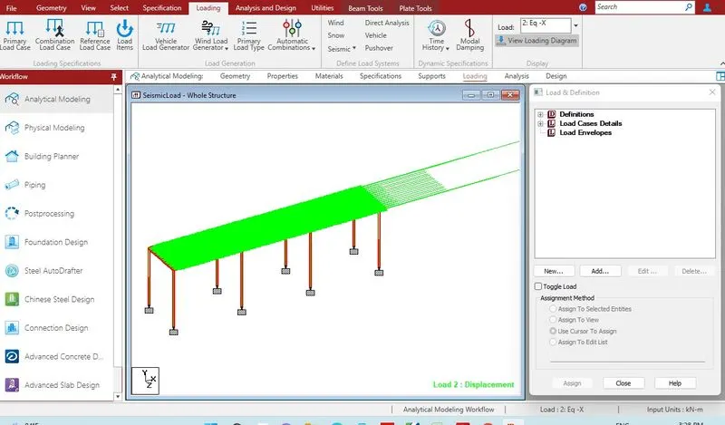
Load diagram in - X direction.
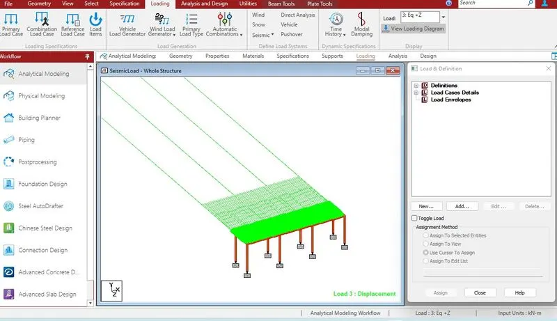
Load diagram in Z direction.
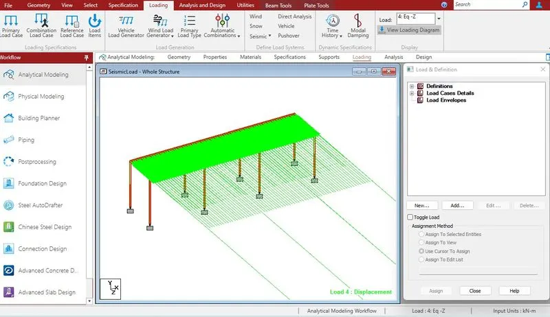 Load diagram in - Z direction.
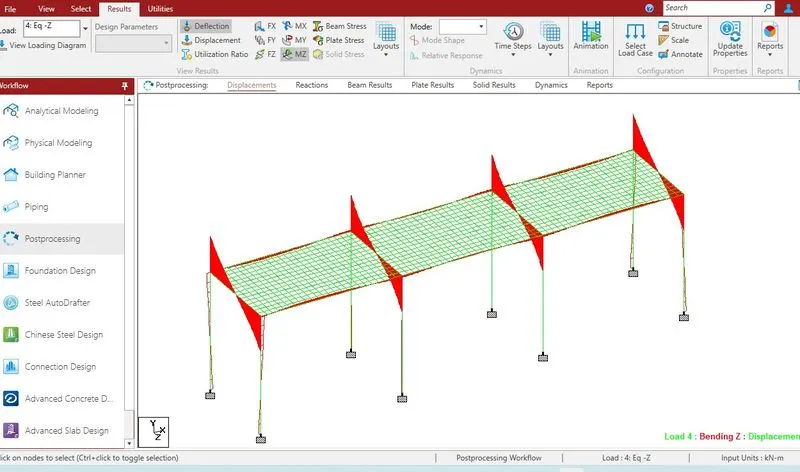
Bending moment for seismic load in - Z direction.
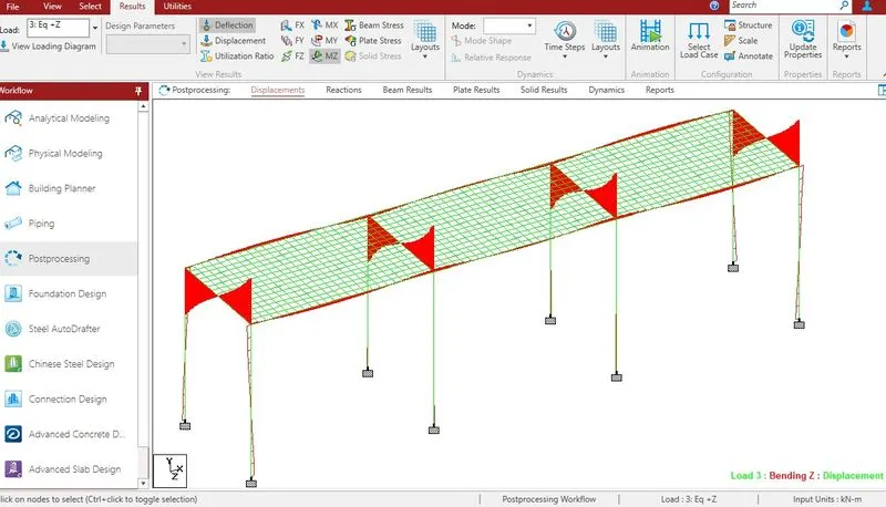
Bending moment for + Z direction.
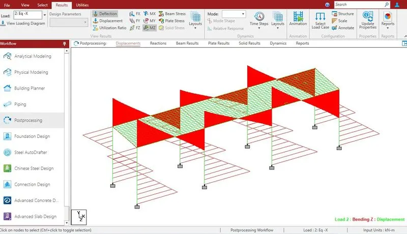
Bending moment for seismic load in - X direction.
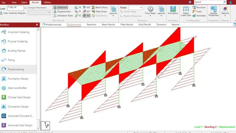
Bending moment for seismic load in + X direction.
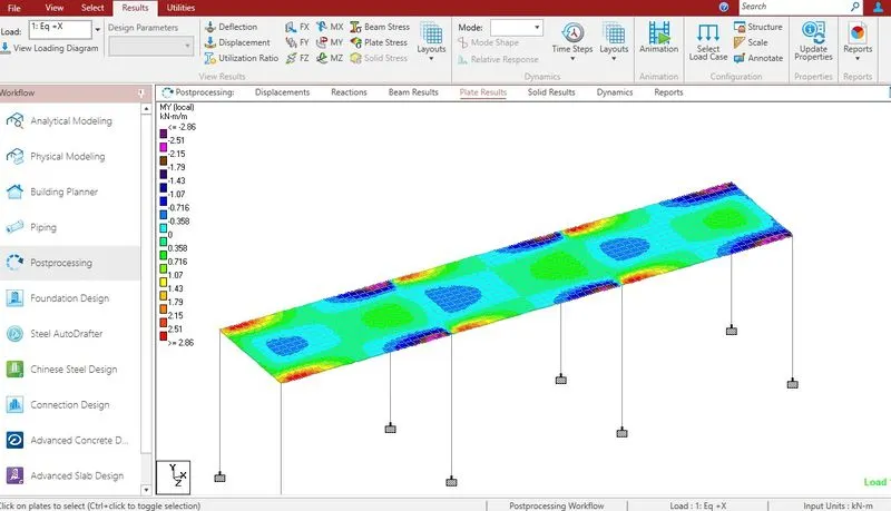
Plate stress due to seismic load in X direction.
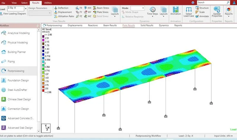
Plate stress due to seismic load in - X direction.
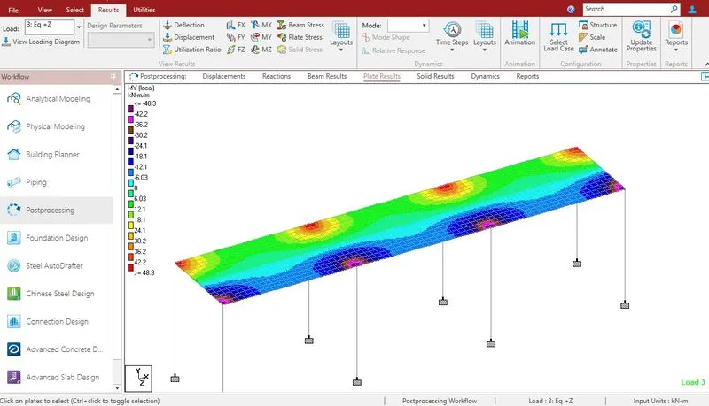
Plate stress due to seismic load in Z direction.
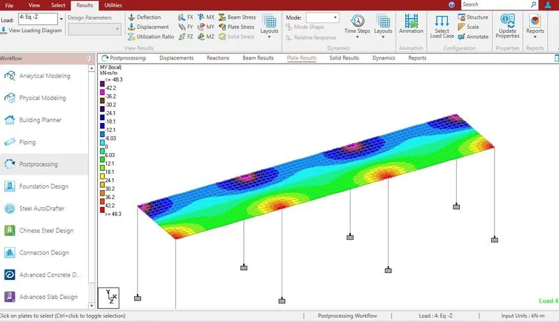
Plate stress due to seismic load in - Z direction
b)3 span continuous bridge Position all the loads on the bridge having 12 m and 7.5 m carriageway transverse width with to the scale drawings.
1. Dead load
The self weight of structural elements are calculated based on the following concepts
To calculate as a per meter loading (UDL) Self weight (kN/m) = Unit weight X cross sectional area of the structural element
To calculate as a point loading (Concentrated Load) Self weight (kN) = Unit weight X Volume of the structural element
2. Live load (Moving vehicle)
Code 204.1.2 IRC 6) Within the kerb to kerb width of the roadway, the standard vehicle or train
shall be assumed to travel parallel to the length of the bridge and to occupy any position
which will produce maximum stresses provided that the minimum clearances between
a vehicle and the roadway face of kerb and between two passing or crossing vehicles.
Code 204.1.3 IRC 6) For each standard vehicle or train, all the axles of a unit of vehicles shall be
considered as acting simultaneously in a position causing maximum stresses.
Code 204.1.4 IRC 6) Vehicles in adjacent lanes shall be taken as headed in the direction producing
maximum stresses.
204.1.5 Code IRC 6) The spaces on the carriageway left uncovered by the standard train of
vehicles shall not be assumed as subject to any additional live load unless otherwise.
204.3 Code IRC 6) Combination of Live Load for carriageway 7.5m One lane of Class 70R OR two lanes for Class A
Combination of Live Load for carriageway 12.5m One lane of Class 70R for every two
lanes with one lanes of Class A on the remaining lane OR 3 lanes of Class
Fatigue load (Cl 204.6 IRC - 6 2017)
Bridge near ports, heavy industries and mines and other areas where generally heavy vehicles ply, shall be designed for the stress induced due to 10 X 10to the power 6 cycles.
Other bridges shall be designed for the stress induced due to 2 X 10to the power 6 cycles.
Fatigue truck description
Width Tyre centre to centre 1.68m
Wheel arrange ment 1st 12t, 4.5m 2nd 14t, 1.4m 3rd 14t
Cl 205 IRC 6 REDUCTION IN THE LONGITUDINAL EFFECT ON BRIDGES
ACCOMMODATING MORE THAN TWO TRAFFIC LANES
For two lanes - No reduction
For three lanes - 10% reduction
For four lanes - 20% reduction
Four five or more lanes - 20% reduction
Cl 206.1 IRC 6) For all parts of bridge floors accessible only to pedestrians and animals and for
all footways the loading shall be 400 kg/m2. For the design of foot over bridges the loading
shall be taken as 500 kg/m2. Where crowd loads are likely to occur, such as, on bridges
located near towns, which are either centres of pilgrimage or where large congregational
fairs are held seasonally, the intensity of footway loading shall be increased from 400kg/m2 to 500 kg/m2. When crowd load is considered, the bridge should also be designed
for the case of entire carriageway being occupied by crowd load.
cL 206.2 irc 6) Kerbs, 0.6 m or more in width, shall be designed for the above loads and for a
local lateral force of 750 kg per metre, applied horizontally at top of the kerb. If kerb width
is less than 0.6 m, no live load shall be applied in addition to the lateral load specified
above.
Cl 206.3 IRC 6) In bridges designed for any of the loadings described in Clause 204.1, the main
girders, trusses, arches, or other members supporting the footways shall be designed for
the following live loads per square metre for footway area, the loaded length of footway
taken in each case being, such as, to produce the worst effects on the member under
consideration:
a) For effective span of 7.5 m or less, 400 kg/m2 or 500 kg/m2 as the case may be,
based on Sub-Clause 206.1.
b) For effective spans of over 7.5 m but not exceeding 30 m, the intensity of load
Cl 206.4 IRC 6) Each part of the footway shall be capable of resisting an accidental load of 4
tonne, which shall be deemed to include impact, distributed over a contact area of 300
mm in diameter. For limit state design
Cl 206.5 IRC 6) The Pedestrian/Bicycle Railings/Parapets
Design loads are of two basic type:
Type - 1 Solid / partially filled in parapet continuously cantilevering along full length from deck level.
Loading: Horizontal and verticle load of 150kg/m acting simultaneously on top level of the parapet
Type - 2 frame type with discrete verticle posts cantilevering from the curb / deck with minimum two rows of horizontal rails (third row bring the curb itself, or curb replaced by a low level third rail), the rails may be simply supported or continuous over the posts.
Each horizontal railing designed for Horizontal and Verticle load of simultaneously over the rail The fillar portion supported between any two Horizontal rails and verticle rails should be designed to resist horizontal load of 150kg/m2 The posts to resist horizontal load of 150kg/m X spacing between posts in m on top of the posts
Cl 206.6 IRC 6) Crash Barriers
Crash barriers are designed to withstand the impact of vehicles of certain weights at
certain angle while travelling at the specified, speed as given in Table 9. They are
expected to guide the vehicle back on the road while keeping the level of damage to
vehicle as well as to the barriers within acceptable limits
The crash barriers can be of rigid type, using cast-in-situ/precast reinforced concrete
panels, or of flexible type, constructed using metallic cold-rolled and/or hot-rolled sections.
The metallic type, called semi-rigid type, suffers large dynamic deflection of the order
of 0.9 to 1.2 m due to impact, whereas the ‘rigid’ concrete type suffers comparatively
negligible deflection. The efficacy of the two types of barriers is established on the basis
of full-size tests carried out by the laboratories specializing in such testing. A certificate
from such laboratory can be the only basis of acceptance of the semi-rigid type, in which
case all the design details and construction details tested by the laboratory are to be
followed without modifications and without changing relative strengths and positions of
any of the connections and elements.
P -1 : Normal containment Bridges carrying expressway or equivalent 15kN vehicle at 110km / hour and 20 deg angle of impact
P -2 : Low containment All other bridges except bridge over railway 15kN vehicle at 80km / hour and 20deg angle of impact
P -3 : High containment All hazardous andhigh risk locations, 300kN vehicle at 20km / hour and 20deg angle of impact
over busy railway lines, complex
interchanges etc.
Cl 208 IRC 6 IMPACT
Impact factor fraction for RCC Bridges 4.5/6+L Where L is span of the bridge.
209 WIND LOAD
| Wind Zones of India | ||||||||
| Under | 30 | m/s low damage risk jone | ||||||
| 33 | to | 39 | m/s low moderate damage risk jone B | |||||
| 39 | to | 44 | m/s low moderate damage risk jone A | |||||
| 44 | to | 47 | m/s high damage risk jone | |||||
| 47 | to | 50 | m/s very high damage risk jone B | |||||
| over | 50 | m/s very high damage risk jone A | ||||||
Cl. 210.1 IRC 6 Any part of a road bridge which may be submerged in running water shall be
designed to sustain safely the horizontal pressure due to the force of the curren
210.2 On piers parallel to the direction of the water current, the intensity of pressure
shall be calculated from the following equation:
P = 52KV square
Cl 213.1 IRC 6 In the design of abutments, especially those of submersible bridges, the effects
of buoyancy shall also be considered assuming that the fill behind the abutments has
been removed by scour.
Cl 213.2 IRC 6 To allow for full buoyancy, a reduction shall be made in the gross weight of the
member affected by reducing its density by the density of the displaced water.
Cl 215.1 IRC 6 Tempreture load General
Daily and seasonal fluctuations in shade air temperature, solar radiation, etc. cause the
following:
a) Changes in the overall temperature of the bridge, referred to as the effective
bridge temperature. Over a prescribed period there will be a minimum and a
maximum, together with a range of effective bridge temperature, resulting in
loads and/or load effects within the bridge due to:
i) Restraint offered to the associated expansion/contraction by the form of
construction (e.g., portal frame, arch, flexible pier, elastomeric bearings)
referred to as temperature restraint; and
ii) Friction at roller or sliding bearings referred to as frictional bearing
restraint;
b) Differences in temperature between the top surface and other levels through
the depth of the superstructure, referred to as temperature difference and
resulting in associated loads and/or load effects within the structure.
215.2 Range of Effective Bridge Temperature
| Bridge location with minimum and maximum air shade tempreture difference | Bridge tempreture to be assumed when the structure is effectively restrained |
| > 20o C | Mean of maximum and minimum air shade tempreture +- 10o C which ever is critical |
| < 20o C | Mean of maximum and minimum air shade tempreture +- 5o C which ever is critical |
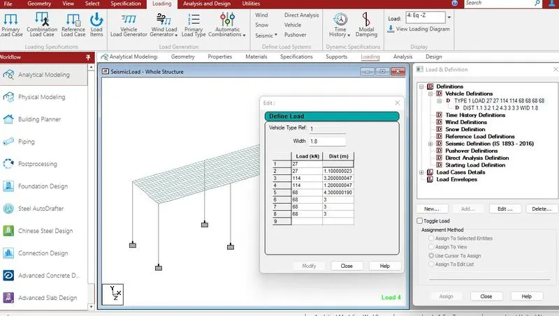
Class AA Loading detail
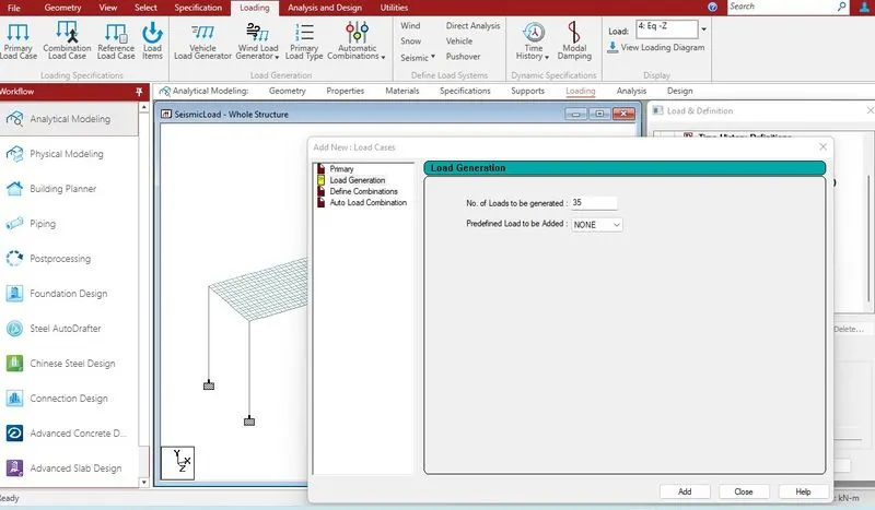
vehicle load generation
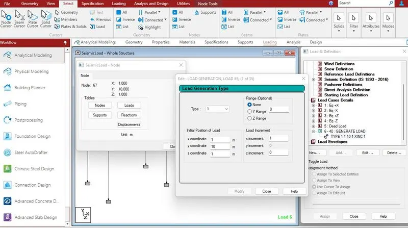
Placing 1st position
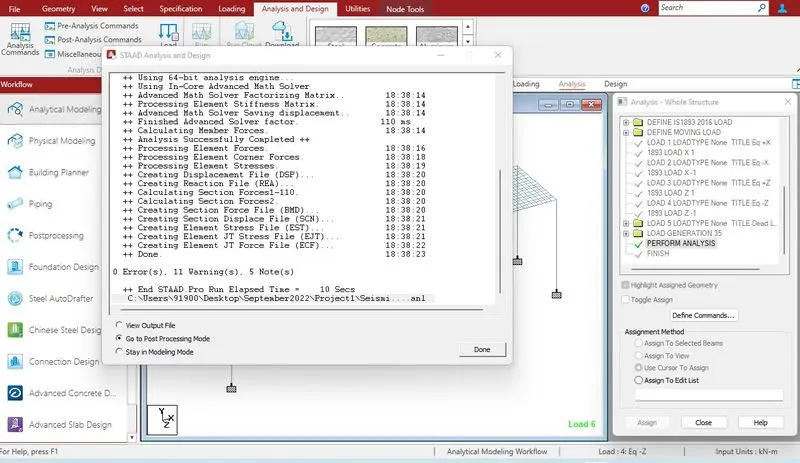
Design and analysis performed successfully
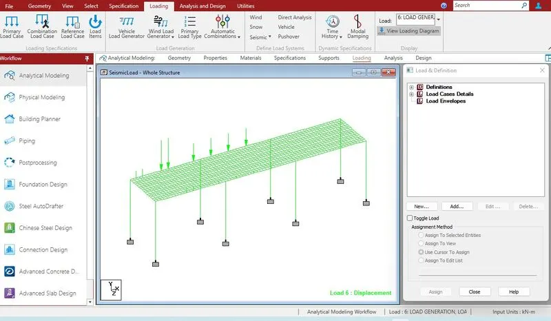
6th load generated
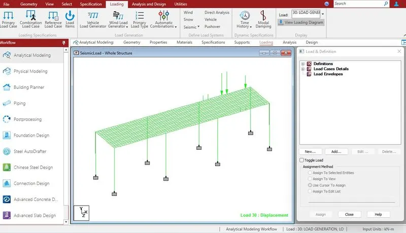
30th load generated by class AAvehicle
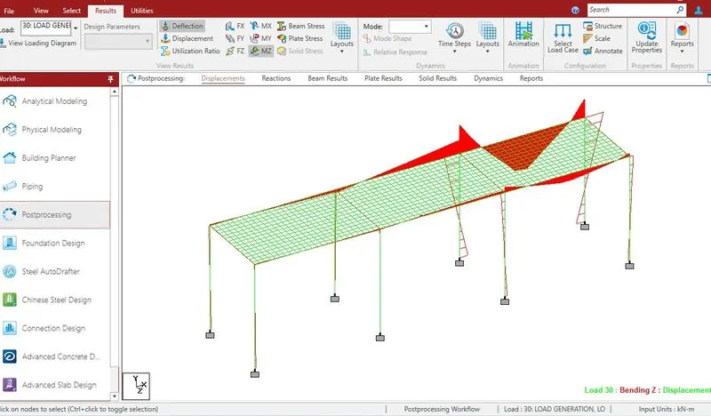
Bending moment due to 30th load generated by class AA vehicle
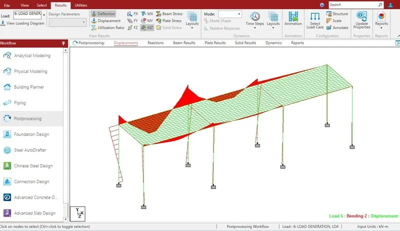 Bending moment due to moving load generated at 6th
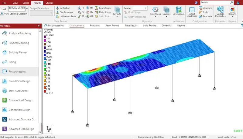 Plate stress due to moving load in 1st place
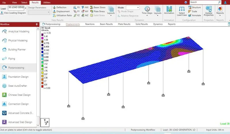
Bending moment MY local for moving load 30th position.
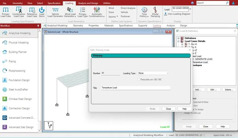
Tempreture load
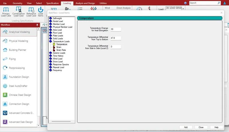
Tempreture for delhi input
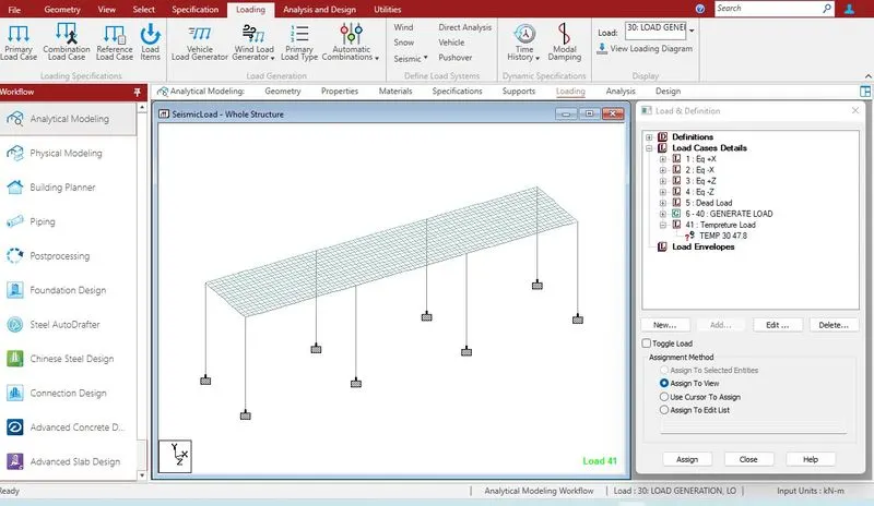
Assigned to whole structure
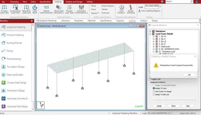
Tempreture load assigned
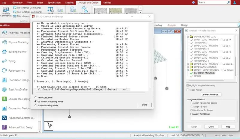
Design and analysis performed
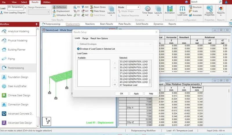
load selected
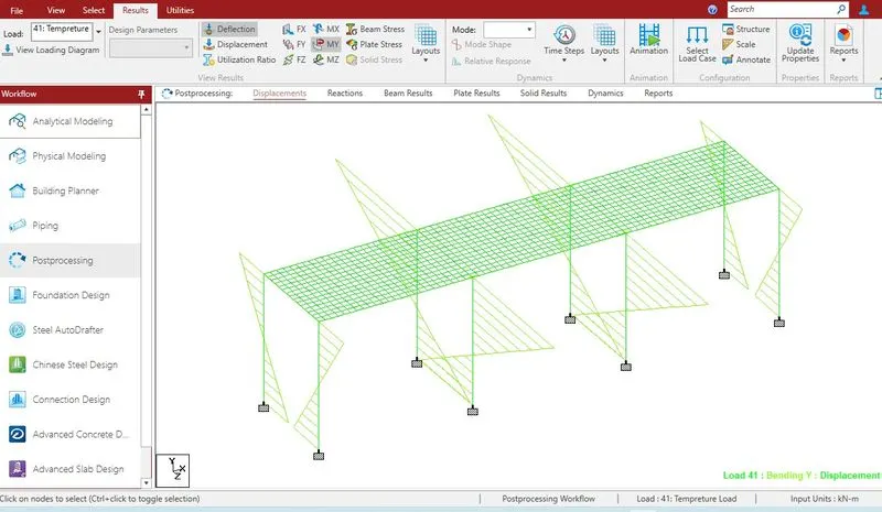
Bending moment MZ due to tempreture load
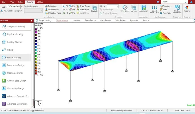
Plate stress MX local
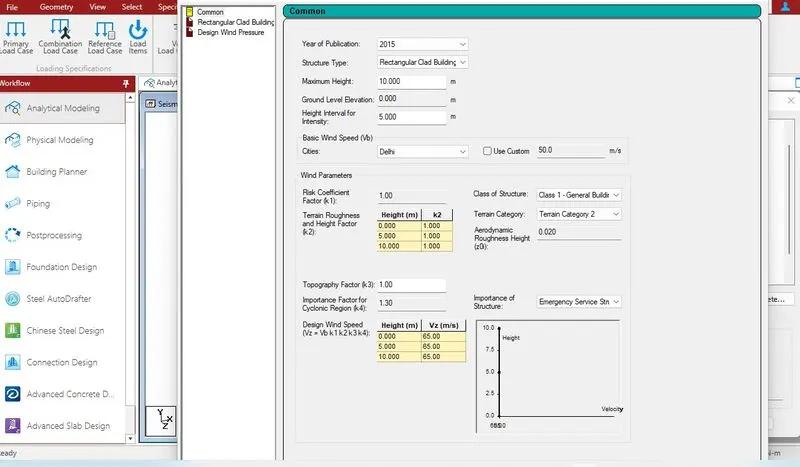
Wind load
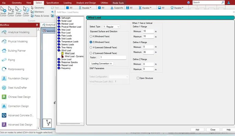
Range for Z direction.
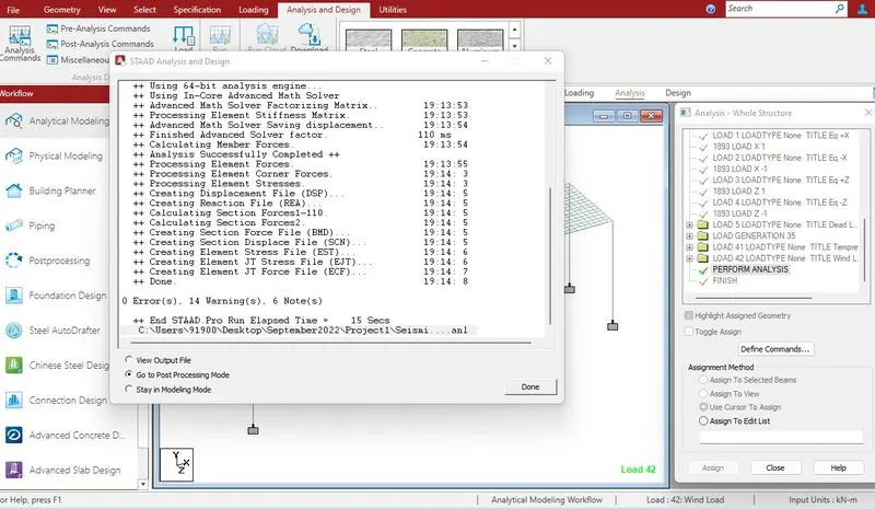
Design and analysis performed successfully
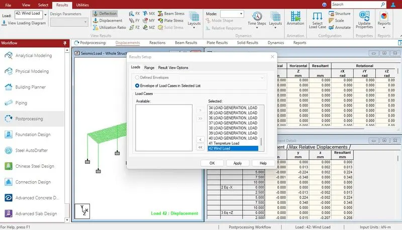
loads selected
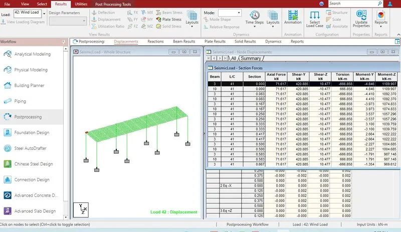
Report
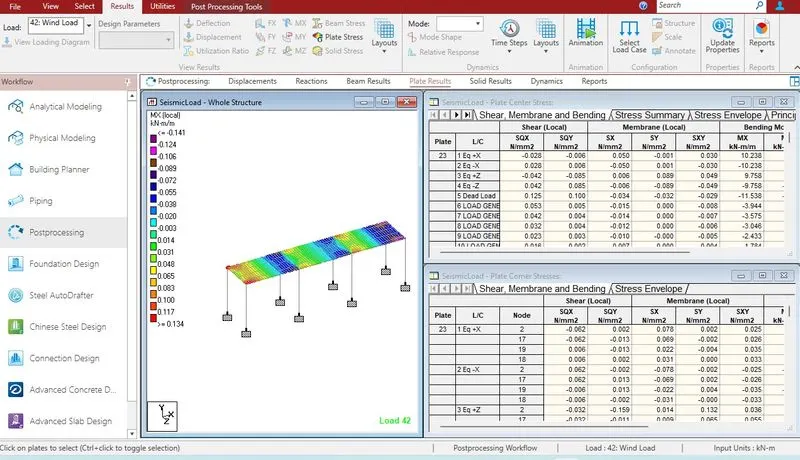
Plate stress MX local due to wind load
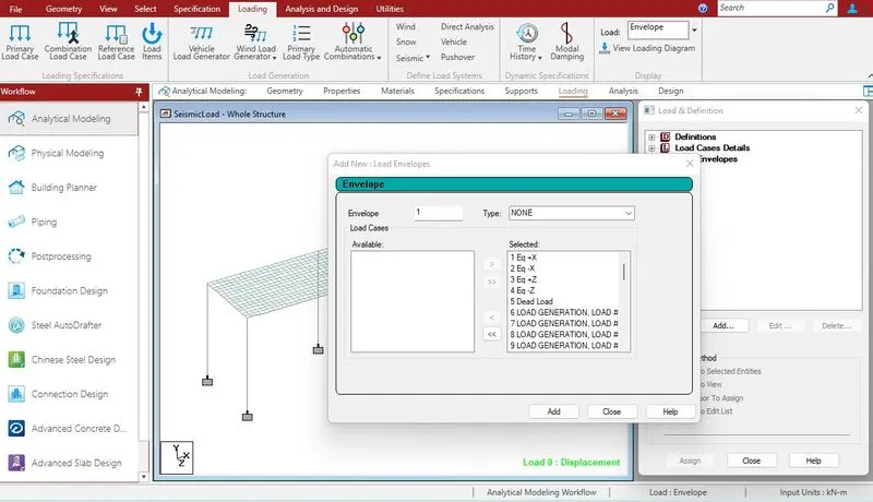
Load selected for envelope
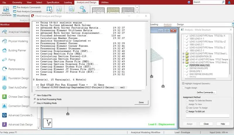
Design and analysis performed
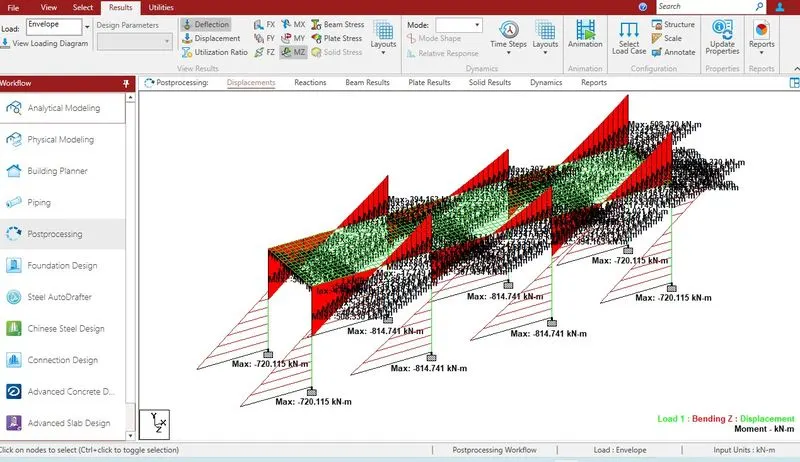
Bending moment for all loads
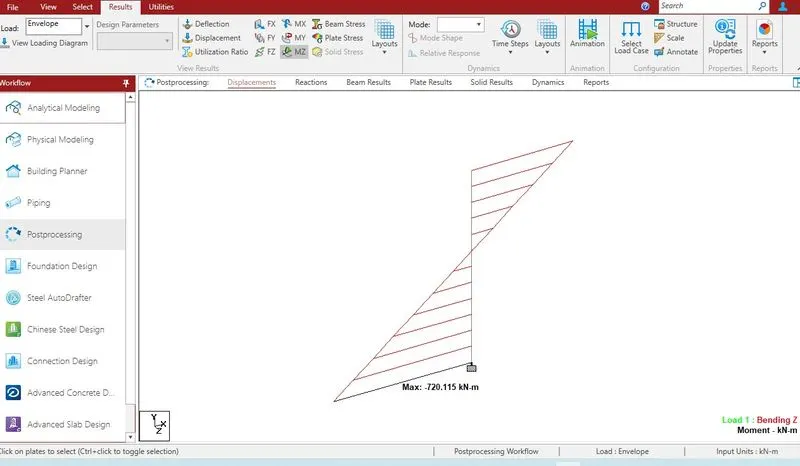
Maximum bending moment MZ on Pier
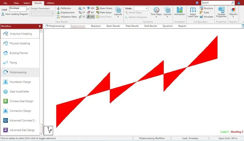
Bending moment on long girder
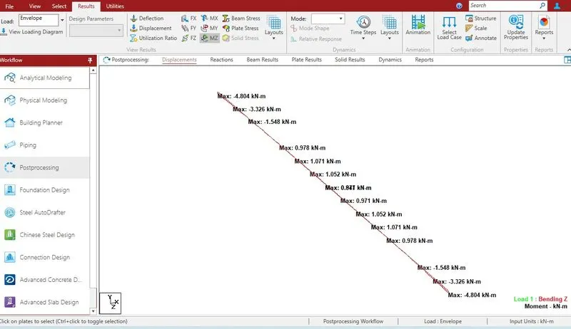
Bending moment on cross beam.
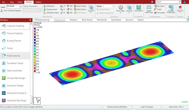
Plate load MX local.
Cl 214 IRC 6 EARTH PRESSURE
Earth pressure at rest When the verticle structural member is rigid and unyielding, the soil mass is in a state of rest and there will be no deformation and displacement
The earth pressure corresponding to this state is earth pressure at rest.
Cl 214.1.2.1 IRC 6 Active pressure due to earthfill
When the verticle structural member moves away from the backfill, the soil mass expands and decrease in pressure
The earth pressure corresponding to this state is called Active earth pressure
Cl 214.1.2.2 IRC 6 Passive pressure due to earthfill
When the verticle structural member moves towards the backfill, the soil mass compressed and the shear resistance developed towards the verticle member and there is increase in pressure
The earth pressure corresponding to this state is called Passive earth pressure