Week 1 Challenge
AIM:- The different type of foundation in bridge and All structural components of RCC girder bridge resting on open foundation.
Foundation:- A foundation is the element of a structure which connects it to the ground, transferring loads from the structure to the ground. Foundations are generally considered either shallow or deep
Types of foundation in bridge:-
1) Shallow foundations
2) Deep foundations
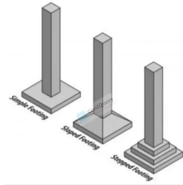
1) Shallow foundations:- Depth of the foundation is lesser than or equal to its breath. A shallow founadtion is a type of building foundation that transfers structural load to the earth very near to the surface ,
rather than to a subsurface layer or a range of depths, as does a deep foundation . Shallow foundations regularly have a wide base, which then, at that point moves the weight of the load onto the top soil.
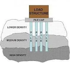
2) Deep foundation:- With a shallow foundations the actual soil worries about the concern. Deep foundations are generally thin and infiltrate through the top soil to deeper more grounded layers of soil. Here,
the vast majority of the help likewise comes from the grinding of soil pushing against the sides of the foundation.
Components of a RCC girder bridge:-
The main Components of a RCC girder bridge is
- Superstructure
- Substructure
- Foundation
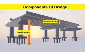
Superstructure:- The components of the bridge above bearing are known as superstructure.
- Deck Slab
- Girder
- Bearings
- Parapet Wall
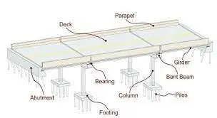
Deck Slab:-Superstructure consists of the deck slab ,Which supports the direct loads due to traffice and all the other to which the structure is subjected.
Girder:- The girder is basically a beam that supports other small beams and serves as the main horizontal supports of a structue.
The following types of girder in the bridges:-
- RCC I girder
- Precast PSC I girder
- Precast PSC Box girder
- U Type of girder
- Steel Plate girder
RCC I girder:- RCC girder bridge is most commonly adopted type in span range of 10 to 25 m. For the large spans the dead weight becomes too heavy. More space is provided at the bottom and top of the girder
for placing of reinforcement. RCC slab form a road deck to carry the traffic. The arrangement of the girder depends upon the carriage width of roadway.
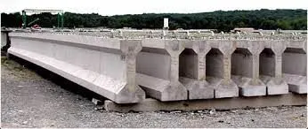
Precast PSC I girder:- Prestressed concrete provides great techical advantages in comparison with other types of construction such as steel and reinforced Concrete. For long span bridge the prestressed
concrete is more economical than reinforced concrete.
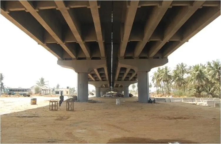
Precast PSC Box girder:- Box girders are used extensively in the construction of an elevated metro rail bridge and the use of horizontally curved in plan box girder bridges in modern metro rail system is quite
suitable in resisting torsional and warping effects induced by curvatures. The torsional and warping rigidity o box girder is due to the closed section of box girder. Box girder cross sections may take the form of
single cell,multi spine or multi cell. These types of structures can be generally used for spans 25m to 50m.
Type of Box girder
Single Cell Box girder
Multi Cell Box girder.
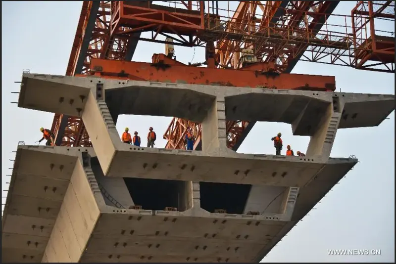
U type of girder :-The U shaped girder bridge is relatively new and innovation concept in bridge deck design.U- Shaped girder is appropriate when a new or modified aligment structure require an increase in the
vertical clearance beneath the bridge.The bridge deck made of prestressed concrete, has other important advantages such as reduced construction appearance, durability ad economy. this concept can be used
for overpasses, under- crossings , viaducts ,etc.
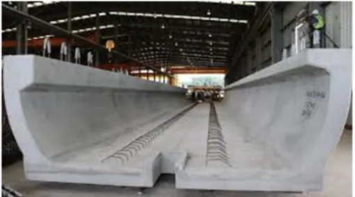
Steel Plate girder:- A plate girder is a steel beam that is widely used in bridge construction. Depending on the design requiments and as per the nature of the structure. In a plate girder, the plate girdes are
typically I beam made up from separate structural steel plates which are welded.
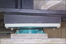
Bearing:-The connection between the substructure and the superstructure is usually made through bearings.A bearing is provided between the bridge girder and the pier cap.
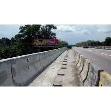
Parapet Wall:- They provide a passive line of defence. Properly Designed, they can reduce the severity of the consequence of an accident.
Substructure:- The structure of the bridge the levelnof bearings is known as the Substructre. The function of the substructure is to support the superstructure Components and transmit their loads safely o the
subsoil.
- Pier Cap
- Pier
- Abutment Wall
- Pile Cap
Pier Cap:-Pier caps are members which transfer the loads from the superstructure to the piers.They hold the bridge girders and bearing pds disperse the loads from the bearings to the piers.Bridge with piers will
have pier caps to transfer the load from the structure.
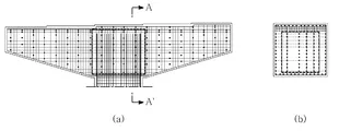
Pier :-piers provide intermediate support between two bridge Spans. Bridge piers mainly support the bridge superstructure element and transfer the load to the founadtion. pier must be strong to handle the
horizontal as well as well lateral. Piers are know as comperssion members of the bridge.
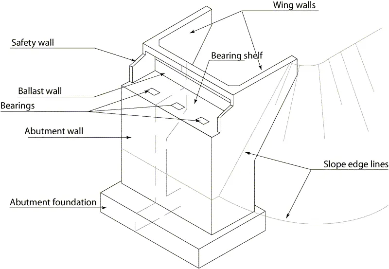
Abutment Wall:-It is a structure mostly used for bridge as a substrure at the ends of a bridge span superstructure rests on that.It also plays the role of retaining walls resist lateral movement of the earthen fillof
the bridge approach.
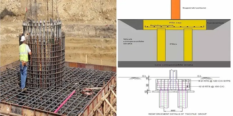
Pile Cap:-It is a structural member that is positioned and generally attached on the top of a pile or a group of piles to transfer the loads into the pile. Plie caps create a stable foundation and offer a larger area for
the distribution of the building load onto piles.To transfer the loads of the building to the founadations and the ground soil layers despite the loads are vertical or inclined.
Foundation:- The foundation carries the load of the superstructure,substructure and transfers it to the underlying hard ground. A foundation is the element of a structure which connects it to the ground,
transferring loads from the structure to the ground.
Forces acting on the shallow foundations
| Loads | Descripation | Direction |
| Dead Load | Weight of Structure and all permanently attached material | Vertical |
| Equipment and Instrumentation Load (E I) | Weight of the equipment's attached to the structure | Vertical |
| Live Load | Any Load not permanently attached to the structure may be subjected. | Vertical |
| Product Load | Any Load due to the weight of the hydrocarbon inside vessel/pipe. | Vertical |
| Friction Load | Load between the two weight of the hydrocarbon inside vessel/pipe. | Horizontal |
| Anchor Load | Restrained loa exerted by the pipe due to expansion | Horizontal/Vertical |
| Earthquake (E) | A lateral Force that acts on the structures | Horizontal |
| Snow load(S) | Acts on roofs | Vertical |
| Wind Load(W) | Acts on exposed parts of the structure | Horizontal |
| Thermal Load | Any loads exerted by the temperture | Horizontal |
| Soil Pressure and Buoyancy | Any loads due to earth pressures-commonly lateral but may be in the other directions | Horizontal/Vertical |
| Dynamic Startup/Shutdown | Any loads due to startup of a pump, may be either | Horizontal/Vertical |
Free Piers :- Free piers supports free bearings and transfer only axial forces from the bearing to the founadations.
Fixed Piers :- Fixed piers supports a fixed bearing and subjected both to transverse and longitudinal forces.
Abutment:- An Abutment is the substructure at the ends of a bridge span or dam supporting its superstrure.Single- Span bridge have abutments at each end which provide vertical and lateral support for the
span, as well as acting as retaining walls to resist lateral movement of the earthen fill of the bridge approach.Multi-span bridge require piers to supports ends of spans unspported by abutments.
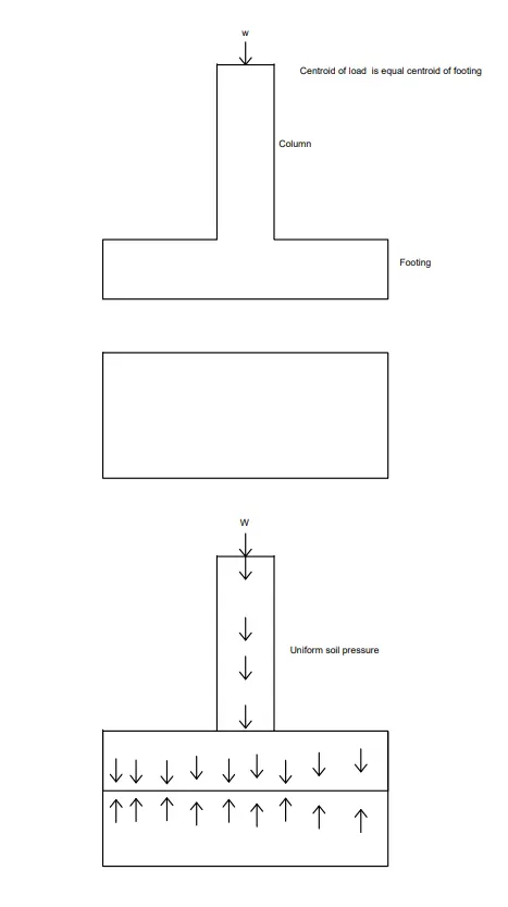
Concentric Footing:-The column is localized in center of the footing.Centroid of load is equal to the centroid of footing.
1.A centrally placed load W
Total Pressure = Load / Area
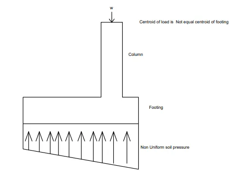
Eccentric Footing:-The eccentric footing is designed in such a way that the C.G of the superimposed load coincides with the C.G of the base area so, resulting in uniform bearing pressure.This footing is
subjected to concentric loading . It may not be possible to do so in some cases i.e. It will not be possible to spread the footing to both the sides of the wall or column under construction is near some other
property.
1.A centrally placed load W
2.A Bending moment whhich is M=W. e
where e is eccentricity.
Total Load= W +W.e
Total pressure = (Load / Area )+ (B.M. / Section Modulus)