Washing Machine model using Simulink Stateflow
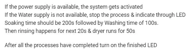
AIM : To implement control logic of a 'Washing Machine' using Stateflow as per following conditions :
SOLUTION :
(1) Washing Machine :
Stateflow model -
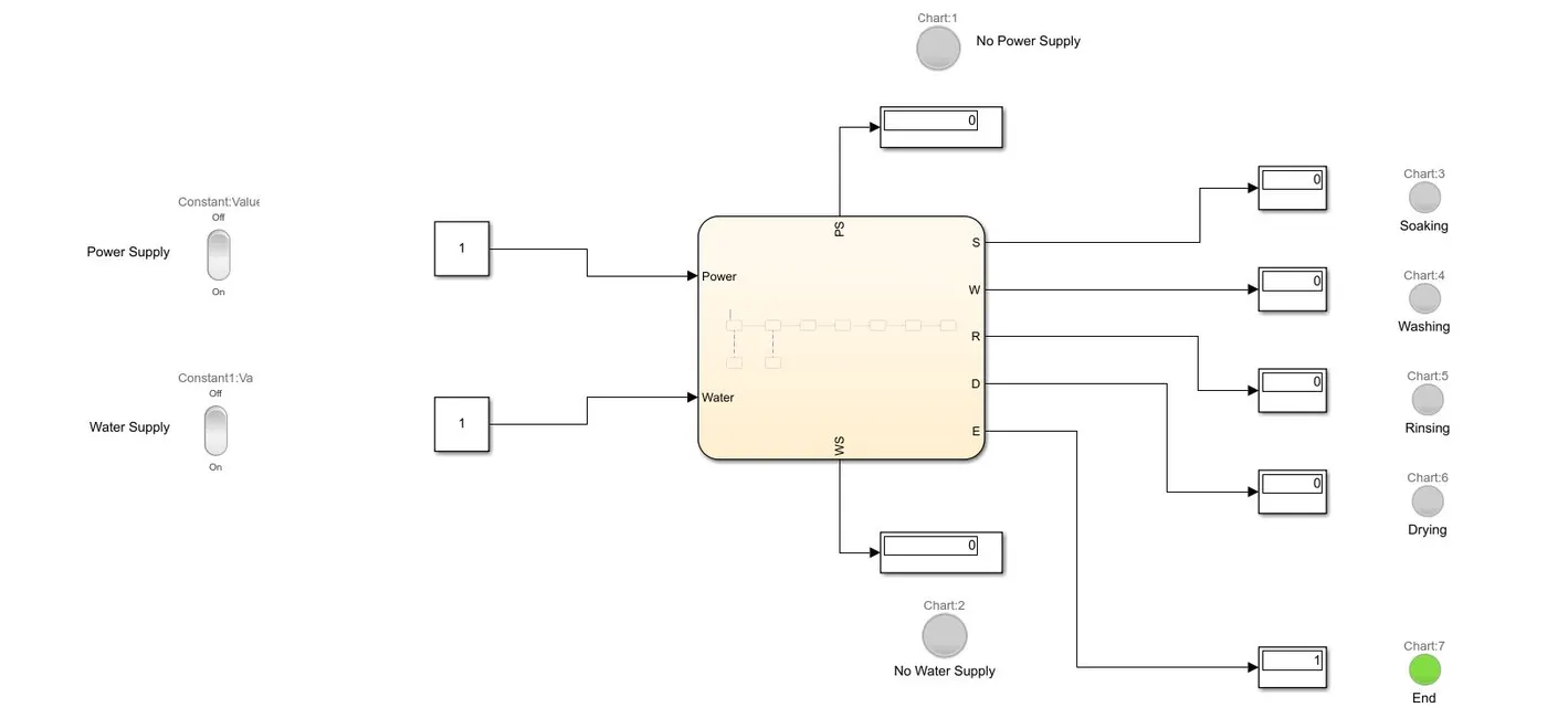
- The two inputs viz. Power supply and Water supply are controlled with the help of two Rocker Switches.
- This switches are connected to two separate Constant blocks.
- This connection is configured in such a way, that if the switch is on, the block shows 1. Similarly, if the switch is off, the block shows 0.
Stateflow Chart -
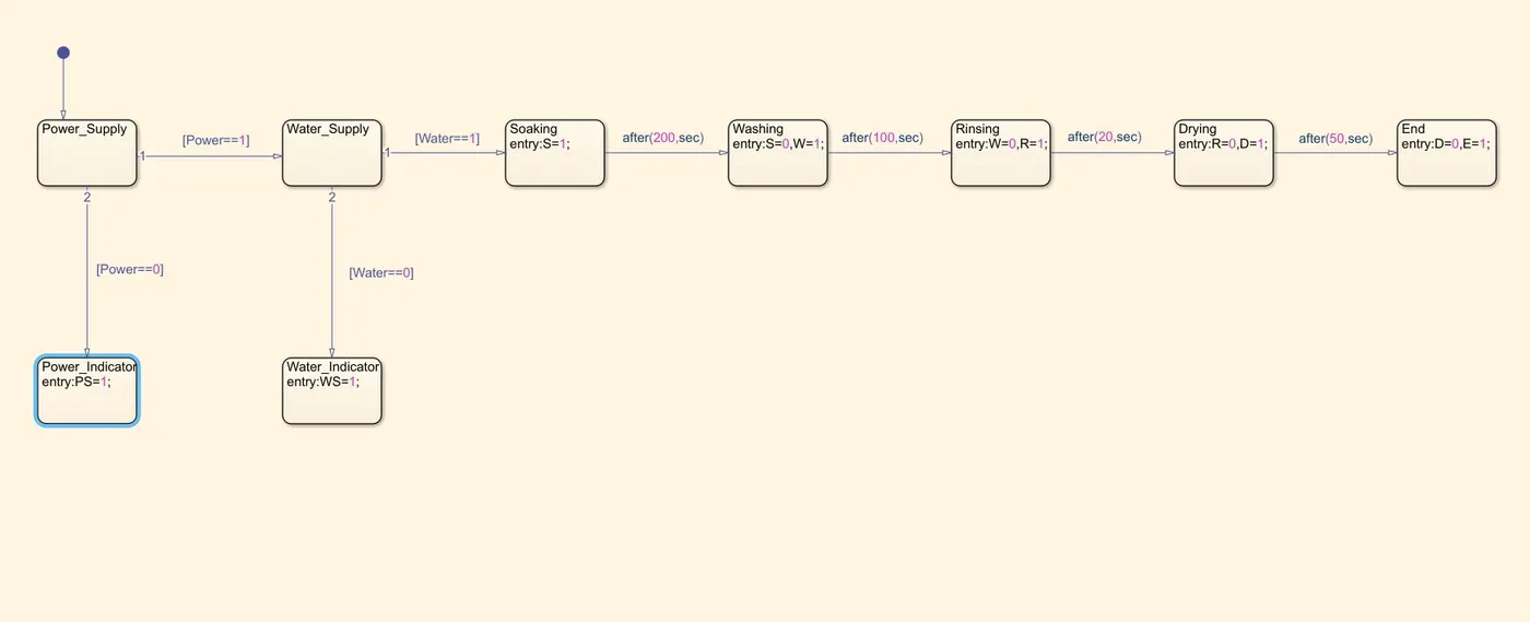
- To implement the required conditions, the Chart is added from the Simulink Library.
- Power is the most prime input needed for the running of the washing machine. Accordingly, the first State is provided regarding the power supply.
- Separate lamps are provided for each of the stages, to accurately denote the ongoing action.
- When all the stages are completed, the lamp corresponding to the End state glows.
- All these lamps are configured along with the respective display blocks in the similar way as done for the rocker switches.
Result :
a) When the Power supply is missing -
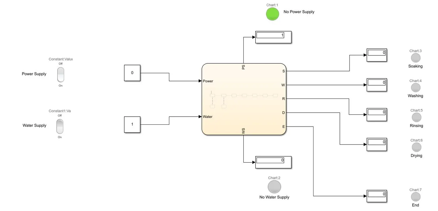
- The lamp corresponding to 'No Power Supply' is glowing.
b) When the Water Supply is missing -
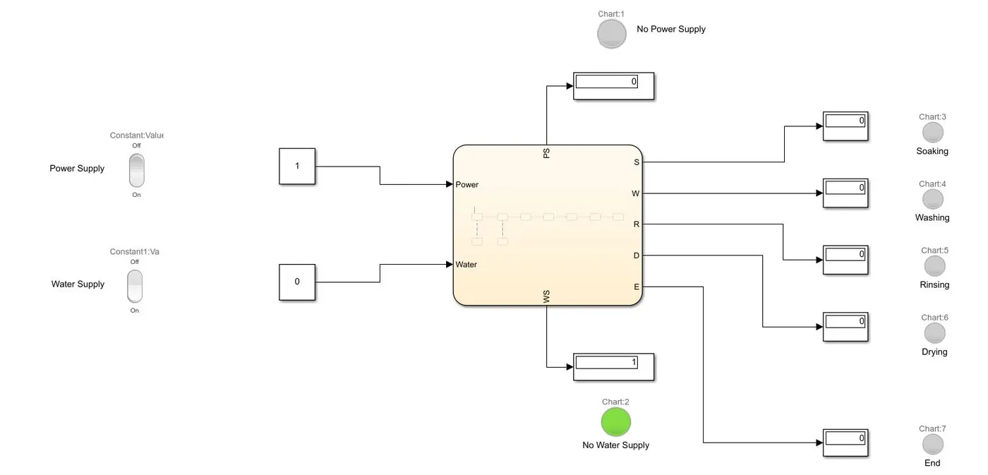
- The lamp corresponding to 'No Water Supply' is glowing.
c) When all the actions have been executed -
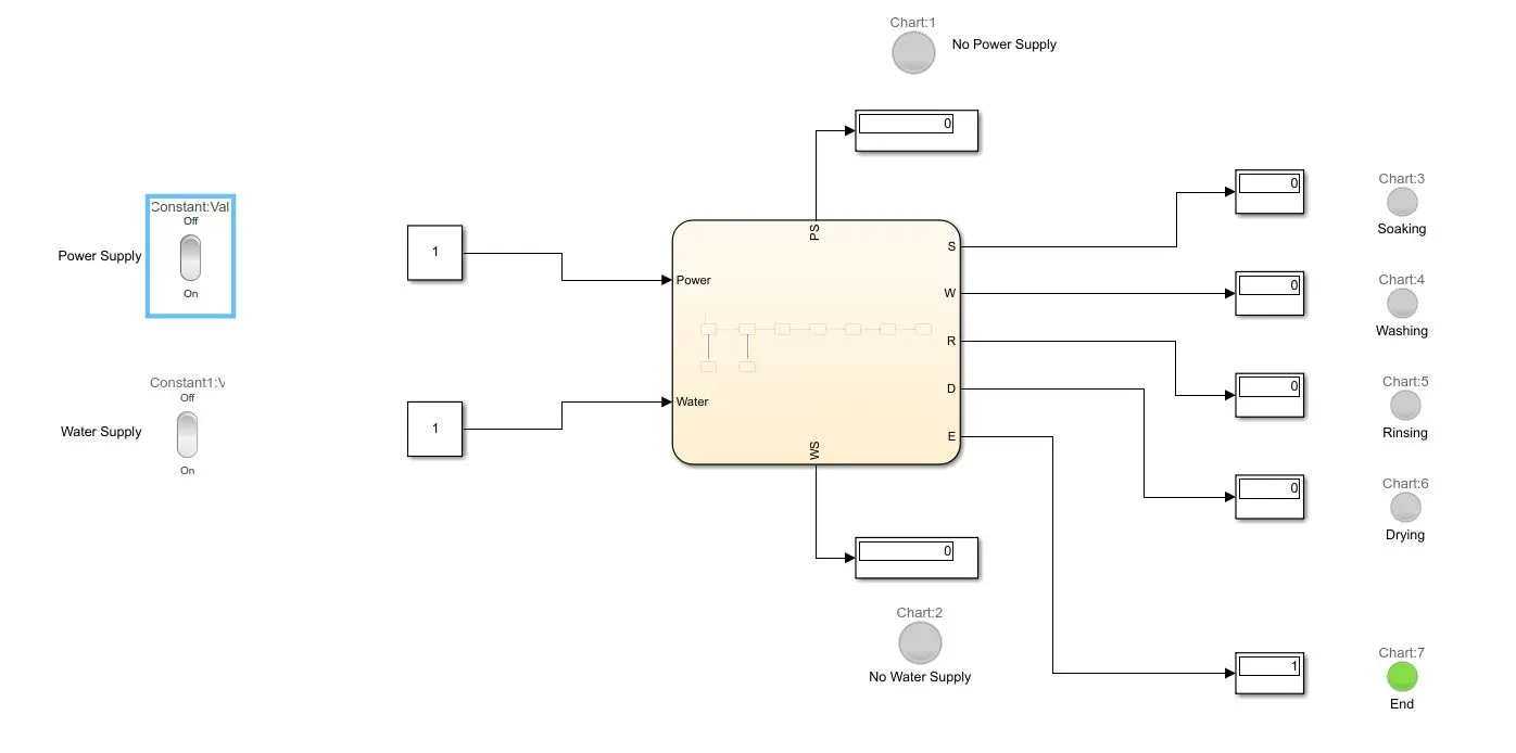
- The lamp corresponding to 'End' is glowing indicating all the processes have been executed properly.
https://drive.google.com/file/d/13XroNuhEDMkT6QWXYEPMrc1tG2ZPfOgJ/view?usp=sharing