Vehicle Direction Detection using the Stateflow chart in MATLAB - Simulink.
- Name of the project is Vehicle Direction Detection.
- Aim of the Project :- Development a MATLAB Simulink model of Vehicle Direction Detection and Perform MIL and SIL testing.
- Objective of the Project:
- Development of MATLAB Simulink model as per requirement.
- Tag the requirements to the simulink model; tagging requirement 1 & requirement 2 to their corresponding subsystems is fine.
- MBD compliant changes, Data Dictionary creation & code generation is added advantage, and that is not scope of this project.
- If choosing code generation, Storage class for Input signals: ImportedExtern; Storage class for Output signal: Export to File; Storage class for local signals: localizable; Storage class for calibration signals: Const.
- Choose sample time for all signals as 0.01s
- Requirement of the project :
- Requirement - 1:
- Steering wheel input as yaw rate (Signal name: SteeringWheel_YawDegreeInput) is the input for this system.
- This is compared against 3 angular values, one each for left turn, right turn & straight drive (Calibration Values: Right_Turn_AngularLimit, Left_Turn_AngularLimit, Straight_Drive_Steering_Angle) to say which specific direction the steering wheel is turning towards.
- Use switch blocks to compare & develop this requirement. Keep this requirement in a subsystem & output of this requirement is a local signal (Signal Name: Vehicle_Turn_Status).
- Requirement – 2:
- Keep this requirement as a separate subsystem. Inputs to this requirement are local signal from requirement 1 (Signal Name: Vehicle_Turn_Status) & an input signal from camera (Signal Name: CameraInput_RoadSign), which confirms the occurrence of a road sign.
- Signal Vehicle_Turn_Status is compared against calibration values (Calibration Values: RightTurn_RoadSign, LeftTurn_RoadSign, Straight_RoadSign), if each of them is found equal, then each of the three corresponding output is compared against the camera input signal,
- Using a logical operator block, only one among them is finally given as output signal (Signal Name: Vehicle_Direction_Indicator).
- MATLAB Simulink model for Vehicle Direction Detection
- This is a base model.
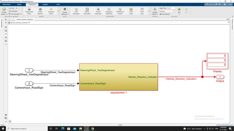
- There is three different models for shown here as per given requirements.
- Right Turn
- Straight drive
- Left Turn
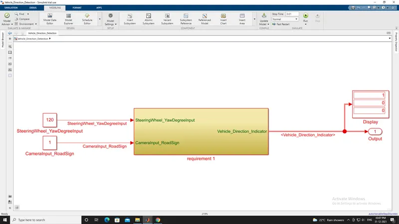
- Right Turn
- Here, Input values are constant block one is Steering Wheel input (which is 120 degree) and Other one is Camera input (Which is 1. Boolean data type means input is 0 or 1).
- Output signal (Signal Name: Vehicle_Direction_Indicator) which is 1 0 0 means Right Turn.
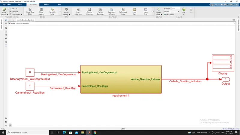
- Straight drive
- Here, Input values are constant block one is Steering Wheel input (which is 0 degree) and Other one is Camera input (Which is 1. Boolean data type means input is 0 or 1).
- Output signal (Signal Name: Vehicle_Direction_Indicator) which is 0 1 0 means Straight Turn.
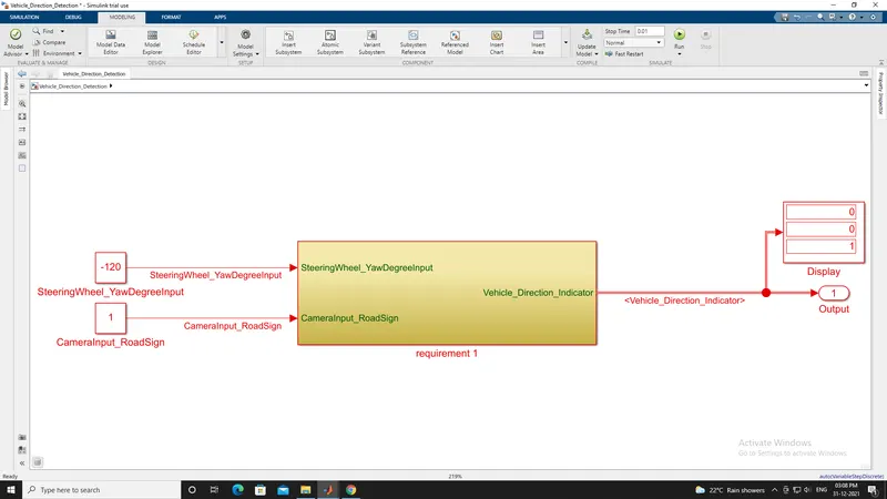
- Left Turn
- Here, Input values are constant block one is Steering Wheel input (which is -120 degree) and Other one is Camera input (Which is boolean data type means input is 0 or 1).
- Output signal (Signal Name: Vehicle_Direction_Indicator) which is 0 0 1 means Left Turn.
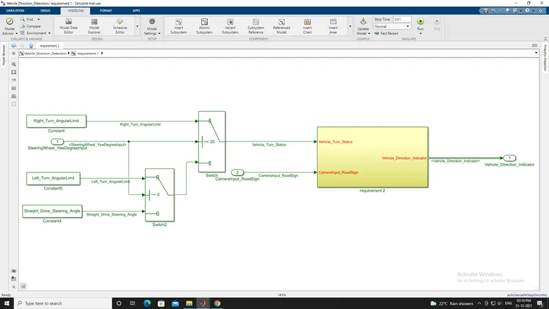
- This is a subsystem 1 as per requirement 1.
- As per Steering Wheel input (Switch block is use for a toggle switch that selects one of its two inputs to pass through to the output.) decide the vehicle turn status (Output) in this subsystem.
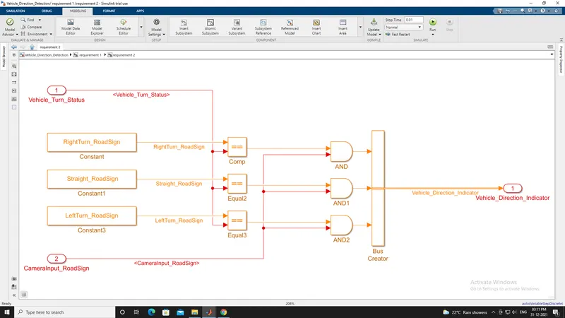
- This is a subsystem 2 as per requirement 2.
- Here input is the vehicle turn status is compared against calibration values with using relational operators
- There output is compared against the camera input (Road sign data) signal with the help of logical operators.
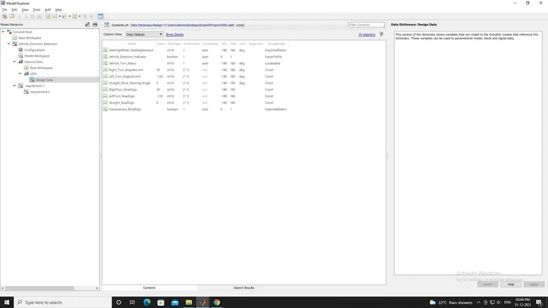
- Signals & Calibration Data List:
- SLDD file for Vehicle Direction Detection.
- Model In Loop (MIL) Testing :-
- Model-in-the-loop testing (MIL) and simulation is a technique used to abstract the behaviour of a system or sub-system in a way that this model can be used to test, simulate and verify that model.
- First, you have to develop a model of the actual plant (hardware) in a simulation environment such as Simulink, which captures most of the important features of the hardware system. After the plant model is created, develop the controller model and verify if the controller can control the plant (which is the model of the motor in this case) as per the requirement. This step is called Model-in-Loop (MIL) and you are testing the controller logic on the simulated model of the plant. If your controller works as desired, you should record the input and output of the controller which will be used in the later stage of verification.
-
Model-in-Loop testing, also called MiL testing or model testing, is the testing of single or integrated modules in a model-based development environment, such as MATLAB Simulink from Mathworks or ASCET from ETAS.
-
When developing a system, a model-based design (MBD) allows early identification and correction of errors and bugs because the models can be simulated easily in a very early design phase. Due to its early development stage, testing iterations (“loops”) can be finalized much faster than in longer (later) development stages. This approach is therefore a cost-efficient way to reduce development time significantly. Additionally, the graphical approach of programming is intuitive and loved by engineers.
-
Model-in-Loop testing is also related to unit testing, while the units under test are “model units”.
-
The MBD approach, and thus MiL testing, is commonly used in the automotive industry. Development processes used in MBD can be fully compliant with safety norms such as e.g. ISO26262 or IEC61508. These norms usually require MiL testing in early design phases.
-
The test level following MiL testing is Software-in-Loop testing (SiL testing) using software that is generated, oftentimes automatically, directly from the models, or written manually in C-code. For this test level, auto code generation is used. Common C-code generators for Simulink models are dSpace TargetLink or Mathworks Embedded Coder. Once both MiL and SiL testing phases are done, the individual test results can be tested “back-to-back”. Back-to-back testing is used for the comparison of test results between MiL and SiL testing.
- Software In Loop (SIL) Testing :-
- Once your model has been verified in MIL simulation, the next stage is Software-in-Loop(SIL), where you generate code only from the controller model and replace the controller block with this code. Then run the simulation with the Controller block (which contains the C code) and the Plant, which is still the software model (similar to the first step). This step will give you an idea of whether your control logic i.e., the Controller model can be converted to code and if it is hardware implementable. You should log the input-output here and match it with what you have achieved in the previous step. If you experience a huge difference in them, you may have to go back to MIL and make necessary changes and then repeat steps 1 and 2. If you have a model which has been tested for SIL and the performance is acceptable you can move forward to the next step.
- This SIL model is created by Simulink it self.
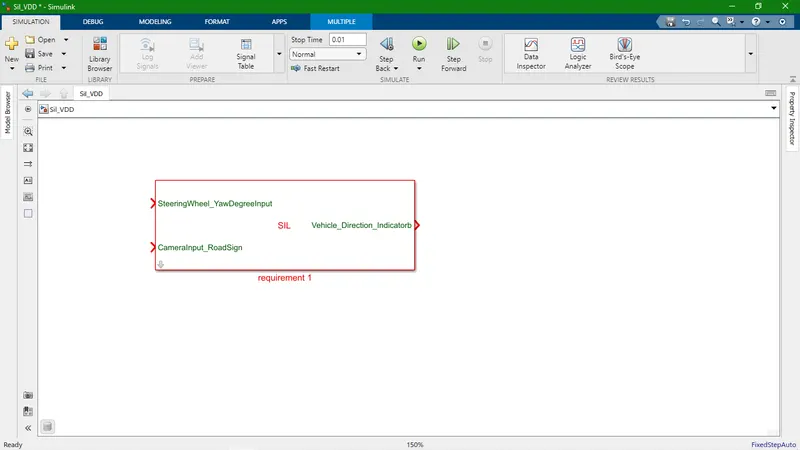
- This is location of SIL model.
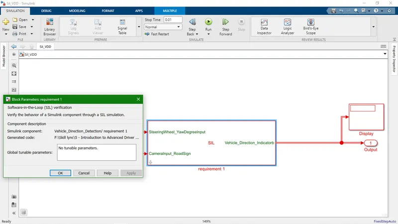
- This is a first subsystem which is according to requirement one.
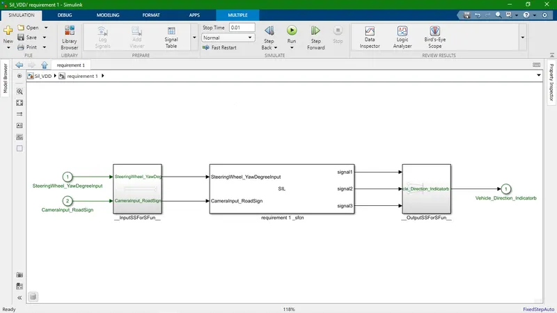
- This is another subsystem.
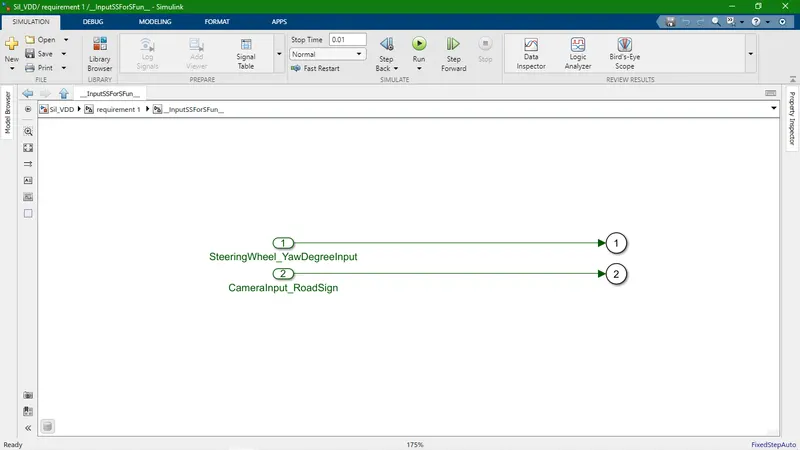
- This is also another subsystem and it gives output.
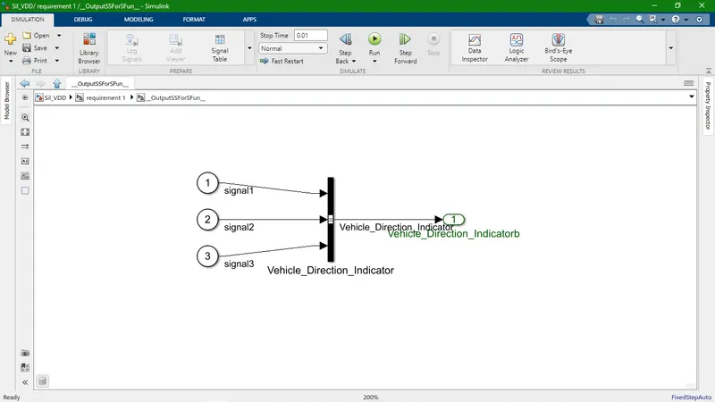
- There is three different models for shown here as per given requirements.
- Right Turn
- Straight Turn
- Left Turn
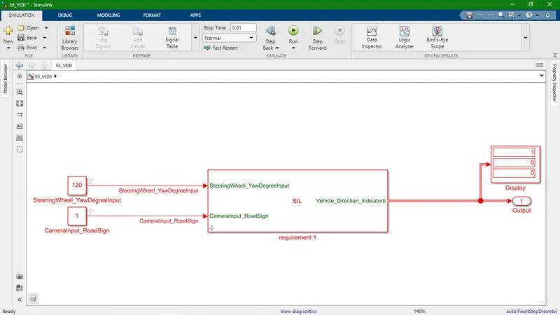
- Right Turn
- Here, Input values are constant block one is Steering Wheel input (which is 120 degree) and Other one is Camera input (Which is 1. Boolean data type means input is 0 or 1).
- Output signal (Signal Name: Vehicle_Direction_Indicator) which is 1 0 0 means Right Turn.
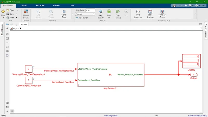
- Straight drive
- Here, Input values are constant block one is Steering Wheel input (which is 0 degree) and Other one is Camera input (Which is 1. Boolean data type means input is 0 or 1).
- Output signal (Signal Name: Vehicle_Direction_Indicator) which is 0 1 0 means Straight Turn.
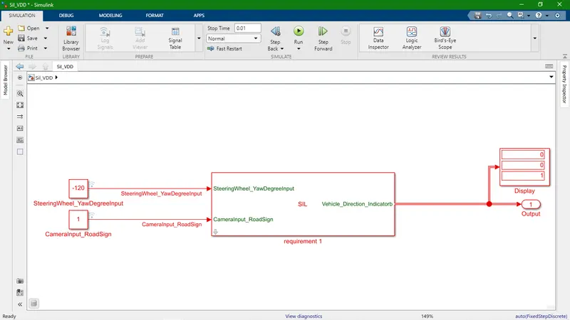
- Left Turn
- Here, Input values are constant block one is Steering Wheel input (which is -120 degree) and Other one is Camera input (Which is boolean data type means input is 0 or 1).
- Output signal (Signal Name: Vehicle_Direction_Indicator) which is 0 0 1 means Left Turn.
- C Code
/*
* File: ert_main.c
*
* Code generated for Simulink model 'requirement'.
*
* Model version : 1.59
* Simulink Coder version : 9.5 (R2021a) 14-Nov-2020
* C/C++ source code generated on : Wed Jan 19 13:53:31 2022
*
* Target selection: ert.tlc
* Embedded hardware selection: Intel->x86-64 (Windows64)
* Code generation objectives: Unspecified
* Validation result: Not run
*/
#include
#include /* This ert_main.c example uses printf/fflush */
#include "requirement.h" /* Model's header file */
#include "rtwtypes.h"
/*
* Associating rt_OneStep with a real-time clock or interrupt service routine
* is what makes the generated code "real-time". The function rt_OneStep is
* always associated with the base rate of the model. Subrates are managed
* by the base rate from inside the generated code. Enabling/disabling
* interrupts and floating point context switches are target specific. This
* example code indicates where these should take place relative to executing
* the generated code step function. Overrun behavior should be tailored to
* your application needs. This example simply sets an error status in the
* real-time model and returns from rt_OneStep.
*/
void rt_OneStep(void);
void rt_OneStep(void)
{
static boolean_T OverrunFlag = false;
/* Disable interrupts here */
/* Check for overrun */
if (OverrunFlag) {
rtmSetErrorStatus(requirement_M, "Overrun");
return;
}
OverrunFlag = true;
/* Save FPU context here (if necessary) */
/* Re-enable timer or interrupt here */
/* Set model inputs here */
/* Step the model */
requirement_step();
/* Get model outputs here */
/* Indicate task complete */
OverrunFlag = false;
/* Disable interrupts here */
/* Restore FPU context here (if necessary) */
/* Enable interrupts here */
}
/*
* The example "main" function illustrates what is required by your
* application code to initialize, execute, and terminate the generated code.
* Attaching rt_OneStep to a real-time clock is target specific. This example
* illustrates how you do this relative to initializing the model.
*/
int_T main(int_T argc, const char *argv[])
{
/* Unused arguments */
(void)(argc);
(void)(argv);
/* Initialize model */
requirement_initialize();
/* Attach rt_OneStep to a timer or interrupt service routine with
* period 0.0002 seconds (the model's base sample time) here. The
* call syntax for rt_OneStep is
*
* rt_OneStep();
*/
printf("Warning: The simulation will run forever. "
"Generated ERT main won't simulate model step behavior. "
"To change this behavior select the 'MAT-file logging' option.n");
fflush((NULL));
while (rtmGetErrorStatus(requirement_M) == (NULL)) {
/* Perform other application tasks here */
}
/* Disable rt_OneStep() here */
/* Terminate model */
requirement_terminate();
return 0;
}
/*
* File trailer for generated code.
*
* [EOF]
*/
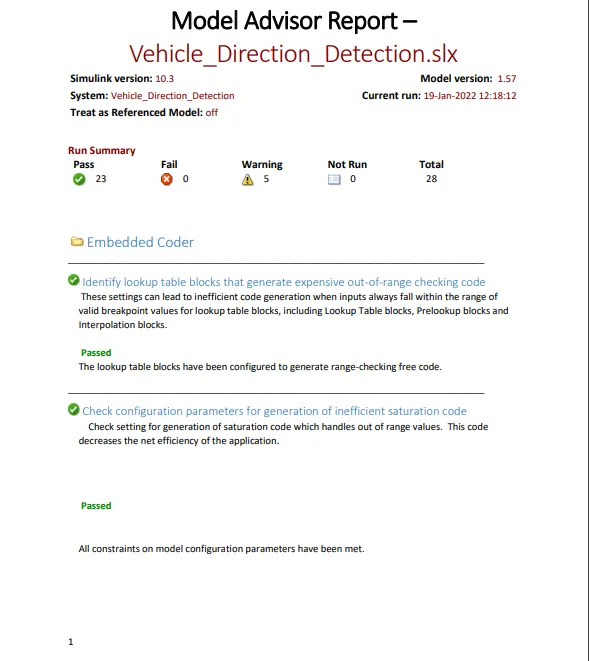
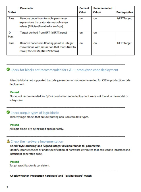
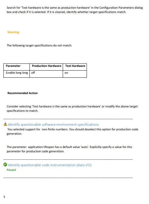
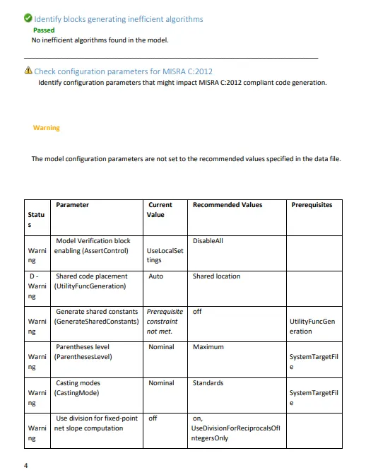
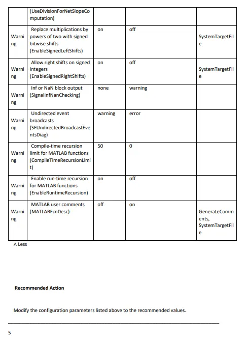
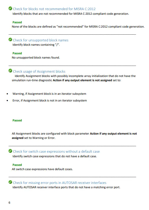
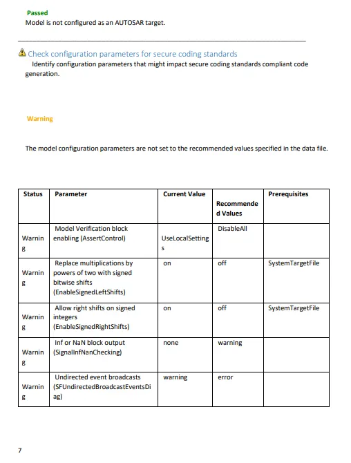
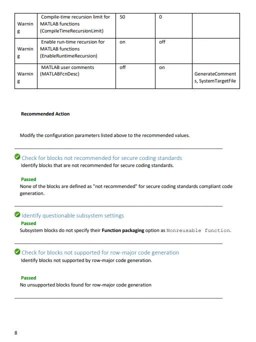
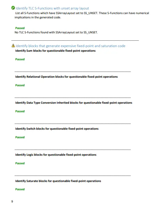
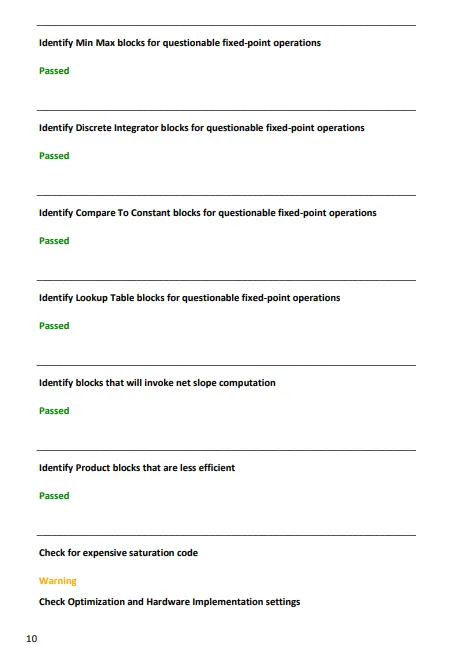
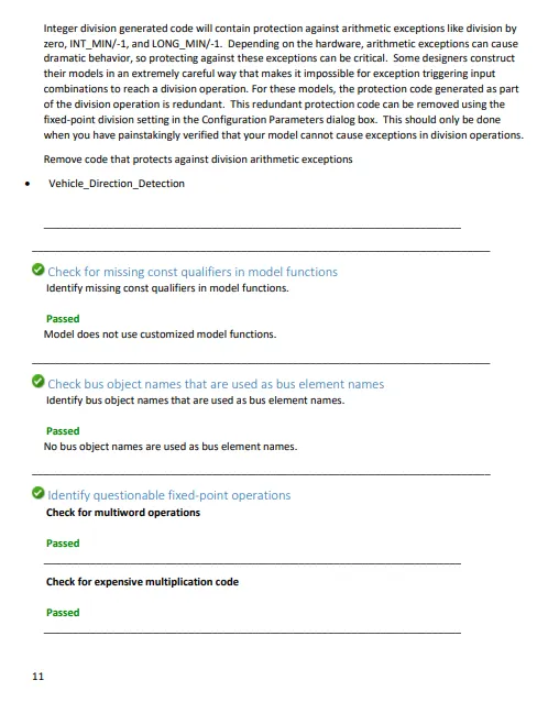
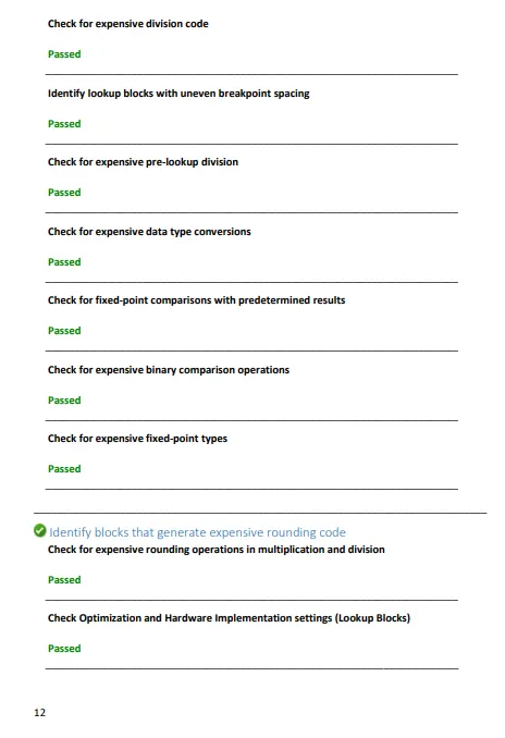
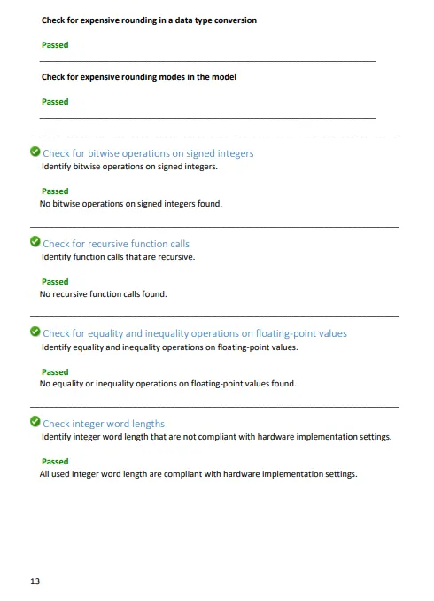
- This is a report of model advisor.
- Note :- Code generation file is given below.
/*
* File: ert_main.c
*
* Code generated for Simulink model 'Vehicle_Direction_Detection'.
*
* Model version : 1.57
* Simulink Coder version : 9.5 (R2021a) 14-Nov-2020
* C/C++ source code generated on : Wed Jan 19 12:10:55 2022
*
* Target selection: ert.tlc
* Embedded hardware selection: Intel->x86-64 (Windows64)
* Code generation objectives: Unspecified
* Validation result: Not run
*/
#include
#include /* This ert_main.c example uses printf/fflush */
#include "Vehicle_Direction_Detection.h" /* Model's header file */
#include "rtwtypes.h"
/*
* Associating rt_OneStep with a real-time clock or interrupt service routine
* is what makes the generated code "real-time". The function rt_OneStep is
* always associated with the base rate of the model. Subrates are managed
* by the base rate from inside the generated code. Enabling/disabling
* interrupts and floating point context switches are target specific. This
* example code indicates where these should take place relative to executing
* the generated code step function. Overrun behavior should be tailored to
* your application needs. This example simply sets an error status in the
* real-time model and returns from rt_OneStep.
*/
void rt_OneStep(void);
void rt_OneStep(void)
{
static boolean_T OverrunFlag = false;
/* Disable interrupts here */
/* Check for overrun */
if (OverrunFlag) {
rtmSetErrorStatus(Vehicle_Direction_Detection_M, "Overrun");
return;
}
OverrunFlag = true;
/* Save FPU context here (if necessary) */
/* Re-enable timer or interrupt here */
/* Set model inputs here */
/* Step the model */
Vehicle_Direction_Detection_step();
/* Get model outputs here */
/* Indicate task complete */
OverrunFlag = false;
/* Disable interrupts here */
/* Restore FPU context here (if necessary) */
/* Enable interrupts here */
}
/*
* The example "main" function illustrates what is required by your
* application code to initialize, execute, and terminate the generated code.
* Attaching rt_OneStep to a real-time clock is target specific. This example
* illustrates how you do this relative to initializing the model.
*/
int_T main(int_T argc, const char *argv[])
{
/* Unused arguments */
(void)(argc);
(void)(argv);
/* Initialize model */
Vehicle_Direction_Detection_initialize();
/* Attach rt_OneStep to a timer or interrupt service routine with
* period 0.0002 seconds (the model's base sample time) here. The
* call syntax for rt_OneStep is
*
* rt_OneStep();
*/
printf("Warning: The simulation will run forever. "
"Generated ERT main won't simulate model step behavior. "
"To change this behavior select the 'MAT-file logging' option.n");
fflush((NULL));
while (rtmGetErrorStatus(Vehicle_Direction_Detection_M) == (NULL)) {
/* Perform other application tasks here */
}
/* Disable rt_OneStep() here */
/* Terminate model */
Vehicle_Direction_Detection_terminate();
return 0;
}
/*
* File trailer for generated code.
*
* [EOF]
*/
---------------------------------------------
/*
* File: ert_main.c
*
* Code generated for Simulink model 'Vehicle_Direction_Detection'.
*
* Model version : 1.57
* Simulink Coder version : 9.5 (R2021a) 14-Nov-2020
* C/C++ source code generated on : Wed Jan 19 12:10:55 2022
*
* Target selection: ert.tlc
* Embedded hardware selection: Intel->x86-64 (Windows64)
* Code generation objectives: Unspecified
* Validation result: Not run
*/
#include
#include /* This ert_main.c example uses printf/fflush */
#include "Vehicle_Direction_Detection.h" /* Model's header file */
#include "rtwtypes.h"
/*
* Associating rt_OneStep with a real-time clock or interrupt service routine
* is what makes the generated code "real-time". The function rt_OneStep is
* always associated with the base rate of the model. Subrates are managed
* by the base rate from inside the generated code. Enabling/disabling
* interrupts and floating point context switches are target specific. This
* example code indicates where these should take place relative to executing
* the generated code step function. Overrun behavior should be tailored to
* your application needs. This example simply sets an error status in the
* real-time model and returns from rt_OneStep.
*/
void rt_OneStep(void);
void rt_OneStep(void)
{
static boolean_T OverrunFlag = false;
/* Disable interrupts here */
/* Check for overrun */
if (OverrunFlag) {
rtmSetErrorStatus(Vehicle_Direction_Detection_M, "Overrun");
return;
}
OverrunFlag = true;
/* Save FPU context here (if necessary) */
/* Re-enable timer or interrupt here */
/* Set model inputs here */
/* Step the model */
Vehicle_Direction_Detection_step();
/* Get model outputs here */
/* Indicate task complete */
OverrunFlag = false;
/* Disable interrupts here */
/* Restore FPU context here (if necessary) */
/* Enable interrupts here */
}
/*
* The example "main" function illustrates what is required by your
* application code to initialize, execute, and terminate the generated code.
* Attaching rt_OneStep to a real-time clock is target specific. This example
* illustrates how you do this relative to initializing the model.
*/
int_T main(int_T argc, const char *argv[])
{
/* Unused arguments */
(void)(argc);
------------------------------------------------------------------------------------------------------
/*
* File: ert_main.c
*
* Code generated for Simulink model 'Vehicle_Direction_Detection'.
*
* Model version : 1.57
* Simulink Coder version : 9.5 (R2021a) 14-Nov-2020
* C/C++ source code generated on : Wed Jan 19 12:10:55 2022
*
* Target selection: ert.tlc
* Embedded hardware selection: Intel->x86-64 (Windows64)
* Code generation objectives: Unspecified
* Validation result: Not run
*/
#include
#include /* This ert_main.c example uses printf/fflush */
#include "Vehicle_Direction_Detection.h" /* Model's header file */
#include "rtwtypes.h"
/*
* Associating rt_OneStep with a real-time clock or interrupt service routine
* is what makes the generated code "real-time". The function rt_OneStep is
* always associated with the base rate of the model. Subrates are managed
* by the base rate from inside the generated code. Enabling/disabling
* interrupts and floating point context switches are target specific. This
* example code indicates where these should take place relative to executing
* the generated code step function. Overrun behavior should be tailored to
* your application needs. This example simply sets an error status in the
* real-time model and returns from rt_OneStep.
*/
void rt_OneStep(void);
void rt_OneStep(void)
{
static boolean_T OverrunFlag = false;
/* Disable interrupts here */
/* Check for overrun */
if (OverrunFlag) {
rtmSetErrorStatus(Vehicle_Direction_Detection_M, "Overrun");
return;
}
OverrunFlag = true;
/* Save FPU context here (if necessary) */
/* Re-enable timer or interrupt here */
/* Set model inputs here */
/* Step the model */
Vehicle_Direction_Detection_step();
/* Get model outputs here */
/* Indicate task complete */
OverrunFlag = false;
/* Disable interrupts here */
/* Restore FPU context here (if necessary) */
/* Enable interrupts here */
}
/*
* The example "main" function illustrates what is required by your
* application code to initialize, execute, and terminate the generated code.
* Attaching rt_OneStep to a real-time clock is target specific. This example
* illustrates how you do this relative to initializing the model.
*/
int_T main(int_T argc, const char *argv[])
{
/* Unused arguments */
(void)(argc);
(void)(argv);
/* Initialize model */
Vehicle_Direction_Detection_initialize();
/* Attach rt_OneStep to a timer or interrupt service routine with
* period 0.0002 seconds (the model's base sample time) here. The
* call syntax for rt_OneStep is
*
* rt_OneStep();
*/
------------------------------------------------------------------------------------------------------
/*
* File: Vehicle_Direction_Detection.c
*
* Code generated for Simulink model 'Vehicle_Direction_Detection'.
*
* Model version : 1.57
* Simulink Coder version : 9.5 (R2021a) 14-Nov-2020
* C/C++ source code generated on : Wed Jan 19 12:10:55 2022
*
* Target selection: ert.tlc
* Embedded hardware selection: Intel->x86-64 (Windows64)
* Code generation objectives: Unspecified
* Validation result: Not run
*/
#include "Vehicle_Direction_Detection.h"
#include "Vehicle_Direction_Detection_private.h"
/* Exported data definition */
/* Const memory section */
/* Definition for custom storage class: Const */
const int16_T LeftTurn_RoadSign = -120;/* Referenced by: '/Constant3' */
const int16_T RightTurn_RoadSign = 30; /* Referenced by: '/Constant' */
const int16_T Straight_Drive_Steering_Angle = 0;/* Referenced by: '/Constant4' */
const int16_T Straight_RoadSign = 0; /* Referenced by: '/Constant1' */
/* External outputs (root outports fed by signals with default storage) */
ExtY_Vehicle_Direction_Detect_T Vehicle_Direction_Detection_Y;
/* Real-time model */
static RT_MODEL_Vehicle_Direction_De_T Vehicle_Direction_Detection_M_;
RT_MODEL_Vehicle_Direction_De_T *const Vehicle_Direction_Detection_M =
&Vehicle_Direction_Detection_M_;
/* Model step function */
void Vehicle_Direction_Detection_step(void)
{
/* Outport: '/Output' incorporates:
* Constant: '/Constant4'
* Constant: '/Constant'
* Constant: '/Constant1'
* Constant: '/Constant3'
* RelationalOperator: '/Comp'
* RelationalOperator: '/Equal2'
* RelationalOperator: '/Equal3'
* Switch: '/Switch2'
*/
Vehicle_Direction_Detection_Y.Output[0] = (RightTurn_RoadSign ==
Straight_Drive_Steering_Angle);
Vehicle_Direction_Detection_Y.Output[1] = (Straight_RoadSign ==
Straight_Drive_Steering_Angle);
Vehicle_Direction_Detection_Y.Output[2] = (LeftTurn_RoadSign ==
Straight_Drive_Steering_Angle);
}
/* Model initialize function */
void Vehicle_Direction_Detection_initialize(void)
{
/* (no initialization code required) */
}
/* Model terminate function */
void Vehicle_Direction_Detection_terminate(void)
{
/* (no terminate code required) */
}
/*
* File trailer for generated code.
*
* [EOF]
*/