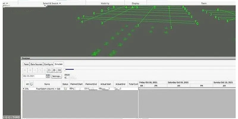
Usage of Navigation tool , Timeliner and Clash Detection test using Naviswork
1) Use the Architecture/ Structure Project file developed by you in Week 6 to 8. Export the Revit architecture and structure model to Navisworks Cache file following the export settings discussed in class
AIM:
To use the Architecture/ Structure Project file developed in Week 6 to 8. Export the Revit architecture and structure model to Navisworks Cache file following the export settings
INTRODUCTION:
Navisworks (known for a while as JetStream) is a 3D design review package. Its used primarily in construction industries to complement 3D design packages (such as Autodesk Revit, AutoCAD, and MicroStation), Navisworks allows users to open and combine 3D models; navigate around them in real-time (without the WASD possibility); and review the model using a set of tools including comments, redlining, viewpoint, and measurements. A selection of plug-ins enhances the package adding interference detection, 4D time simulation, photorealistic rendering and PDF-like publishing.
Navistools provides a visual portal to Autodesk Navisworks allowing us to easily link, access and manage complete project data and documentation from a Navisworks model which can then be handed over or shared between project stakeholders throughout the design, construction, management and lifecycle phases. AEC teams use Navisworks Manage for clash detection and advanced coordination, leading to better project outcomes. They use Navisworks Simulate to facilitate smooth 3D model reviews.
We use Navisworks Manage for:
- Coordination and clash detection
- Model review
- Simulation and analysis
- Quantification
- Issues integration with Autodesk Construction Cloud and Revit
PROCEDURE:
STEP 1:
Open week7 project (architectural model)
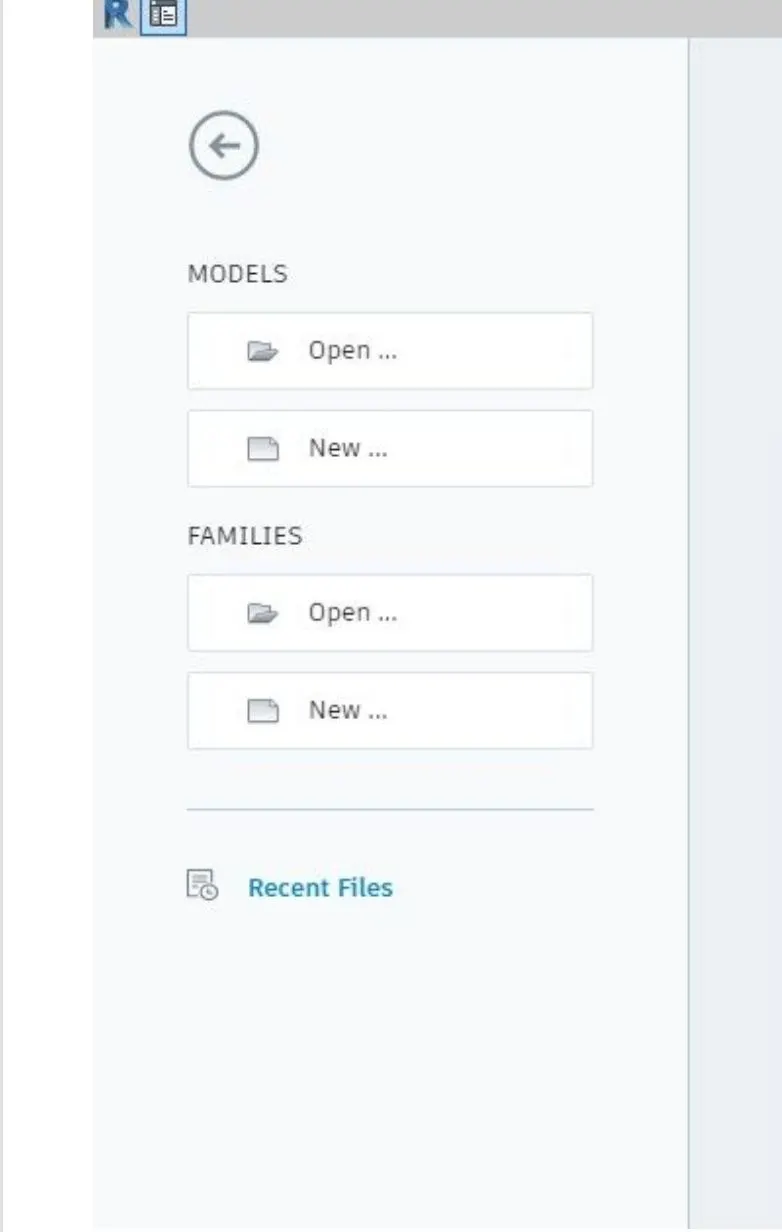
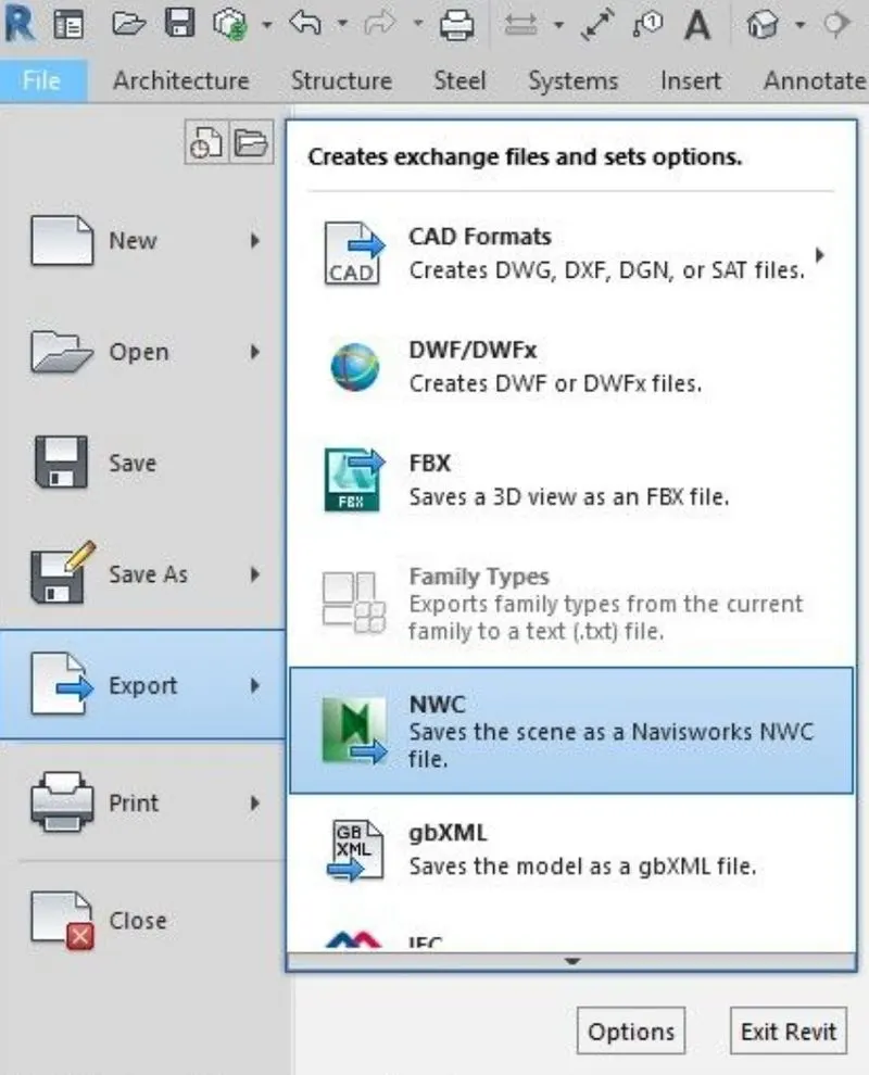
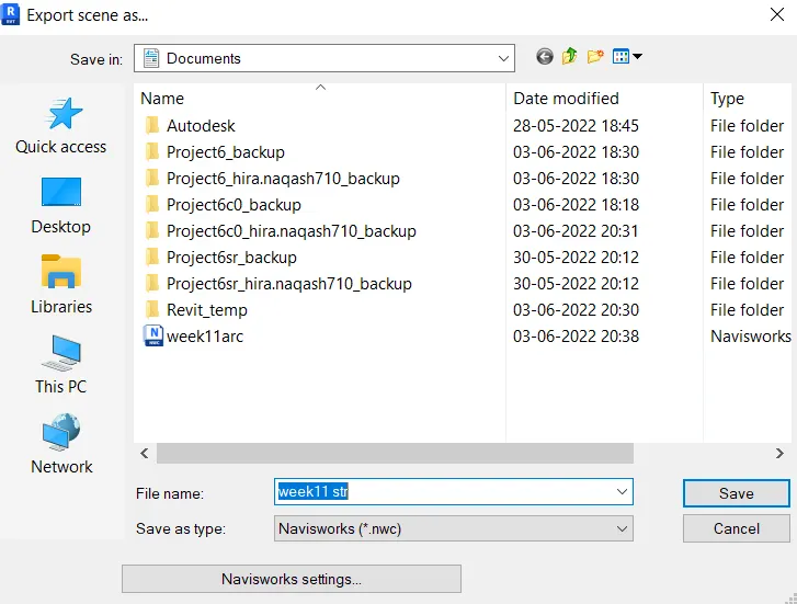
Go to the file, click on export and then select NWC
Save it in a new folder
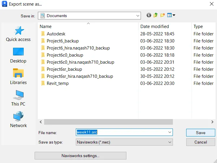
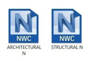
Similarly export structural file
RESULT
Export of Revit architecture and structure model to Navisworks Cache file is done sucessfully using above steps
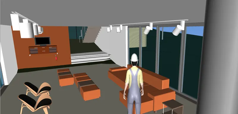
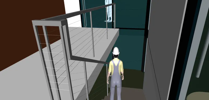
2) Use Navigate Tool to walk around the model and walk through the rooms created and record your moving as animation in your Navisworks file
AIM:
To use Navigate Tool to walk around the model and walk through the rooms created and record your moving as animation in your Navisworks file
INTRODUCTION:
The navigation bar is a user interface element where you can access both unified and product-specific navigation tools.
Unified navigation tools such as Autodesk, ViewCube, 3Dconnexion, and SteeringWheels are those that can be found across many Autodesk products. Product-specific navigation tools are unique to a product. The navigation bar floats over and along one of the sides of the Scene View.
You start navigation tools by clicking one of the buttons on the navigation bar or selecting one of the tools from a list that is displayed when you click the smaller portion of a split button.
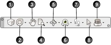
1. ViewCube : Indicates the current orientation of a model, and is used to reorient the current view of a model. Clicking this button displays the ViewCube in the Scene View when it’s not visible.
2. SteeringWheels : Collection of wheels that offer rapid switching between specialized navigation tools.
3. Pan tool: Activates the pan tool and moves the view parallel to the screen.
4. Zoom tools :Set of navigation tools for increasing or decreasing the magnification of the current view of the model.
5. Orbit tools: Set of navigation tools for rotating the model around a pivot point while the view remains fixed.
6. Look tools: Set of navigation tools for rotating the current view vertically and horizontally.
7. Walk and Fly tools :Set of navigation tools for moving around the model and controlling realism settings.
8. Select tool: Geometry selection tool. You cannot navigate through your model during geometry selection.
9. 3Dconnexion: Set of navigation tools used to reorient the current view of a model with a 3Dconnexion 3D mouse.
PROCEDURE:
Open Navisworks manage
Click on file and then select open
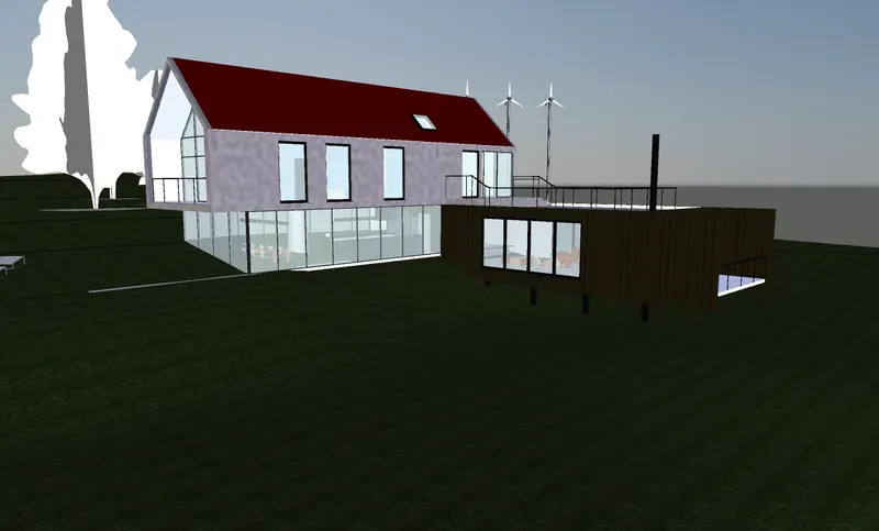
Open architectural file which is saved as NWC format
STEP 2:
Go to view point tab
Click on WALK
Use arrows in the keyboard as left arrow for moving left, right arrow for moving right , top arrow for moving forward and bottom arrow for moving backward
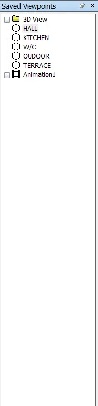
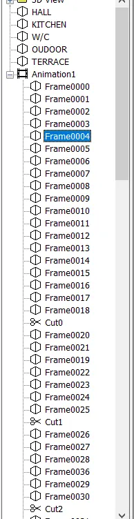
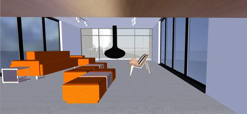
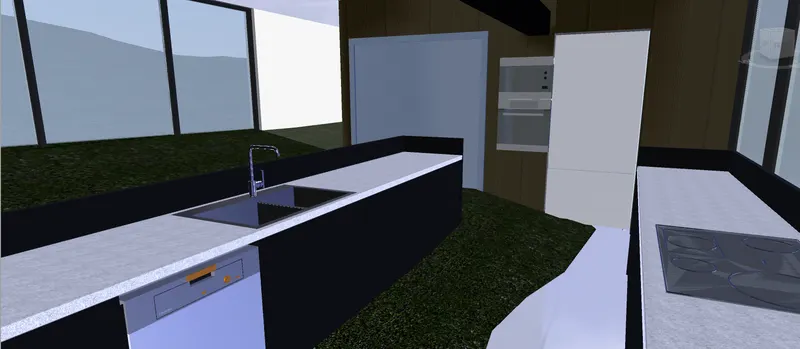
Click on "save viewpoints" and save various views

Click on "record" in save view point and walk around the building
Click on stop and animation is created with various frames select the animation and click on play button in view in view point

Animation created will be played
RESULTS:
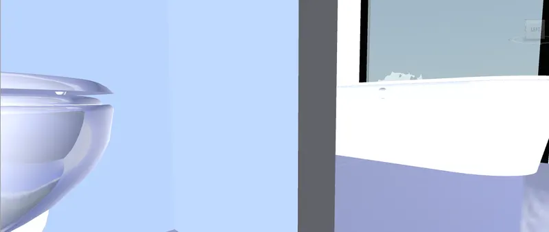
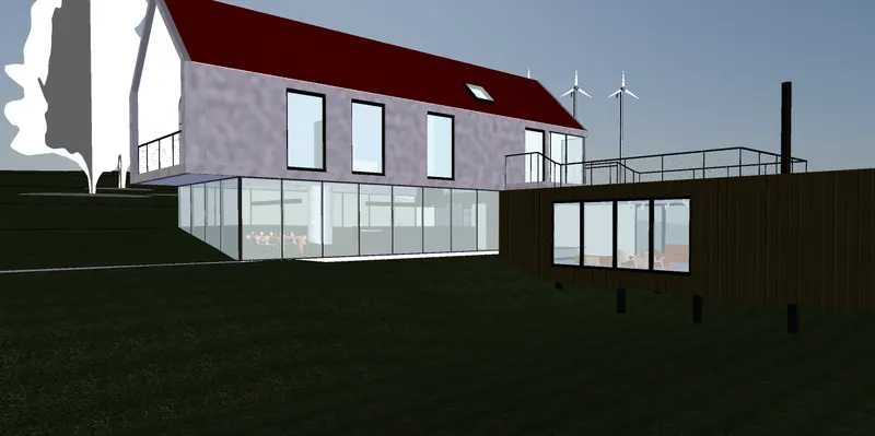
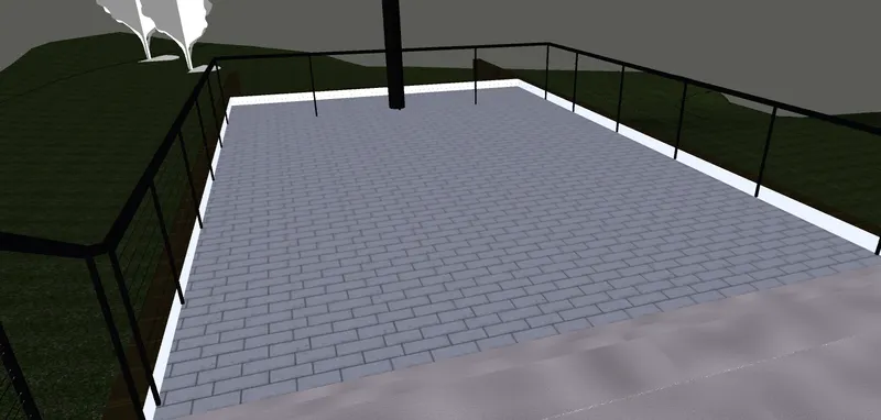
3) Use Navigate tool to use Realism feature to walk through the model and record your moving as animation in Navisworks file
AIM:
To use Navigate tool to use Realism feature to walk through the model and record your moving as animation in Navisworks file
INTRODUCTION:
Realistic views in Revit is a feature that enables a much more creative and easy way of visually communicating your design intent to stakeholders and collaborators.You can easily navigate through your BIM model natively in Revit and display your applied materials in real-time, without having to export outside of the environment.When we navigate a 3D model, you can use the realism tools on the Viewpoint tab > Navigate panel to control the speed and realism of your navigation. The realism tools are not available in a 2D workspace.To enable Realistic View, you go down to the bottom left menu and select Realistic. Changing between the visual styles is straightforward, but to get a good visual from the realistic view, you have to apply the right materials and configure them so they fit with the surfaces they apply to. If there's no material applied, you will end up with a grey surface. Elements such as floors, walls, roofs and ceilings, are defined with several layers in Revit. There's an exterior side and an interior side.One of the tools you have for achieving a really good realistic view is setting the right lighting. Once you have placed your lighting fixtures throughout the project, you can easily modify them in the Edit Type dialogue. Make sure to have the right initial intensity set for your lighting, to make sure that it fits with the right setting you want. The light loss factors are all set to one by default, but changing them will have some effect on how it is displayed on your view
PROCEDURE:
STEP 1
Go to the viewpoint tab
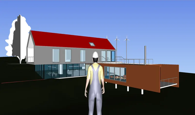
Click on realism tool and select third person
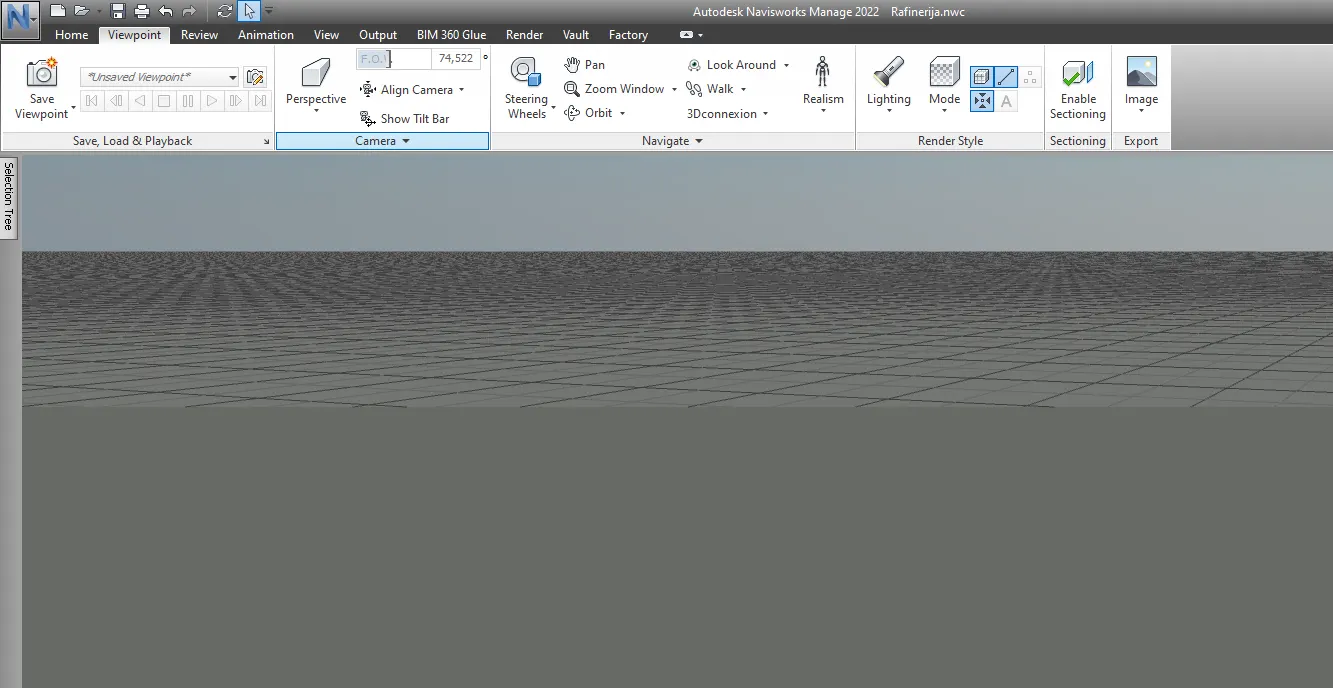
Click on walk and move around the building
Click on record and save the animation
RESULT:
Realism feature to walk through the model is created
a. Run the Clash Detection Test
b. Study the clashes between the two models
c. List which of the clashes could be approved
d. List which of the clashes could be neglected ( will be taken care later)
e. List which of the clashes can be resolved
f. Save the results after color coding the clashes to the Navisworks file
g. In case of resolution annotate the clash and save the view to defined views in Navisworks
- Clash Detection: It allows us to identify, prevent, and resolve conflicts in the virtual model before the actual start of the construction, and hence it reduces costs and schedule risks and minimizes proposed change order and RFI.
- 4D simulation: Autodesk Navisworks Manage allows simulation, coordination analysis, and manage changes that occur during ongoing construction by combining spatial coordination with construction planning.
PROCEDURE:
Open architectural model in navisworks
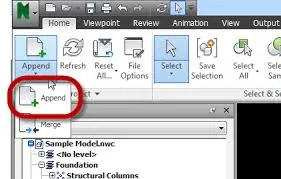
Click on append in home tab
Now click on clash detective in home tab
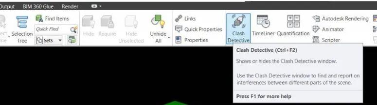
Clip on top arrow and select "Add test"
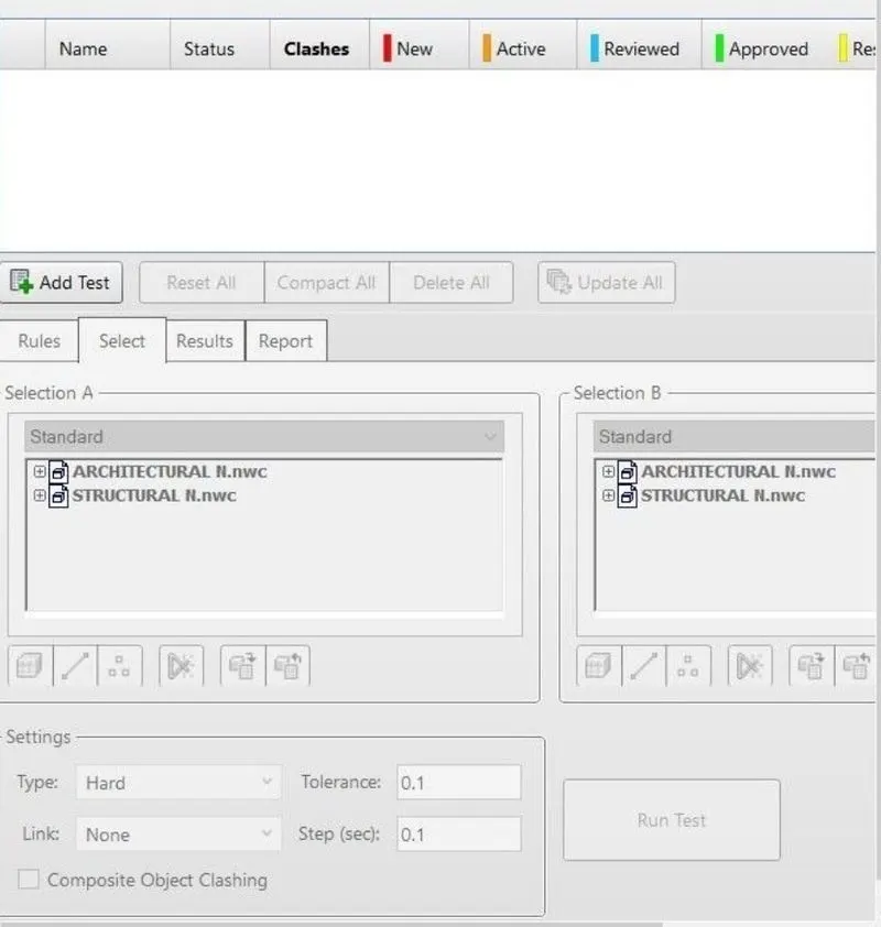
Name the test as "Archi vs Struct"
Select selection A and selection B
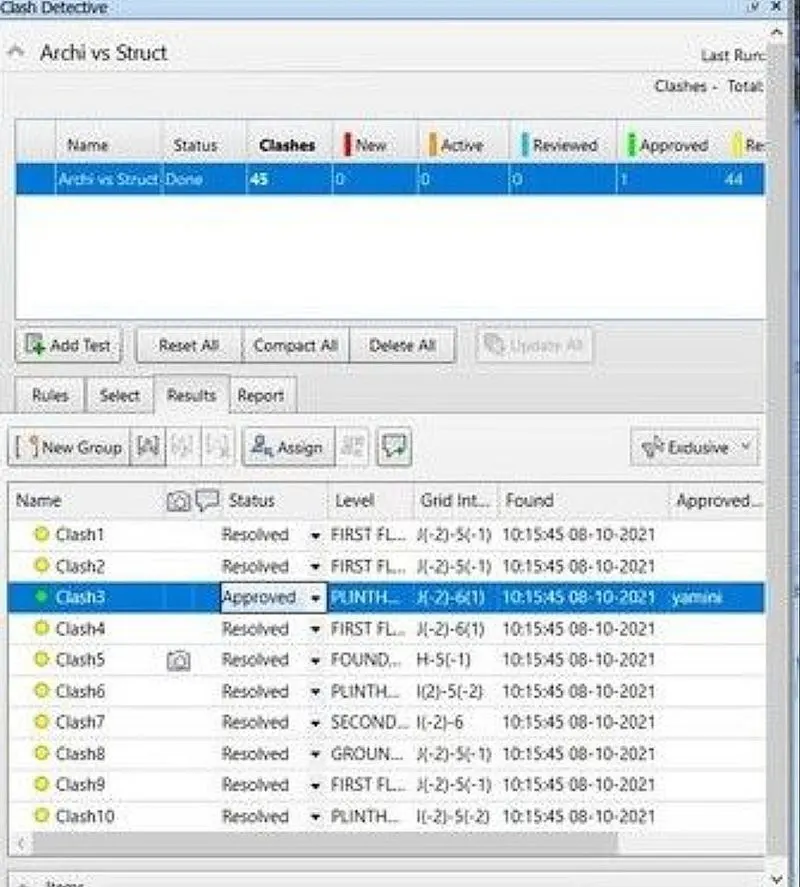
Now select surfaces and click on run test
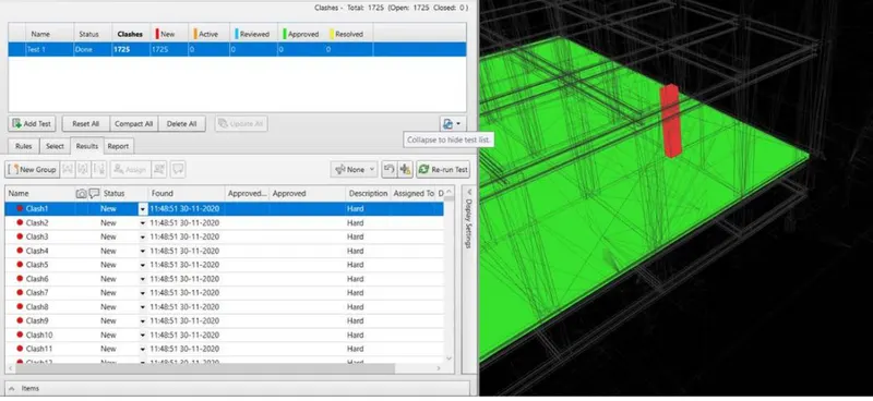
Click on status and change the status to resolved or reviewed or approved accordingly
RESULT:
Total clashes are found accordingly
Approved lists
Remaining lists are resolved
5) Using the Timeliner feature in Navisworks prepare a schedule for the project developed in week 6 to 8 by adding reasonable assumptions for task start date and end date and simulate the task completion as a visual simulation. Record it and save the timeline simulation to Navisworks file
AIM:
To use the Timeliner feature in Navisworks prepare a schedule for the project developed in week 6 to 8 by adding reasonable assumptions for task start date and end date and simulate the task completion as a visual simulation. Record it and save the timeline simulation to Navisworks file
INTRODUCTION:
The TimeLiner tool adds schedule simulation to Autodesk Navisworks. TimeLiner imports schedules from a variety of sources. You can then connect tasks in the schedule with objects in the model to create a simulation. This allows you to see the effects of the schedule on the model, and compare planned dates against actual dates. Costs can also be assigned to tasks to track the cost of a project throughout its schedule. TimeLiner also allows the export of images and animations based on the results of the simulation. TimeLiner will automatically update the simulation if the model or schedule changes.
We can combine the functionality of TimeLiner with other Autodesk Navisworks tools:
- Linking TimeLiner and Object Animation together enables the triggering and scheduling of object movement based on start time and duration of project tasks, and can help you with workspace and process planning. For example, a TimeLiner sequence may indicate that when a particular site crane moves from its start point to its end point over the course of a particular afternoon, a workgroup working nearby causes an obstruction along its route. This potential obstruction problem can be resolved before going to site (e.g., the crane can be moved along a different route, the workgroup moved out of the way, or the project schedule altered).
- Linking TimeLiner and Clash Detective together enables the time-based clash checks on the project.
- Linking TimeLiner, Object Animation, and Clash Detective together enables clash testing of fully animated TimeLiner schedules. So, instead of visually inspecting a TimeLiner sequence to make sure, for example, that the moving crane didn't collide with a workgroup, you can run a clash test.
Note: This feature is available for Autodesk Navisworks Manage users only.
In Autodesk Navisworks, the process of creating and running TimeLiner simulations is as follows:
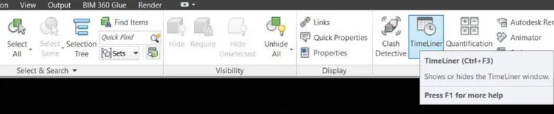
- Load a model into Autodesk Navisworks in the usual way and then click Home tab >Tools panel >TimeLiner. Although the ability to create simulations is limited to users with access to the full TimeLiner functionality, Navisworks Freedom can play back simulations once they have been set up.
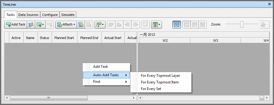
- Create some tasks, each having a name, start and end date and a task type. We can add tasks manually. Alternatively, click Auto-Add Tasks on the Tasks tab, or right-click within the Tasks area, and create an initial set of tasks based on layer, item, or selection set names. TimeLiner defines some default task types for you (Construct, Demolish and Temporary), or you can define your own task types on the Configure Tab. You can also view a read-only graphical representation of your project schedule, and can switch between Planned, Actual, and Planned vs Actual Gantt charts.
PROCEDURE:
Go to home tab
Click on timeliner
Click on "selection tree" in home tab
Click on add task in "Timeliner"
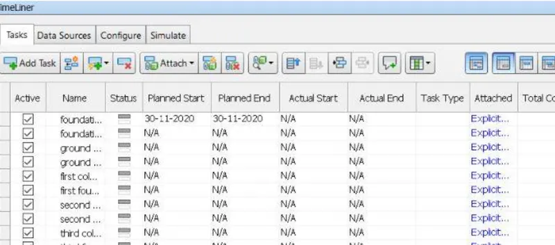
Task 1- Foundation columns + slab
Task 2- Plinth level
Task 3- Level 1
Task 4- Level 2
Task 5- Level 3
Enter dates and types as shown below
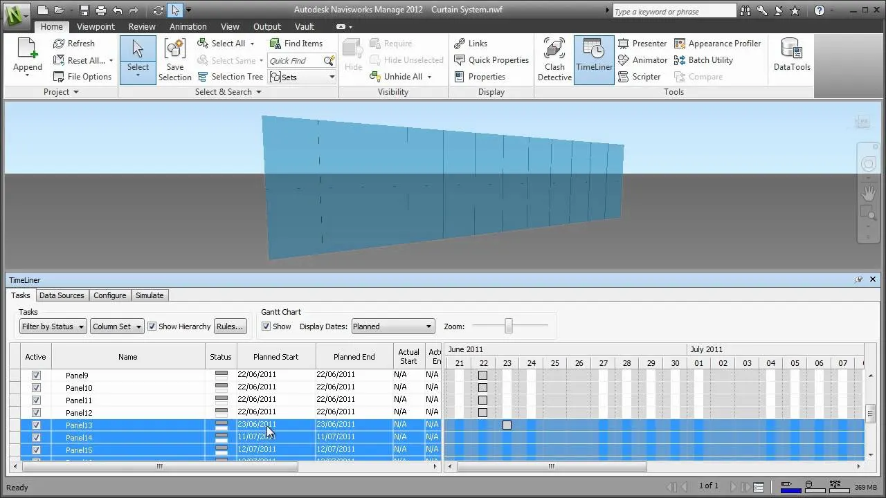
Now click on simulate and click on record at save view point
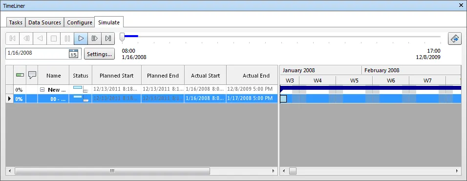
RESULT:
Timeline simulation to Navisworks file is recorded and saved