Usage of Collaborate tool in REVIT
1) Open an architectural template. Using the Manage tab set project base point and project shared coordinates for the project.
Answer - Introduction - The project base point can be used to establish a reference for measuring distance and positioning
objects in relation to the model.
Initially , in stock templates . it identifies the origin (0,0,0) of the project co ordinate system. Use the project base point as a
referance point for measurement across the site.
When you combine multiple models and files in a sinle project , use shared cordinates to establish the position of the files in
relation to each other.
A Revit project has internal coordinates for all the elements that compose the model in a project. Those co ordinate are known
to this projet only.
This is sufficient if you have a standlone model whose position is not relevant to other models or to a site.
However, if you want the position of the model to be known to other linked model , you need shared coordinates.
Use the shared coordinates tools to establish the relative position of the diffrenet files and ensure that those relationship are maintained.
To establish a common cordinate position and then share that position between files ,use the aquire co ordinates tools or the publish coordinates tools.
Procedure -
First we have open to Revit.
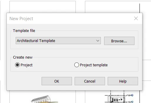
Next create project using the architectural Template.
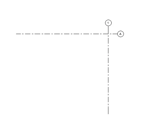
Next draw the horizontal and vertical grid , intersectibg each other.
And give name for horizontal grid as A.
Next give the name for vertical grid as 1.
Next we coordinates option in manage tab , and select the specify the coordinates at point option and click on the horizontal
grid.
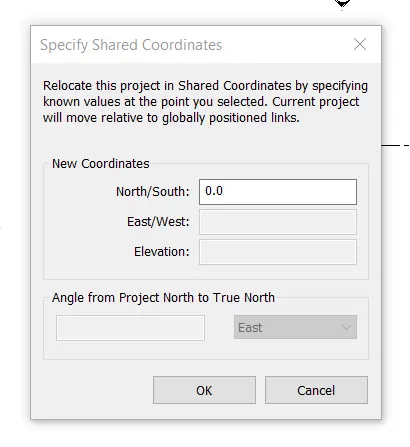
After Selecting the horizontal grid ,the specify shared coordinates will ve appears.
In the specify shared coordinates tab we need to enter the coordinate for north/south as 0'0".
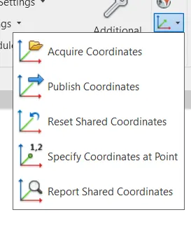
Next we coordinates option in manage tab , and select the specify the coordinates at point option and click on the vertical
grid.
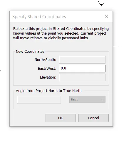
After Selecting the vertical grid ,the specify shared coordinates will ve appears.
In the specify shared coordinates tab we need to enter the coordinate for east/west as 0'0".
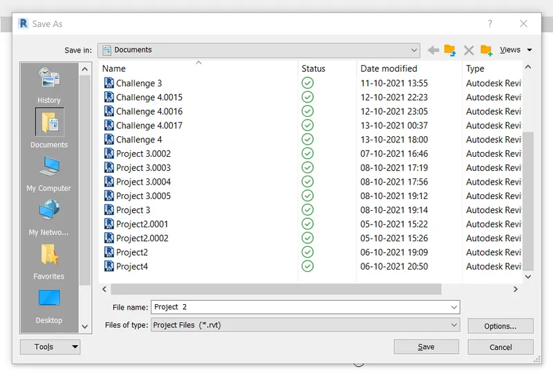
Next we save the project as Project 2.
Result - Using the manage tab the project base point and project shared coordinates have been steup successfully for the
project in the architectural Template.
2) Open another new file but with a structural template. Using the manage tab set project parameters the same as the architectural model. Copy the parameters from the architectural model to the structural template or enter the parameters manually into the structural model.
Introduction -
The project base point can be used to establish a reference for measuring distance and positioning
objects in relation to the model.
Initially , in stock templates . it identifies the origin (0,0,0) of the project co ordinate system. Use the project base point as a
referance point for measurement across the site.
When you combine multiple models and files in a sinle project , use shared cordinates to establish the position of the files in
relation to each other.
A Revit project has internal coordinates for all the elements that compose the model in a project. Those co ordinate are known
to this projet only.
This is sufficient if you have a standlone model whose position is not relevant to other models or to a site.
However, if you want the position of the model to be known to other linked model , you need shared coordinates.
Use the shared coordinates tools to establish the relative position of the diffrenet files and ensure that those relationship are maintained.
To establish a common cordinate position and then share that position between files ,use the aquire co ordinates tools or the publish coordinates tools.
Procedure -
First we have open to Revit.
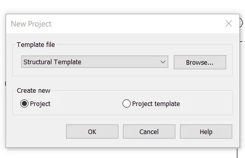
Next create project using the Structural Template.
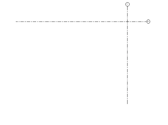
Next draw the horizontal and vertical grid , intersectibg each other.
And give name for horizontal grid as A.
Next give the name for vertical grid as 1.
Next we coordinates option in manage tab , and select the specify the coordinates at point option and click on the horizontal
grid.
After Selecting the horizontal grid ,the specify shared coordinates will ve appears.
In the specify shared coordinates tab we need to enter the coordinate for north/south as 0'0".
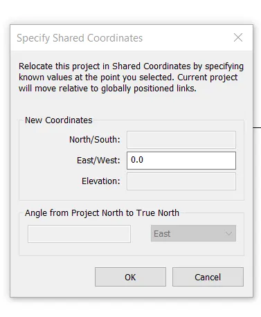
Next we coordinates option in manage tab , and select the specify the coordinates at point option and click on the vertical
grid.
After Selecting the vertical grid ,the specify shared coordinates will ve appears.
In the specify shared coordinates tab we need to enter the coordinate for east/west as 0'0".
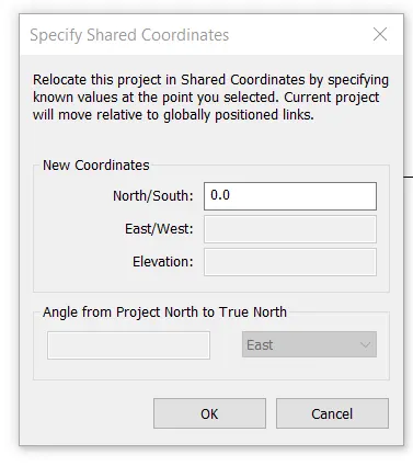
Next we save the project as Project 3 structural.
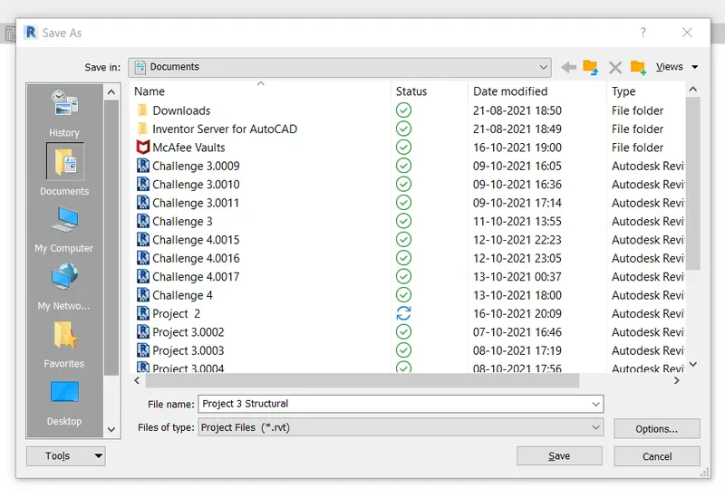
Result - Using the manage tab the project base point and project shared coordinates have been steup successfully for the
project in the Structural Template.
3) Re-open the architectural model. Using the tools under the Collaborate tab make the architectural model a central model (enabling simultaneous working on the model).
Introduction -
With server based worksharing, some of the tasks to manage central model require a different approach than file based
worksharing.
The central model is the master project file for a workshared project.
The central model stores the current owenership information for all elements in the projects , and act as the distribution
point for all changes published to the file.
All team members save their own local copies of the central model ,worl locally , and then use the synchronize with central
command to synchornize their edits to the model with central model.
Procedure -
First we open the Revit and draw the horizontal and Vertical grids.
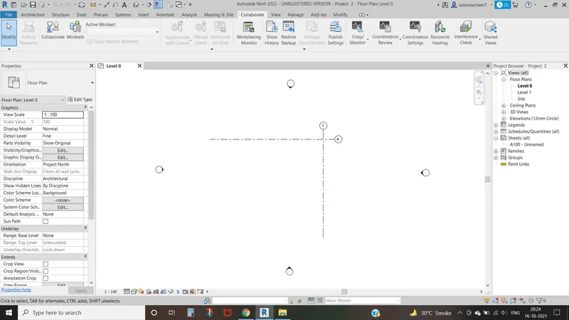
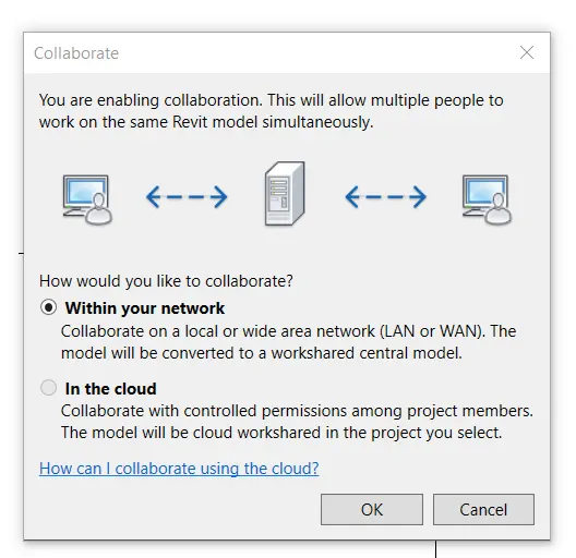
Next click on the collaborate tab ,then the new tab will be visible.
Then click on the ok button.
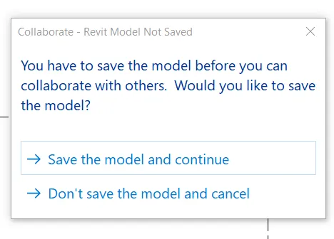
Next we see another tab , and select save model and continue option.
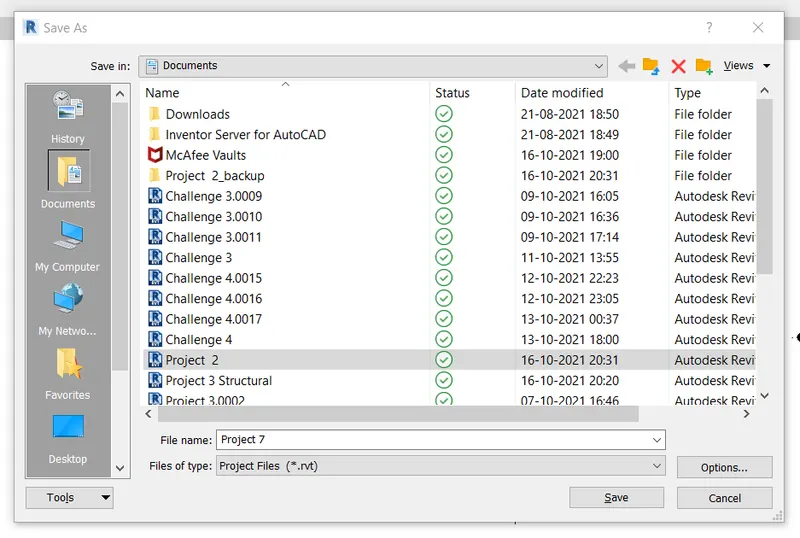
Next we save the project as Project 7.
Next we save the project file as Central Model.
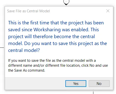
Result - Created an Architectural model as acentral model using the collaborate tab.
4) Create the Grids Longitudinal and Transverse pattern for the project similar to the task done in Week 2.
Introduction -
Grid lines are finite planes. We can drag their extents in elevation views that they do not intersect level lines.
This allows you to determine whether grid lines appear in apear in each new plan view that you create for a project.
Grids can be straight lines ,arcs or multi segmented. You can hide grid lines after you add them.
We can then add columns along the column grid lines.
Procedure -
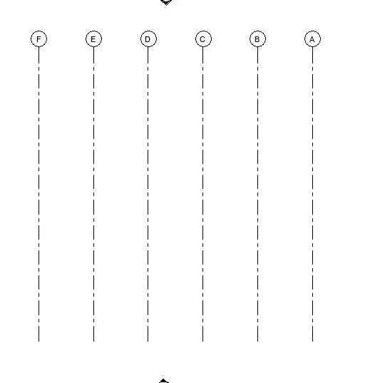
First we create vertical grid lines.
Next we create horizontal grid lines.
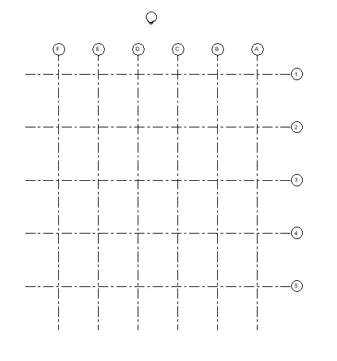
The vertical and horizontal grids are created successfully.
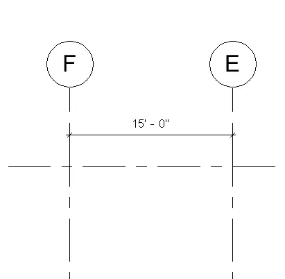
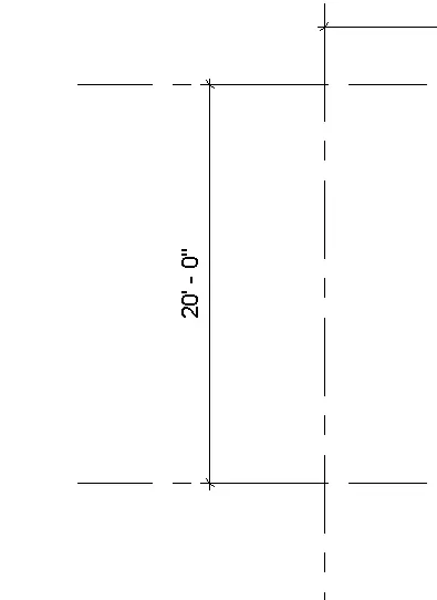
Result - Created the grids Longitudinal and transverse pattern for the project similar to the task done in week 2.
5) Synchronize the changes from the local copy to the central file of the architectural model.
Introduction -
The Synchronize with central process loads changes from other files to the central file, and then save local changes to central
file which are saved by default.
The central file access pane of worksharing monitor displays the progress of the synchronize with central operation, which involves several distinct steps.
Procedure -
First we have collaborate using the collaborate toolbar.
Next we have to save the project as central model.
Next the synchronize option will be visible.
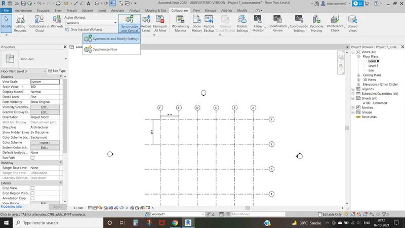
After selecting the synchronize option , a new tab will be appears and click ok.
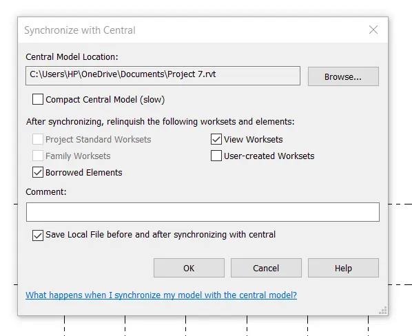
Result - Synchronized the changes from the local copy to the cental file of the architectural Model.
6) Open the structural model and use the collaborate tools to save the model as a central file.
Introduction -
With server based worksharing, some of the tasks to manage central model require a different approach than file based
worksharing.
The central model is the master project file for a workshared project.
The central model stores the current owenership information for all elements in the projects , and act as the distribution
point for all changes published to the file.
All team members save their own local copies of the central model ,worl locally , and then use the synchronize with central
command to synchornize their edits to the model with central model.
Procedure -
First select structural template , then the new project will be opened.
Next click on the collaborate tab , then the new tab will be visible.
Then click on the OK button.
Next we save the project file as acentreal model.
Result - Saved the model as a central file using the collaborate tool in the structural model.
7) Under the Collaborate tab, select the grids and levels from the architectural model, and using Copy Monitor try to copy the grids to the structural model. See what happens when the copy monitored grid is moved around in the structural model.
Introduction -
When you start the Copy / Monitor Tool , you can select use current project or select link.
Then you can select copy or monitor.
Procedure -
First we have create longitudinal and transaverse grids.
Next we select the copy /monitor tool , and click on the selct link option.
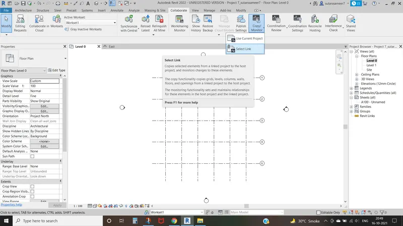
After selecting the copy / monitor option , then selct the copy option and select the grids which you want to copy , and press
enter.
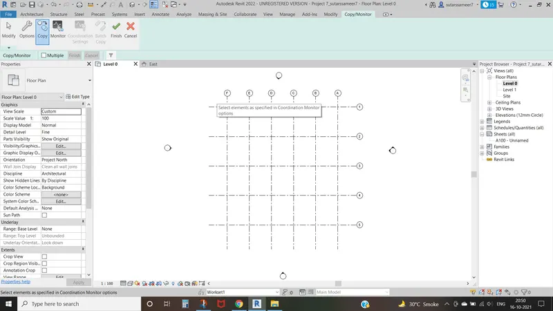
Copied the grids from architectural model to structural model using the copy /monitor tool.
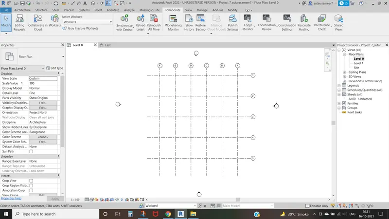
Result -
Successfully copied the grids from architectural model to structural model using the copy /monitor tool.
8) Create another new file with a construction template. Save the new file as a central model. This file will include both architectural and structural model. Under the manage tab, Click manage links to link both architectural and structural files. Save the file and close all the files.
Introduction -
To manage the link in the model,selct the manage link in the dialogue and use the appropriate tool.
You can selct the multiple links modify by pressing ctrl and clicking on the number on link in the dialogue.
Procedure -
First open a new project using a construction template.
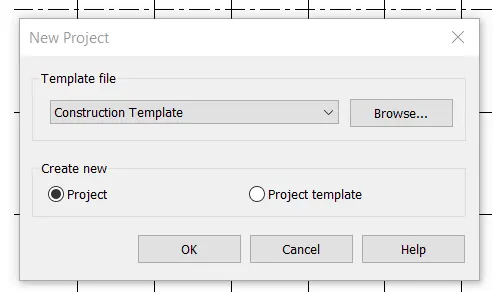
Next the project tab will be opened.
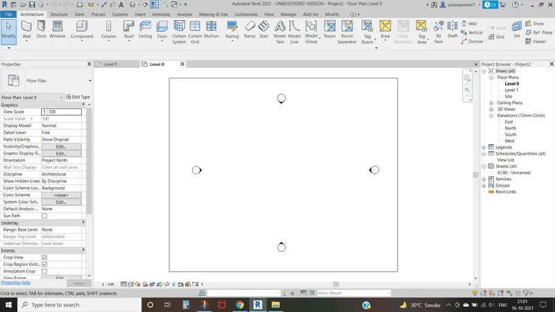
Next select the collaborate toolbar.
and next click on the collaborate option.
Next the new tab will be visible.
then click on the OK button.
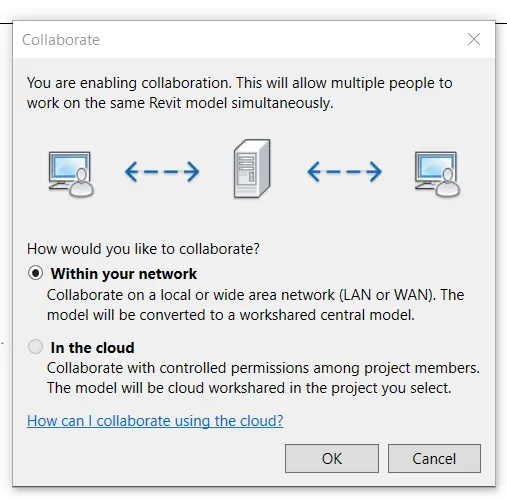
Next we save the project file as a central model.
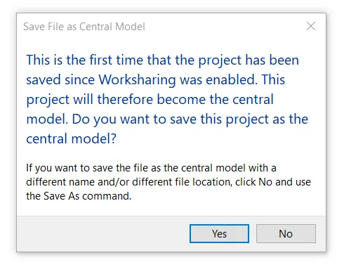
Next the synchronize option will be visible.
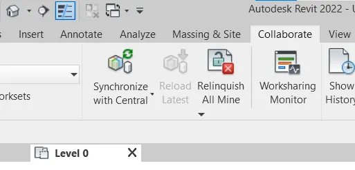
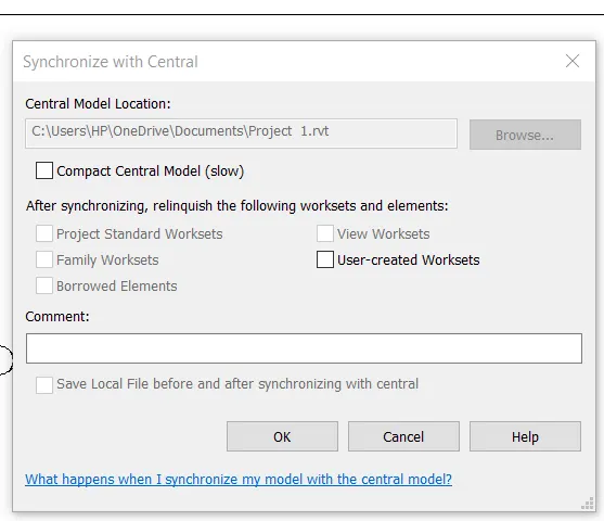
After selecting the synchronize option a new tab will be appears and click ok.
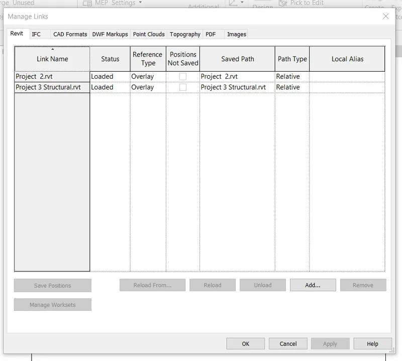
Next we click the manage links and link the architectural nd structural model.
After clicking the ok button on the manage links,then the grids will be resulted.
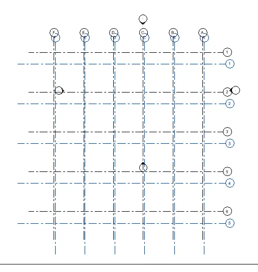
Next we click the aquire coordinates and select the model and press enter.
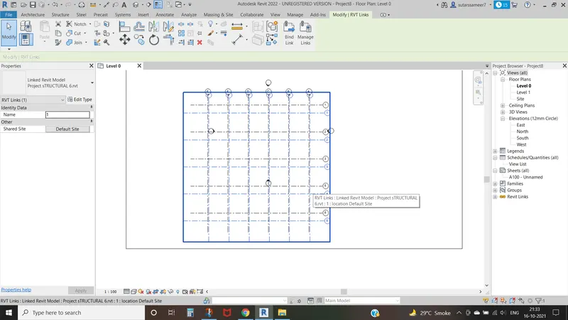
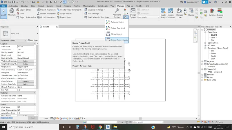
Next we click on the relocate project option, and selct the points of both architectiral and structural model visible on the scree.
The both structural and archirectural model are link.
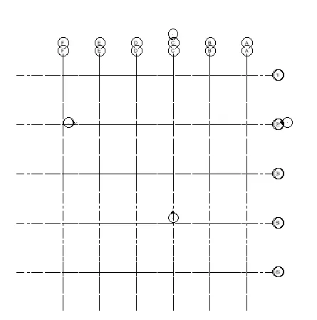
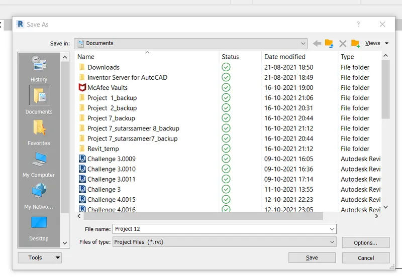
Next we save the project as Project 12 and close the all files.
Result -
Created new file with construction template and saved the new file as central model.
An both architectural and structural files are linked successfully in a single project using the manage links tool.
9) Are the grids from structural and architectural model matching in the construction template created? If yes the model is set up for project 2. If not work on the shared parameters and linking options under Manage links
( Hint: origin to origin, by shared coordinates or by project base point to base point ) to link the models in an appropriate manner.
Answer -
Yes , the grid from structural and architectuural model matching the construction template created successfully and my model is set up for project 2.
10) List a flow chart of a project tree set up in terms of Construction model, Architecture & Structure model, in this exercise and understand how many people can work on the same project using Revit simultaneously.
Answer -
For the construction model the project tree is as -
Site access
Logistic and storage
quality control
Outstanding contract details
Health and safety.
For Architectural Model -
Creating Doors
Creating Windows
Creating walls
Creating Staircase
Assigning Materials
For Structural Model -
Creating Foundation
Creating Beams
Creating Columns
Create Floors
Create Cieling