Creating a Floor plan, Footing detail and Isometric view using AutoCad
Drawn the fifth rectangle command REC
Specify the corner point as the corner of fourth rectangle
Erase the unwanted line by trim
Result - The cross section of load bearing wall over spread footing is drawn
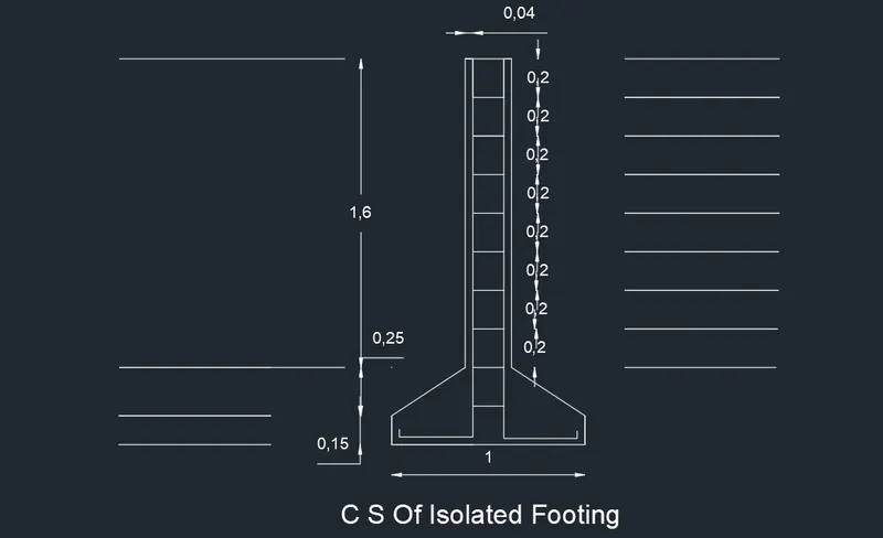
Aim - To draw C/S of Isolated footing
Commands Used - Line ,Offset and trim
Procedure - Draw line with command and give 1 units
Give command L and give relative coordinates as 0,0.15.
Give next coordinates 0.38 and 0.25
Next coordinates is given as 0,1.6
Give 0.28,0 and next cordinates as 0,-1.6 also 0.38,-0.25 also 0,0.15 and close.
Give command O and select the object and give the distance 0.04
Do the same right and left bottom and trim the unwanted lines.
Give the command O and select the object and give the distance 0.20 -Select multiple option 9 such a line and trim unwanted lines
Result - C/S of isolated footing is drawn.
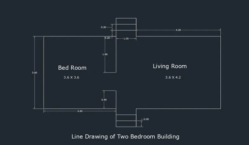
Aim - To draw a line diagram of 2 bedroom building.
Commands Used - Line , offset ,trim and rectangle
Procedure - Creating a bedroom room by rectangle (8.2 x 3.6)
Give the command O and specify the distance of 3.6 units from left bottom end also give the coomand O and specify the distance 4.2 units from the right bottom end.
Draw an offset at a distance of 0.3 between the two line to the bottom side. Repeat the the same step and create two offset.
Do the same procedure on top and trim the unwanted lines.
Using the line commands and draw a line at a distance of 3.2 units from the left bottom end up to 0.9 units also draw a line at a distance of 3.2 units from the left top end up to downwards to 1.8 units .
Result - Line Diagram of 2 Bedroom Building is Drawn.
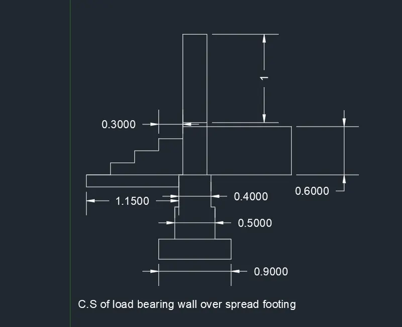
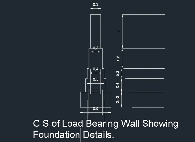
Aim - To draw the C/S bearing wall showing foundation details.
Commands Used - Line ,Rectangle and trim
Procedure - Create a rectangle by typing REC in command box give the length 0.9 and width 0.45 in command box.
Specify the first corner point which 0.15 from the starting point of first rectangle .Create a another rectangle and give the length and width 0.6 and 0.4 in command box
Specify the first corner point which 0.05 from the starting point of first rectangle .Create a another rectangle and give the length and width 0.5 and 0.3 in command box
Specify the first corner point which 0.05 from the starting point of first rectangle .Create a another rectangle and give the length and width 0.4 and 0.6 in command box
Specify the corner point as the corner of fourth rectangle. Click on the dimension give length as 0.3 Units and width as 1 units and trim the unwanted lines.
Result - The C/S of bearing wall showing foundation details is drawn.
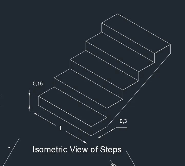
Aim - To draw a Isometric View of Steps
Commands - Line and Isometric plane
Procedure - From isometric drafting select Iso plane left .Give command L and give 1 unit. Moving the cursor Y direction and give 0.15 units. Moving the cursor x direction and give 1 unit and cursor y direction give 0.15 unit.
Change the isometric drafting to Iso plane Top . Move the cursor back and give 0,3 units from the last drawn point . Move the cursor right direction and give 1 unit and cursor move to front and give 0.3 units.
Change the isometric drafting to Iso plane right . Copy the object drawn ,ortho off .Command co and specify the base point and place it new point .repeat it untile 4 steps are formed.
With iso plane right join the two ends with ortho off.
Result - The steps are drawn in Isometric View.
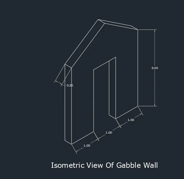
Aim - To draw the isometric view of Goble wall.
Commands Used - Line and Isometric plane
Procedure - To select the isometric drafting to Iso palne left . Give command L and moving the cursor right and give 1 unit .Pointing the curssor upwards give 3 unit .Draw 0.3 units to left and 3 units downwards and 0.3 unit left.
Using Isometric right draw 1 units towards the right and 2,42 units to down wards.Using isometric left again and using line command and draw o.3 uits to the left side .and draw line which is intersects the top line.
Using isometric right and using line command draw 1 units to right side and 3units to upward side.
By using the line command and draw a line from bottom left corner 1.5 units and extend line 4 units upwards.
Draw the vertical line with ortho on 0.3 units and join vertical line using line from left and right end .Remove the unwanted line.
Result - The Isometric view of goble wall is drawn.