MESHING THE INTAKE MANIFOLD OF AN ENGINE USIGN TETRA ELEMENTS IN ANSA v20.1.4
OBJECTIVE:
The main aim of this project is to mesh the Intake manifold of an engine using tetra elements as per the quality criteria shown below.
QUALITY CRITERIA:
|
S.No |
Quality Criteria |
Value |
|
1 |
Target/Average length |
3 |
|
2 |
Minimum Length |
1 |
|
3 |
Maximum Length |
5 |
|
4 |
Tetcolapse |
0.2 |
PROCEDURE:
GEOMETRY CLEAN UP:
- Imported the given .IGS file in the ANSA work page.
- Checked for the orientation i,e. the upper part of the model should be in gray color meaning positive and the lower part in yellow color meaning negative.
- The issues with orientation are cleared using the topo module-->faces-->topo.
- The resolution of the CONS is improved using Auxiliaries--> fine from topo module or perimeters-->length from mesh module.
- The model is then subjected to a geometry checkup to check any free edges between the models, duplicate surface, irrelevant CONS using the option tools--> checks-->geometry.
- Some geometrical errors are cleared using the Auto fix option and some are manually done using options like release hot points, release cons, topo, faces cut, etc. from the Topo module.
- Normally, it is recommended to use 3D meshing for the casting components and also for the components that exceed the thickness of 5 mm.
- The surfaces are splitted using the faces-->cut, macros-->cut options according to the Quality criteria in order to avoid element failures during meshing.
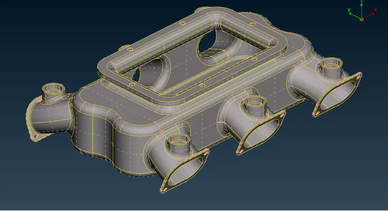
1.Model With Surface Split
MESH GENERATION:
- The surface of the solid model has meshed with tria elements and then it is converted into 3D elements.
- The Quality criteria are applied to the model using utilities--> Quality criteria as shown below,
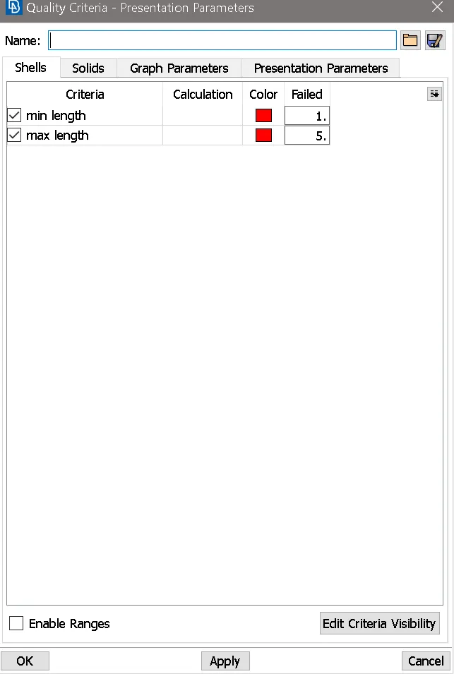
2.Quality Criteria For Tria Elements
- Mesh parameters are applied as shown below, using utilities--> mesh parameter.
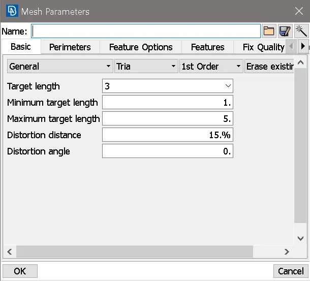
3.Quality Parameter
- The perimeter elemental length of 3 mm is applied to the model using the mesh module --> perimeter--> length option.
- The split surfaces are meshed one by one using mesh module--> mesh generation--> Best and spot mesh option.
- Normal trias and ortho trias elements are used while meshing the surfaces.
- The curved surfaces and fillet regions have meshed with ortho tria elements for better feature capturing and Normal tria elements are used in the plane surfaces.
- The ortho tria elements alone can be used to mesh the model but the number of elements increases, so the computation time increases.
- During meshing the irregular mesh flow can be removed using shell mesh--> reconstruct option.
- The elements which fail for quality can be viewed by using the Draw mode toolbar --> hidden option and corrections are done for the elements which fail for quality.
- The smooth-->shell mesh option is used to attain good mesh flow.
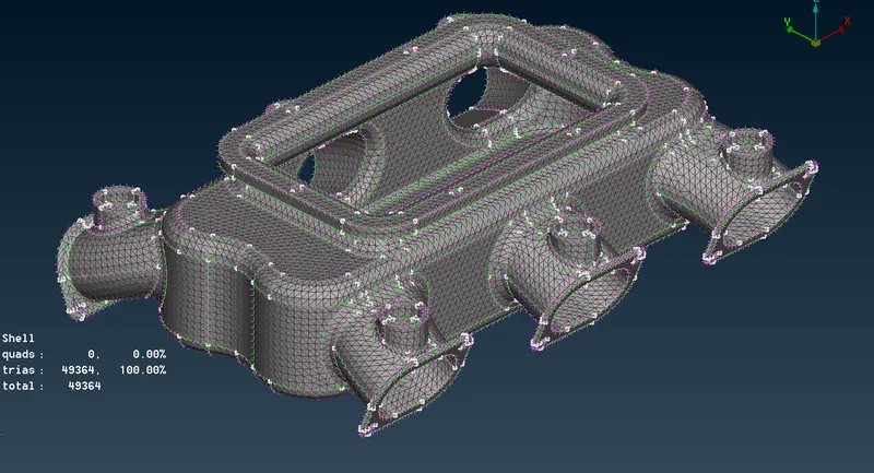
4.Meshed Model
- After the shell mesh and checking for quality criteria, ensuring that the model is fully closed, it can be taken to generate tetra elements.
Tetra elements generation:
- The generation of solid elements can be done with the volume mesh deck.
- The model is defined as a volume with Volume mesh--> volumes -->Define option, so that ANSA considers the model as a volume to generate solid elements.
- The model has four volumes are defined as shown below, this can be viewed with the volumes-->list option.
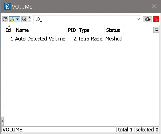
5.Volume Defined
- The solid elements are generated using the unstructured-->mesh--> Tetra rapid or Tetra FEM option.
- Difference between Tetra rapid and Tetra FEM option:
- Tetra rapid option meshes the volume with Tetra elements.
- Tetra FEM option creates a Tetrahedral mesh inside selected Volumes, initially with pyramid elements if the starting surface mesh contains quad elements. It is to be used mainly for structural applications.
- In Tetra FEM, the generation of tetra elements is greater than with the tetra rapid option. so, the computation time increases with the Tetra FEM option.
- After the generation of the solid elements, the quality parameter Tetcollapse is checked for mesh quality.
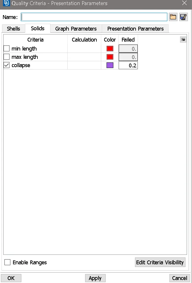
6.Quality Parameter for Tetra elements
- The elements which fail for Tetcollapse can be resolved using improve-->fix quality option unless there are dents or peaks formation.
- Tetcollapse can be manually resolved using mesh-->grides-->move free option.
- Once it is completed, the solid model can be viewed using the Visibility toolbar --> volume option.
- Finally, saved the model.
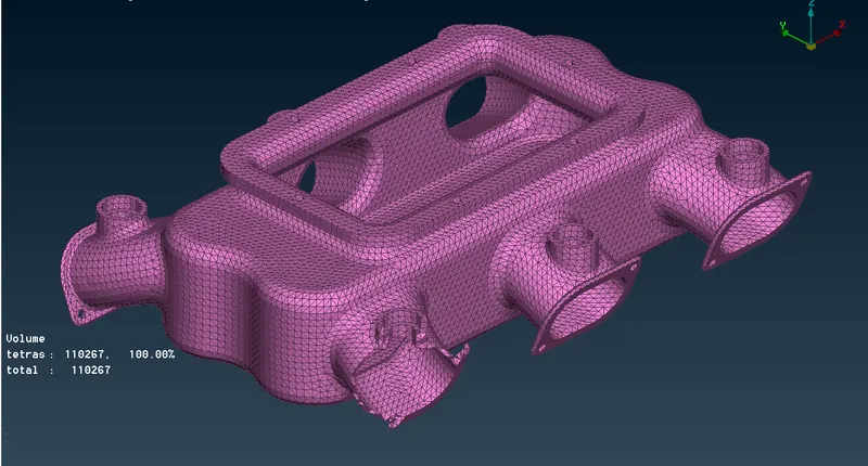
7.Solid Model
RESULT:
Hence, the Intake manifold of an engine model has meshed with 3D tetra elements as per the given Quality criteria.
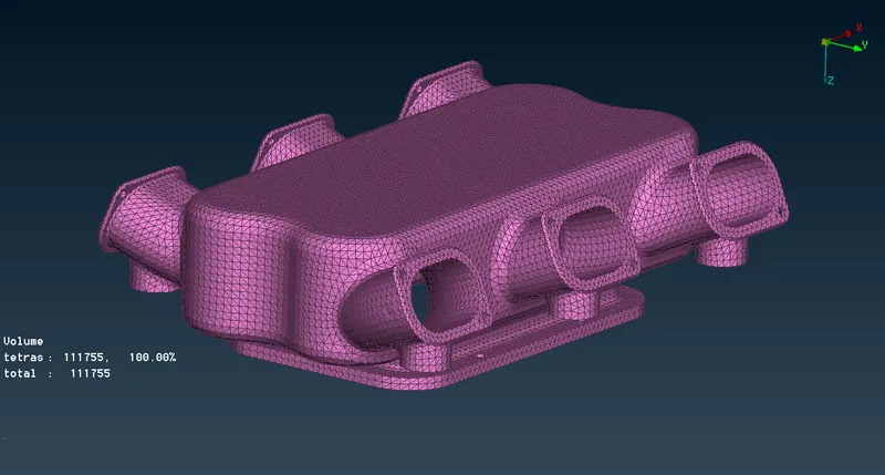
8.Full Model
LINK TO VIEW THE MODEL: