TO SIMULATE AND COMPARING THE BENDING IN BEAMS BY USING SOLIDWORKS
AIM :
To create a three different cross sectional beam such as rectangular section, I section & C section to run a simulation separately. Comparing the result like stress, strain & displacement for all the cases.
FLOW OF CONTENT/METHODOLOGY :
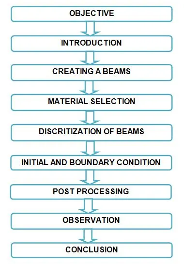
OBJECTIVE :
1) Create a three different cross section beam with appropriate given dimensions.
2) Provide a boundary condition for those all cases with proper manner.
3) Creating a mesh and run a simulation for all the cases separately.
4) Extracting a useful datas from numerical model.
INTRODUCTION :
Finite element analysis :
A finite element analysis is the process of simulating the behaviour of a part or assembly under given conditions so that it can be assessed using the finite element method (FEM). FEA is used by engineers to help simulate physical phenomena and thereby reduce the need for physical prototypes, while alllowing for the optimisation of components as part of the design process of a project.
Finite element analysis works :
The simulation used in FEA are created using a mesh of millions of smaller elements that combine to create the shape of the structure that is being assessed. Each of these small elements is subjected to calculations, with these mesh refinement combining to produce the final result of the whole structure.
These approximate calculations are usually polynomial, with interpolations occuring across the small elements, meaning that values can be determined at some but not all points. The points where the values can be determined are called nodal points and can usually be found at the boundary of the element.
Types of FEA simulation :
i) Vibration and Impact : These are types of dynamic analyses that can be used to assess how a product will perform. For example, will the car steering wheel vibrate while driving ? Would my product survive a drop onto floor from one metre up.
ii) Buckling : A length of wire can hold much less load in compression compared to tension due to a phenomenon called 'buckling'. It can occur in any object that is relatively thin/narrow in one direction, such as beams and sheet metal parts. FEA can be used to predict the load at which an object will partially or fully buckle.
iii) Contact : This non linear technique analyses the effect of parts contacting each other. For example, a car crashing into a flexible safety barrier or a bolted 'friction grip' joint.
iv) Fatigue : Finite element analyses is a powerful tool for assessing the complex effects of cyclic loading (fatigue) on components. A product life can be estimated in years and areas likely to crack highlighted.
v) Heat transfer and Thermal deflections and stresses : FEA can be used to calculate the effect of heat on a components strength and temperature distribution.
vi) Creep and Relaxation : A lot of engineering materials will tend to gradually stretch over time and can eventually rupture in a process called 'creep'. This is a key consideration for most plastic designs and is highly influenced by temperature. FEA can predict this behaviour.
Types of beams :
1) Cantilever beam
2) Simply supported beam
3) Overhanging beam
4) Continous beam
5) Fixed beam
CREATING A BEAMS :
i) Rectangular section :
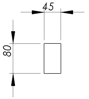
Given Cross section of beam :
Cross section of beam drawn in solidworks :
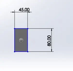
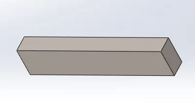
Create a rectangular by using corner rectangular or center rectangle for which sketch appropriate dimensions and convert into 2d sketch to three dimensional model by using an extrude boss base command at 400mm from the sketch.
ii) I section :
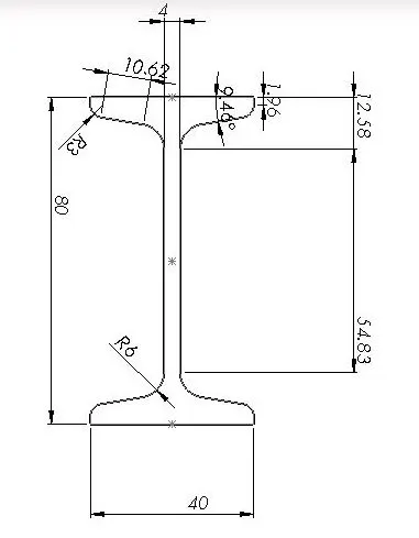
Given Cross section of beam :
Cross section of beam drawn in solidworks :
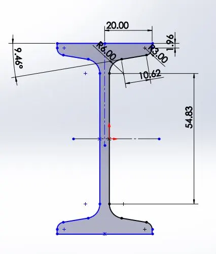
First of all, create a one fourth sketch with proper dimensions, mirroring it from the references horizontal lines. Now, we have got half of the sketch with that, mirroring the sketch from the vertical lines. Finally, we get 2d cross section of beam.
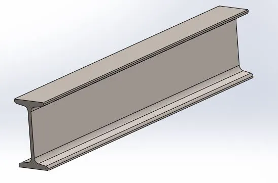
Convert from 2d sketch to 3d model by using a extrude boss bose option. The I section beam image is shown as below
iii) C Section :
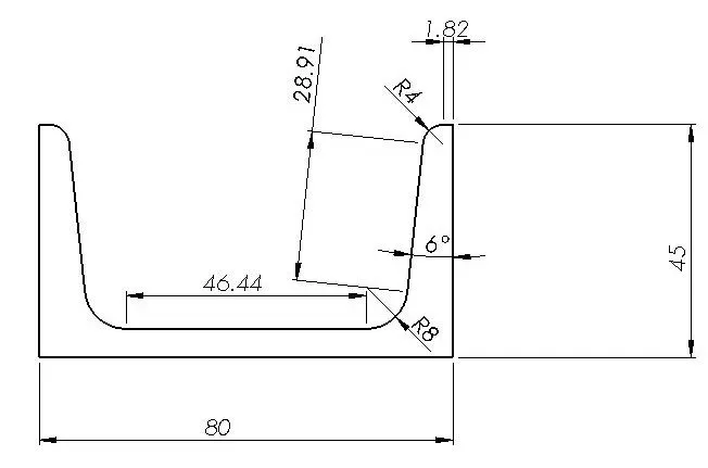
Given Cross section of beam :
Cross section of beam drawn in solidworks :
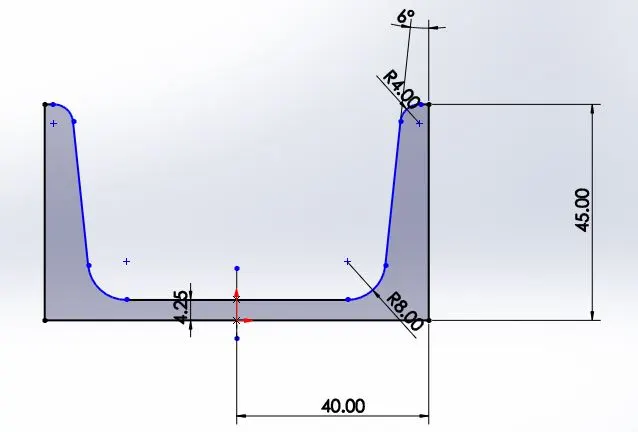
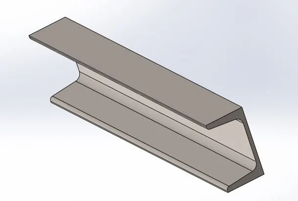
First of all, create a half of the cross section with proper dimensions, mirroring about an vertical referance line. Now, we get full cross section of beam, to extrude the drawn sketch at which distance of 400 mm on same cross section throughout the extruded length.
MATERIAL SELECTION :
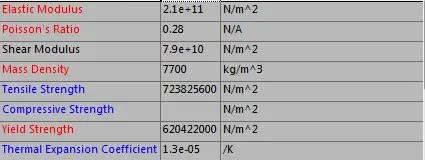
Beam material is Alloy steel for all cases.
Properties :
Model types : Linear elastic isotropic
Units : SI N/m^2 (pa)

DISCRITIATION OF BEAMS :
The process of discritize the body is divided into infinitesimal volume or finite element is called meshing. A governing equation has to be each and every element for over concerned variables.
I) Rectangular beam :
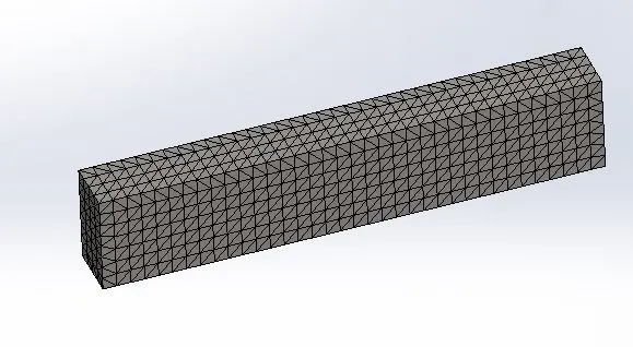
Element size - 11.2949 mm
Mesh Quality - High
Total Nodes - 11666
Total elements - 7407
II) I section beam :
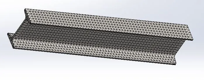
Element size - 6.86731 mm
Mesh Quality - High
Total Nodes - 18177
Total elements - 9192
III) C section beam :
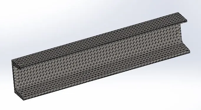
Element size - 7.32173 mm
Mesh Quality - High
Total Nodes - 15511
Total elements - 7758
INITIAL AND BOUNDARY CONDITION :
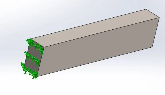
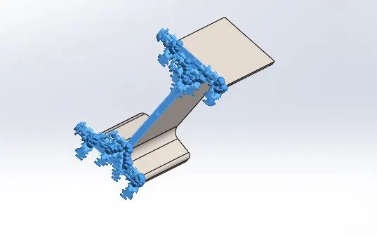
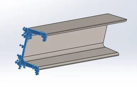
First boundary condition is one end fixed for all the cases.
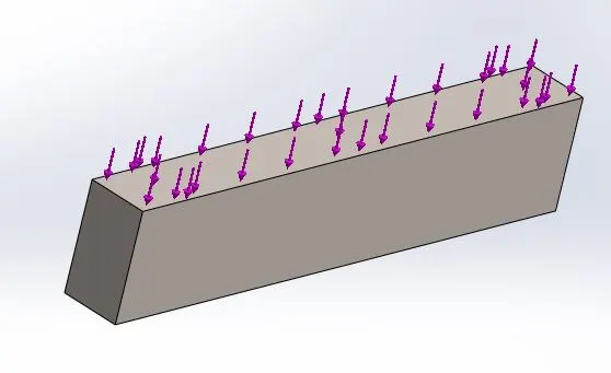
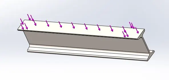
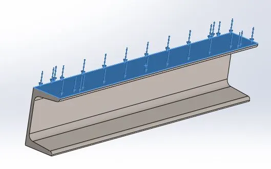
Second boundary condition is uniform distribution load applied over the smaller face of the corresponding beam at 1500 N.
I) Rectangular section :
Fixed end :
Load :
II) I section :
Fixed end :
Load :
III) C Section :
Fixed end :
Load :
POST PROCESSING :
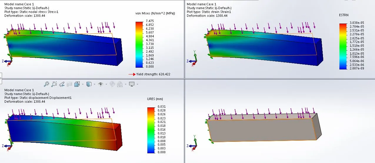
I) Rectangular beam :
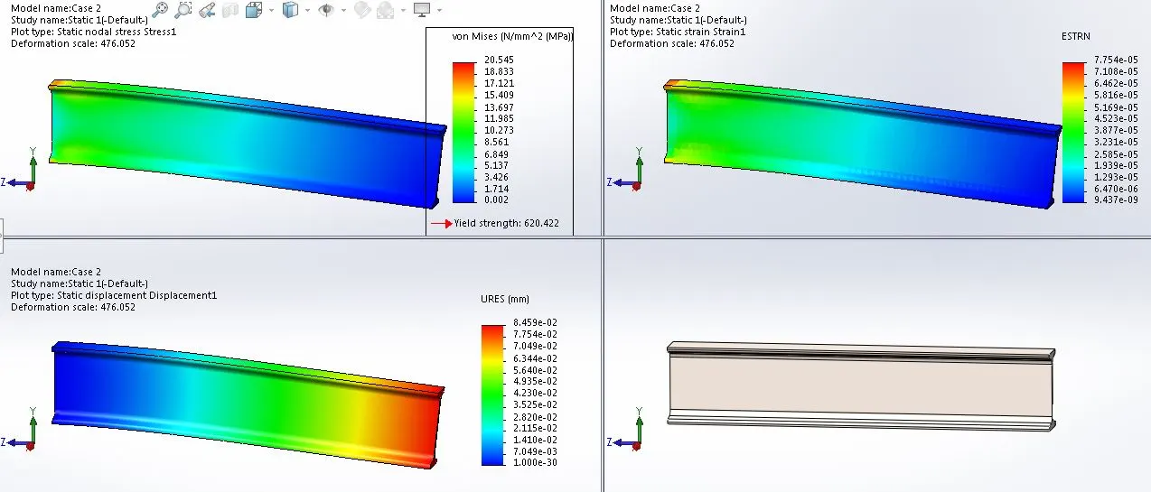
II) I Sectional beam :
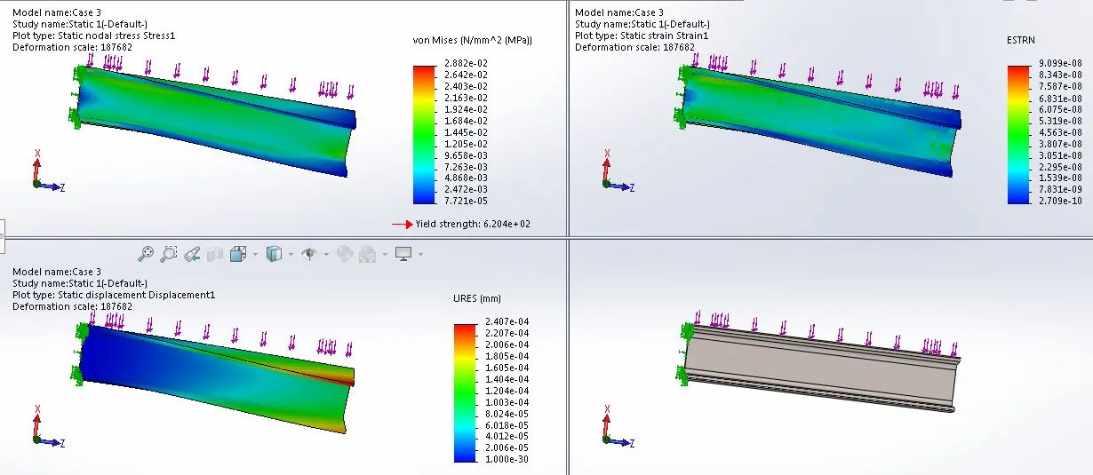
III) C Sectional beam :
OBSERVATIONS :
| Von Mises stress | Displacement | Equivalent Strain | |
| Rectangular cross sectional beam | 7.475 | 0.31 | 3.038e-05 |
| I cross sectional beam | 20.545 | 0.08459 | 7.754e-05 |
| C cross sectional beam | 0.02882 | 2.407e-04 | 9.009e-08 |
1) The maximum values are tabulated for which corresponding cases. Rectangular beam stress value is lies I & C section beams, I cross section beam has to be high resistive force upon corresponding cross sectional area. Because, cross sectional view is less.
2) Rectangular cross sectional beam displacement is high at the end of the beam. For C cross sectional beam displacement is low, the torsion have been developed.
3) Equivalent strain is less for which Cross sectional beam, I cross sectional beam strain comes between maximum and minimum.
CONCLUSION :
Finally, we had ran the three different cases from which 'I' cross sectional beam has taken less mass and less cross sectional area and also stress, strain & Displacement is quite good. So, I conclude case 2 has been good.
REFERANCE :
1) https://www.caliberdesign.co.nz/types-applications-fea/
2) https://www.twi-global.com/technical-knowledge/faqs/finite-element-analysis