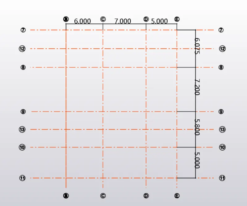
To plan a structural layout and to create grids using TSD
Questions. 1. Summarize the user interface in TSD with the for the following items: -
- Project Workspace – How to access and usage.
- Scene Content – Demonstrate the use of scene content.
- Create two scene views.
- Loading drop list- How to access.
- Properties windows – how to access and usage.
2. Create a new file in TSD and set up the settings for a steel building to have member grade FE410 and concrete grade of M30 as per IS codes. The covers for the members to be as per the following input: -
|
MEMBERS |
IN CONTACT WITH GROUND |
ABOVE GROUND |
|
Column |
50mm |
40mm |
|
Slab |
30mm |
25mm |
|
Pile cap |
75mm |
|
|
Foundation |
50mm |
3. With reference to the input drawing as per Attachment 1, 1.1, and 1.2 and study the steel building plan and summarize your understanding of the plan. Based on your study assume and explain the location of columns and beam and develop a hand sketch for each plan.
4. Model grid lines and construction levels as per Attachment 1. 1.1 and 1.2. All dimensions are in mm
- The base level to be 500mm below ground level.
Answers.
1. Summarize the user interface in TSD with the for the following items: -
- Project Workspace – How to access and usage.
- Scene Content – Demonstrate the use of scene content.
- Create two scene views.
- Loading drop list- How to access.
- Properties windows – how to access and usage.
Answer.
- Project Workspace – How to access and usage:
- First of all open the TEKLA software.
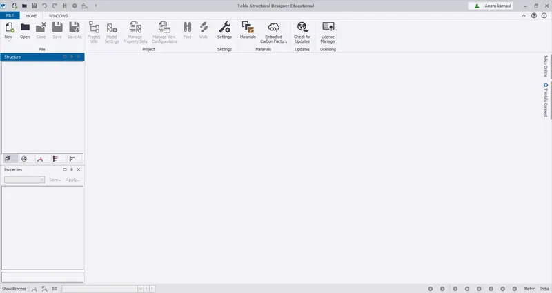
- After opening the TEKLA software, there will be an option called New in the Ribbon tab after that there will be a new workspace or we can say that Project Workspace just as shown in the below given image:
- Scene Content – Demonstrate the use of scene content:
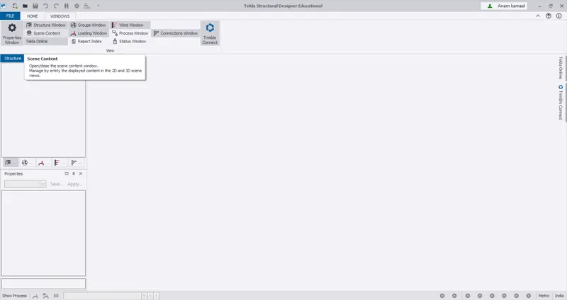
- In order to demonstrate the use of the scene content. We need to go to the window option at the top of the screen click on that option.
- There we will be able to see the option scene content click on that option just as shown in the below given image:
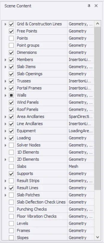
- And after this there will be another dialouge box named as the Scene content.
- And in that dialouge box there are multiple options which shows the ticked and the unticked elements in that dialouge box just as shown in the below given image:
- Create two scene views:
- In order to create the two scene views in the TSD software, go to the Model ribbon and in that ribbon box there will be an option called Model just click on that option click on that just as shown in the below given image:

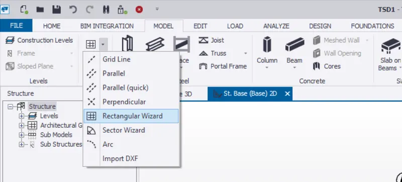
- After that there will be another option called Grids click on that option after clicking on that option there will be a drop-down list and in that list there will be multiple options to create grids.
- So we will be using the option Rectangular Wizard just click on that option after just as shown in the below given image:
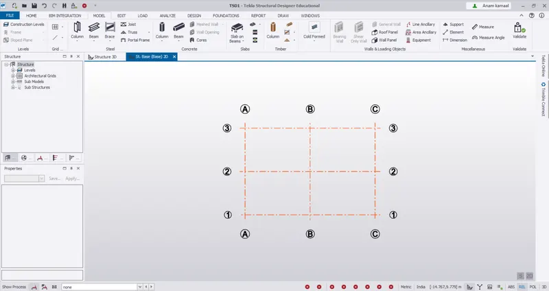
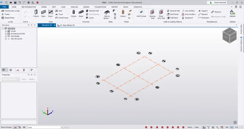
- And below is the images of 2D-view of the grid line and the 3D-view of the grid lines:
2D-View:
3D-View:
- Loading drop list- How to access:
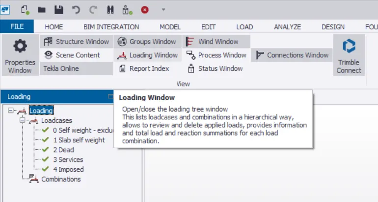
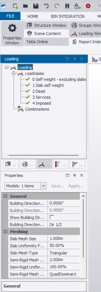
- In order to access the Loading drop down list, we will be going at the Left side of the workspace of the TSD software.
- At the left side of the workspace there will be an option called Loading window click on that option just as shown in the below given image:
- After that there will be a drop-down list of the loadings just as shown in the below given image:
- Properties windows – how to access and usage:
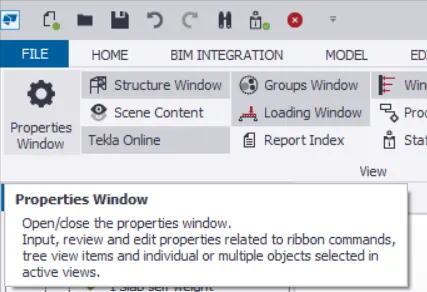
- Now in order to access the properties windows on the Left corner of the workspace there will be an Icon named as the Properties Window.
- This option helps us to Open/Close the properties window.
- So in order to open that window just click on that option just as shown in the below given image:
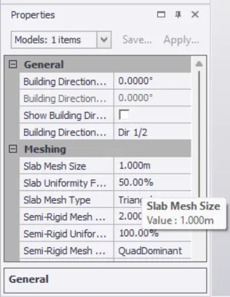
- Then there will be a dialouge box that appears at the Bottom left corner just as shown in the below given image:
2. Create a new file in TSD and set up the settings for a steel building to have member grade FE410 and concrete grade of M30 as per IS codes. The covers for the members to be as per the following input: -
|
MEMBERS |
IN CONTACT WITH GROUND |
ABOVE GROUND |
|
Column |
50mm |
40mm |
|
Slab |
30mm |
25mm |
|
Pile cap |
75mm |
|
|
Foundation |
50mm |
Solution:
Aim: To create a new file in TSD and to set up the settings for a steel building to have member grade FE410 and concrete grade of M30 as per the IS codes. And to change the cover thickness.
Procedure:
Create a New File:
- First of all open the TEKLA software.
- After opening the TEKLA software, there will be an option called New in the Ribbon tab after that there will be a new workspace or we can say that Project Workspace just as shown in the below given image:
Settings for a steel building of member grade FE410 and concrete grade of M30:
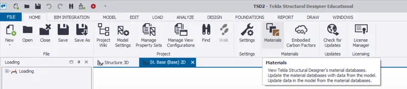
- In order to assign the materials, go to the option Material at the right side of the workspace just click on that option just as shown in the below given image:
- And now after that there will another dialouge box named as the Material just as shown in the below given image:
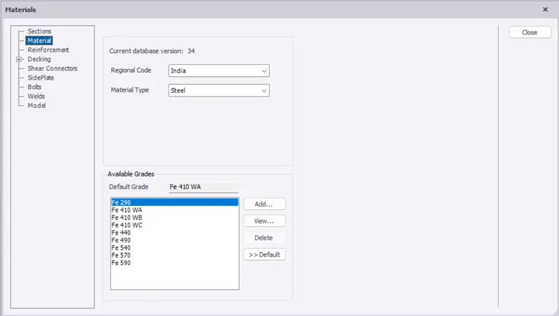
- And now there will be multiple options in that dialouge box,and in that multiple options there will be an option called Materials just click on that option after that there will be an option called Available grades and in that option fill out the all necessary data.
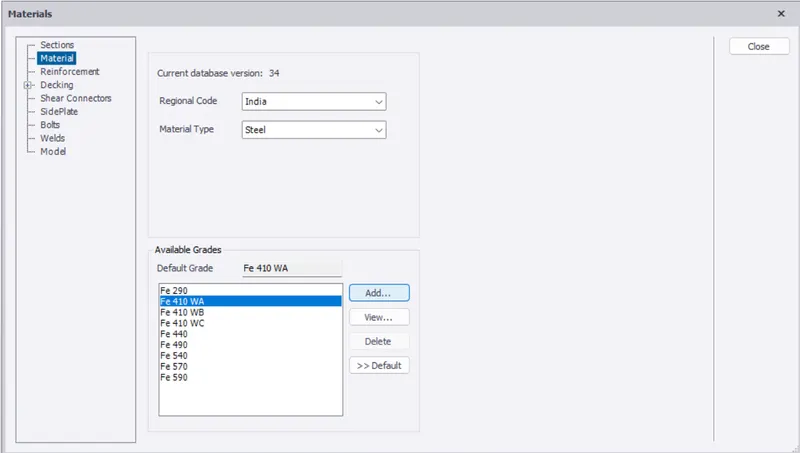
- And then select the material type as steel and grade as the FE410 just as shown in the below given image:
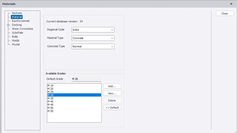
- Now select the material type as the concrete and select the Available grades as M30 just as shown in the below given image:
To change the cover thickness:
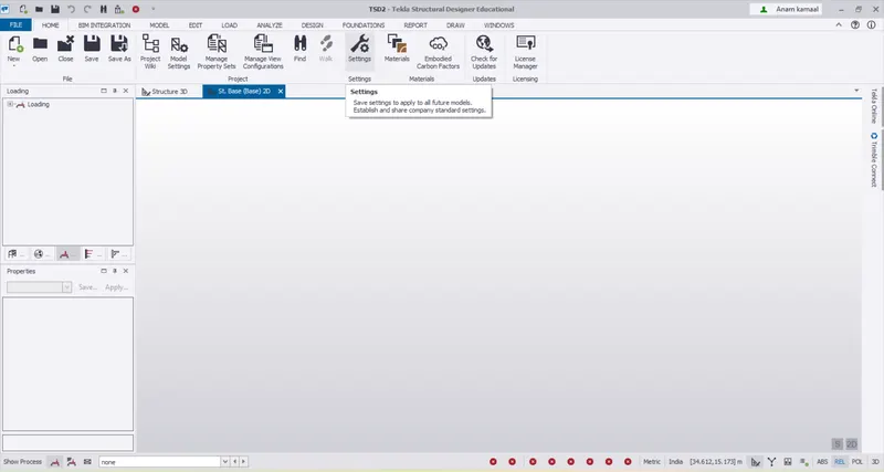
- In order to change the cover thickness,click on the settings option which is available at the top of the workspace of the TSD softaware,click on that option just as shown in the below given image:
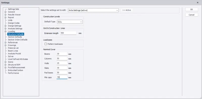
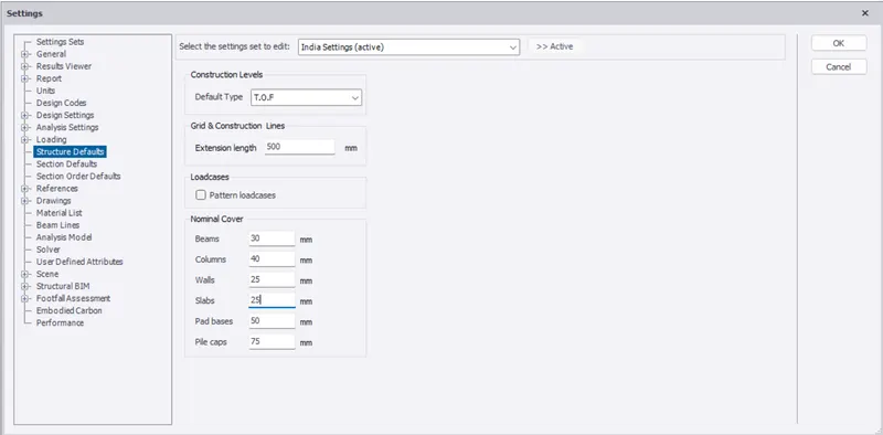
- After clicking on the option settings there will be another dialouge box name as the Settings,in that dialouge box there will be another option called Loadings and in that loadings there will be another option called Structure Defaults.
- Now select the SSL as the default type as the construction level and fill the column cover as the 50mm,slab as 30mm and pile cap as 75mm just as shown in the below given image:
- Now select TOF as default type as the construction level and fill the cover for column as 40mm,slab as 25mm and pile cap 75mm just as shown in the below given image:
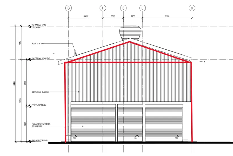
3. With reference to the input drawing as per Attachment 1, 1.1, and 1.2 and study the steel building plan and summarize your understanding of the plan. Based on your study assume and explain the location of columns and beam and develop a hand sketch for each plan.
Solution.
Aim: With reference to the input drawing as per Attachment 1, 1.1, and 1.2 and study the steel building plan and summarize your understanding of the plan. Based on your study assume and explain the location of columns and beam and develop a hand sketch for each plan.
Introduction:
- So the very first step in order to do any structural planning is to study the architectural drawing given and to check the various properties like geometry,symmetry,stiffness,redundancy etc.
- After this assigning the column and beams are done before the planning for the foundation or any other options.
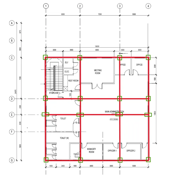
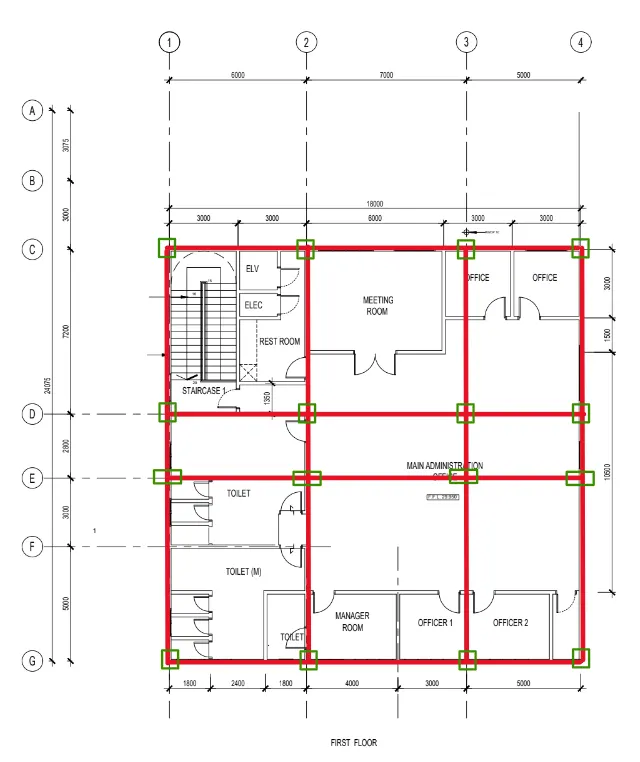
Based on my study,following are the location of the columns and the beams:
Location of columns:
- Columns are primarily placed vertically and are responsible for the supporting the weight of the structures above them.
- Strategically the columns are positioned to transfer the loads from the upper floors or roof to the foundation.
- Columns are commonly located at the corners and the intersections of the buildings.
- Columns are often placed near the openings such as the doors,windows and the large archways.
Location of Beams:
- Beams are basically positioned perpendicular to the direction of the load and are supported by the columns or the walls.
- Beams are placed horizontally,running parallel to the walls and the columns.
- Beams can also be used to resist lateral loads such as the winds or the seismic forces.
Below are the hand sketch of the plans:
GROUND FLOOOR PLAN:
FIRST FLOOR PLAN:
ELEVATION:
4. Model grid lines and construction levels as per Attachment 1. 1.1 and 1.2. All dimensions are in mm
- The base level to be 500mm below ground level.
Solution.
AIM: To model the grid lines and the construction levels as per the given attachments. The base level should be 500mm below ground level.
PROCEDURE:
- First of all open the new file in the TSD in order to create a new model workspace and in order to model the grid lines and the construction levels.
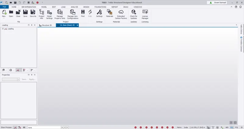
- Now the project workspace is now active and all the ribbons and the menu bars are visible just as shown in the below given image:
CONSTRUCTION LEVELS:
- First we will be creating the construction levels.
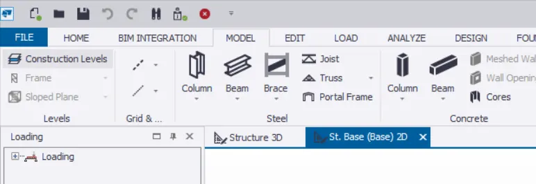
- So in order to create the construction level we will be going to the Model toolbar and in that toolbar there will be an icon named as the Construction level,click on that option just as shown in the below given image:
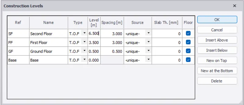
- After that there will be another dialouge box named as the Construction Levels just as shown in the below given image:
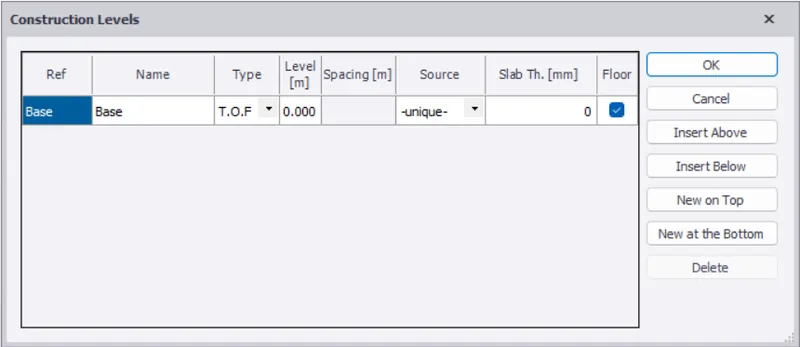
- And now after this name each levels accordingly like base,ground floor,first floor and roof according to thier respective heights which can be assigned to each level just as shown in the below given image:
GRID LINES:
- Now we will be model the grid lines.
- And in order to model the grid lines,there will be an option called grid lines,go to the Model ribbon and in that ribbon box there will be an option called Model just click on that option click on that just as shown in the below given image:
-
After that there will be another option called Grids click on that option after clicking on that option there will be a drop-down list and in that list there will be multiple options to create grids.
-
So we will be using the option Rectangular Wizard just click on that option after just as shown in the below given image:
- Below is the image of the grids: