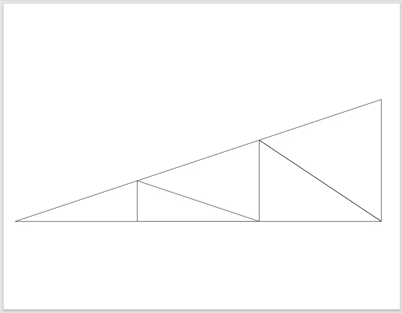
Creation of geometries by Coordinate system methods using AutoCad
Aim:
(A) To Create the geometries from P1 to P2 using all the coordinates system methods. You need to use the Line tool to create the geometries. Where required you need to use the circle tool.
Please read the drawings and find out the missing dimensions before working on the sketches.
Note: Use the Imperial Template and the Decimal Units to draft the features. Dimensions are there for
references.
Introduction:
There are three AutoCAD co-ordinate system named as :
- Absolute co-ordinates,
- Relative co-ordinates and
- Polar co-ordinates.
Absolute co-ordinates:
- All the input points specify in our drawing using standard cartesian co-ordinates x and y. Using absolute co-ordinates,points entered by typing x,y (Enter).
Relative co-ordinates:
- After first point entered,our next points can be entered by specifying the next co-ordinate compare from the first point.
- The relative co-ordinate starts with the symbol '@' .
- Using relative co-ordinate, points can be entered by typing @x,y (Enter).
Polar co-ordinates:
- Polar co-ordinates used when we need to draw the next points at specific angle.
- Using polar co-ordinates,points entered by typing @distance.
Procedure:
P1:
A) Absolute co-ordinate system:
- Open the AutoCAD application.
- Type QNEW in the command bar and enter.
- Selct default setting as Imperial(feet and inches).
- In default setting click on use wizard and in that advance setting use unit as decimal and precision as 0 and press next.
- Set angle as decimal degree and precision 0 and press next.
- Set angle measure as EAST and press next.
- Set angle direction as Counter-clockwise and press next.
- Set area by providing Length as 10 and width as 10.
- Press finish.
- From home tab click on line command.
- Specify first point in command bar (2,1).
- Specify next point as (8,1).
- Specify next point as (8,2).
- Specify next point as (3,2).
- Specify next point as (3,6).
- Specify next point as (8,6).
- Specify next point as (8,7).
- Specify next point as (2,7).
- Click on close command in command bar.
- Then the geometry is done.
(B) Relative rectangular co-ordinate system:
- Click on the AutoCAD application and open this application.
- Type QNEW in the command bar and enter.
- Selct default setting as Imperial(feet and inches).
- In default setting click on use wizard and in that advance setting use unit as decimal and precision as 0 and press next.
- Set angle as decimal degree and precision 0 and press next.
- Set angle measure as EAST and press next.
- Set angle direction as Counter-clockwise and press next.
- Set area by providing Length as 10 and width as 10.
- Press finish.
- From home tab click on line command.
- Specify first point in command bar (2,1).
- Specify next point as (@6,0).
- Specify next point as (@0,1).
- Specify next point as (@-5,0).
- Specify next point as (@0,4).
- Specify next point as (@5,0).
- Specify next point as (@0,1).
- Specify next point as (@-6,0).
- Click on close command in command bar.
- Then the geometry is done.
(C) Relative polar co-ordinate system:
- Click on the AutoCAD application and open this application.
- Type QNEW in the command bar and enter.
- Selct default setting as Imperial(feet and inches).
- In default setting click on use wizard and in that advance setting use unit as decimal and precision as 0 and press next.
- Set angle as decimal degree and precision 0 and press next.
- Set angle measure as EAST and press next.
- Set angle direction as Counter-clockwise and press next.
- Set area by providing Length as 10 and width as 10.
- Press finish.
- From home tab click on line command.
- Specify first point in command bar (2,1).
- Specify next point as (@6<0) (Towards East).
- Specify next point as (@1<90).(Towards North).
- Specify next point as (@5<180).(Towards West).
- Specify next point as (@4<,90).(Towards North).
- Specify next point as (@5<0).(Towards East).
- Specify next point as (@1<90).(Towards North).
- Specify next point as (@6<80).(Towards West).
- Click on close command in command bar.
- Then the geometry is done.
Result: 
P2:
A) Absolute co-ordinate system:
- Open the AutoCAD application.
- Type QNEW in the command bar and enter.
- Selct default setting as Imperial(feet and inches).
- In default setting click on use wizard and in that advance setting use unit as decimal and precision as 0 and press next.
- Set angle as decimal degree and precision 0 and press next.
- Set angle measure as EAST and press next.
- Set angle direction as Counter-clockwise and press next.
- Set area by providing Length as 10 and width as 10.
- Press finish.
- From home tab click on line command.
- Specify first point in command bar (2,1).
- Specify next point as (5,1).
- Specify next point as (5,5).
- Specify next point as (6,5).
- Specify next point as (6,1).
- Specify next point as (9,1).
- Specify next point as (7,8).
- Specify next point as (4,8).
- Click on close command in command bar.
- Then the geometry is done.
(B) Relative rectangular co-ordinate system:
- Click on the AutoCAD application and open this application.
- Type QNEW in the command bar and enter.
- Selct default setting as Imperial(feet and inches).
- In default setting click on use wizard and in that advance setting use unit as decimal and precision as 0 and press next.
- Set angle as decimal degree and precision 0 and press next.
- Set angle measure as EAST and press next.
- Set angle direction as Counter-clockwise and press next.
- Set area by providing Length as 10 and width as 10.
- Press finish.
- From home tab click on line command.
- Specify first point in command bar (2,1).
- Specify next point as (@3,0).
- Specify next point as (@0,4).
- Specify next point as (@1,0).
- Specify next point as (@0,-4).
- Specify next point as (@3,0).
- Specify next point as (@-2,7).
- Specify next point as (@-3,0).
- Click on close command in command bar.
- Then the geometry is done.
(C) Relative polar co-ordinate system:
- Click on the AutoCAD application and open this application.
- Type QNEW in the command bar and enter.
- Selct default setting as Imperial(feet and inches).
- In default setting click on use wizard and in that advance setting use unit as decimal and precision as 0 and press next.
- Set angle as decimal degree and precision 0 and press next.
- Set angle measure as EAST and press next.
- Set angle direction as Counter-clockwise and press next.
- Set area by providing Length as 10 and width as 10.
- Press finish.
- From home tab click on line command.
- Specify first point in command bar (2,1).
- Specify next point as (@3<0).
- Specify next point as (@4<90).
- Specify next point as (@1<180).
- Specify next point as (@4<,270).
- Specify next point as (@3<0).
- Specify next point as (@7<106).
- Specify next point as (@3<180).
- Click on close command in command bar.
- Then the geometry is done.
Result: 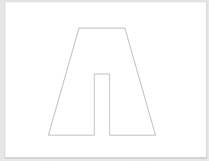
P4:
Using Absolute co-ordinate system:
- Open the AutoCAD application.
- Type QNEW in the command bar and enter.
- Selct default setting as Imperial(feet and inches).
- In default setting click on use wizard and in that advance setting use unit as decimal and precision as 0 and press next.
- Set angle as decimal degree and precision 0 and press next.
- Set angle measure as EAST and press next.
- Set angle direction as Counter-clockwise and press next.
- Set area by providing Length as 10 and width as 10.
- Press finish.
- From home tab click on line command.
- Specify first point in command bar (2,1).
- Specify next point as (3,1).
- Specify next point as (3,5).
- Specify next point as (5,3).
- Specify next point as (7,5).
- Specify next point as (7,1).
- Specify next point as (3,1).
- Specify next point as (8,8).
- Specify next point as (7,8).
- Specify next point as (5,5).
- Specify next point as (3,8).
- Specify next point as (2,8).
- Click on close command in command bar.
- Then the geometry is done.
Result: 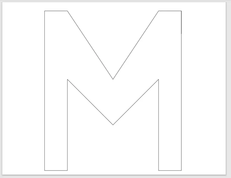
P5:
Relative rectangular co-ordinate system:
- Open the AutoCAD application.
- Type QNEW in the command bar and enter.
- Selct default setting as Imperial(feet and inches).
- In default setting click on use wizard and in that advance setting use unit as decimal and precision as 0 and press next.
- Set angle as decimal degree and precision 0 and press next.
- Set angle measure as EAST and press next.
- Set angle direction as Counter-clockwise and press next.
- Set area by providing Length as 10 and width as 10.
- Press finish.
- From home tab click on line command.
- Specify first point in command bar (2,1).
- Specify next point as (@1,0).
- Specify next point as (@0,7).
- Specify next point as (@5,0).
- Specify next point as (@0,-6).
- Specify next point as (@-3,0).
- Specify next point as (@0,-1).
- Specify next point as (@4,0).
- Specify next point as (@0,8).
- Specify next point as (@-7,0).
- Click on close command in command bar.
- Then the geometry is done.
Result: 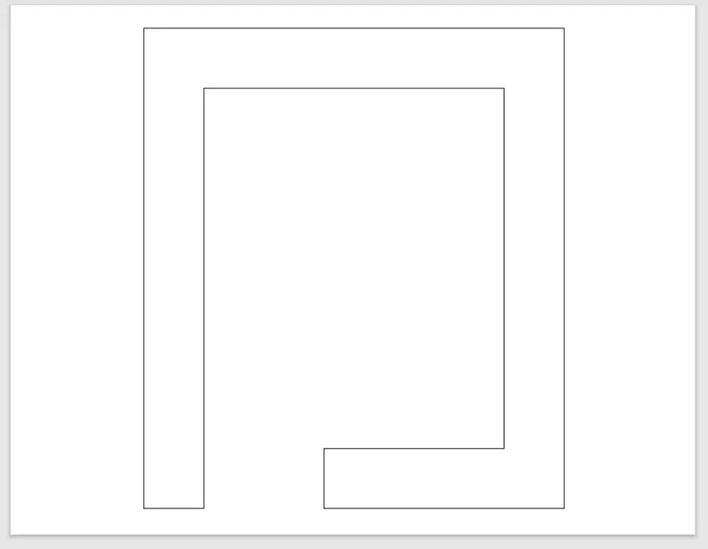
P7:
Using Absolute co-ordinate system:
- Select LINE tool from the ribbon or type LINE command in the command bar.
- Specify first point in command bar (2,1).
- Specify next point as (10,1).
- Specify next point as (10,7).
- Specify next point as (2,7).
- Click on CLOSE in command line.
- Select LINE tool from the ribbon or type LINE command in the command bar.
- Specify first point as (3,2).
- Specify next point as (5,2).
- Specify next point as (5,5).
- Specify next point as (3,5).
- Click on CLOSE in command line.
- Select LINE tool from the ribbon or type LINE command in the command bar.
- Specify first point as (6,2).
- Specify next point as (8,2).
- Specify next point as (8,5).
- Specify next point as (6,5).
- Click on close command in command bar.
- Then the geometry is done.
Result: 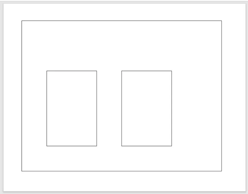
P8:
Using Relative rectangular coordinate system:
- Select LINE tool from the ribbon or type LINE command in the command bar.
- Specify first point in command bar (0,0).
- Specify next point as (@10,0).
- Specify next point as (@0,2).
- Specify next point as (@-4,0).
- Specify next point as (@0,4).
- Specify next point as (@3,0).
- Specify next point as (@0,2).
- Specify next point as (@-8,0).
- Specify next point as (@0,-2).
- Specify next point as (@3,0).
- Specify next point as (@0,-4).
- Specify next point as (@-4,0).
- Click on close command in command bar.
- Then the geometry is done.
Result: 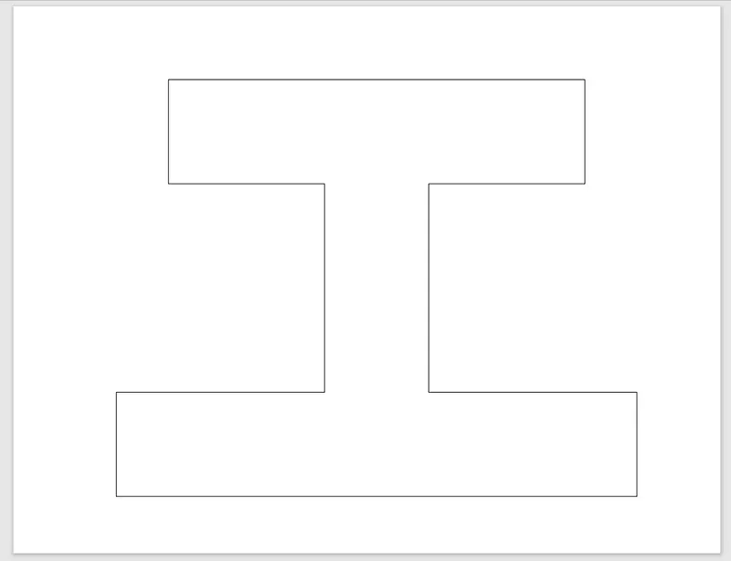
P9:
Using Absolute co-ordinate system:
- Select LINE tool from the ribbon or type LINE command in the command bar.
- Specify first point in command bar (1,1).
- Specify next point as (6,1).
- Specify next point as (6,3).
- Specify next point as (3,3).
- Specify next point as (3,2).
- Specify next point as (2,2).
- Specify next point as (2,4).
- Specify next point as (5,4).
- Specify next point as (5,6).
- Specify next point as (1,8).
- Click on close command in command bar.
- Then the geometry is done.
Result: 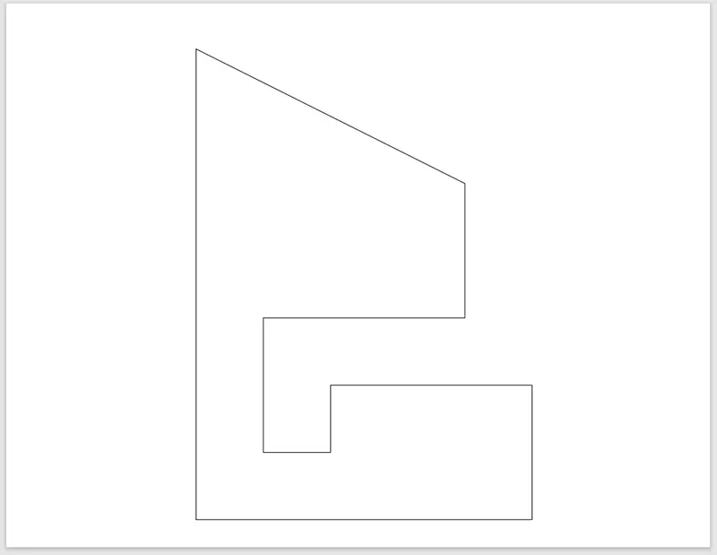
P10:
Using Relative Polar co-ordinate system:
- Select LINE tool from the ribbon or type LINE command in the command bar.
- Specify first point in command bar (1,1).
- Specify next point as (@2<0).
- Specify next point as (@3<90).
- Specify next point as (@3<0).
- Specify next point as (@4<90).
- Specify next point as (@5<180).
- Click on close command in command bar.
- Select LINE tool from the ribbon or type LINE command in the command bar.
- Specify first point as (2,5).
- Specify next point as (@3<0).
- Specify next point as (@2<90).
- Specify next point as (@3<180).
- Click on close command in command bar.
- Then the geometry is done.
Result: 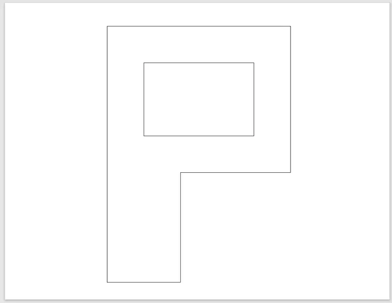
(B) Aim: Civil Related Problems
Draw the profile and the trusses using any coordinate system methods. The dimensions are there for references.
Procedure:
Profile Wood :
- Click on the AutoCAD application and open this application.
- Type QNEW in the command bar and enter.
- Selct default setting as Imperial(feet and inches).
- In default setting click on use wizard and in that advance setting use unit as decimal and precision as 0 and press next.
- Set angle as decimal degree and precision 0 and press next.
- Set angle measure as EAST and press next.
- Set angle direction as Counter-clockwise and press next.
- Set area by providing Length as 10 and width as 10.
- Press finish.
- From home tab click on line command.
- Specify first point in command bar (0,0).
- Specify next point as (10,0).
- Specify next point as (10,1).
- Specify next point as (8,1).
- Specify next point as (8,5).
- Specify next point as (10,5).
- Specify next point as (10,6).
- Specify next point as (10,9).
- Specify next point as (5,9).
- At the end of the pointline 2(H) join the line from H to G and delete the line 1 and 2.
- Line command at the point H.
- Specify next point as (0,9).
- Specify next point as (0,6).
- At the end point of line 4 is I join the line from the I to H and delete line 3 and 4.
- Line command at the point I.
- Specify next point as (2,6).
- Specify next point as (2,1).
- Specify next point as (0,1).
- Click on close command in command bar.
- Draw a circle of point (5,4) at radius 2.
- Click on close command in command bar.
- Then the geometry is done.
Result: 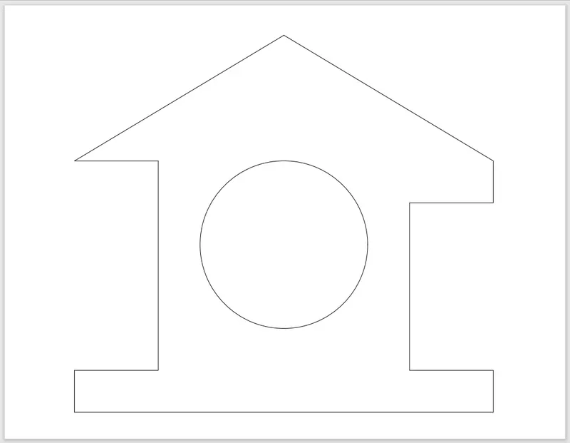
Queen Post Truss:
- Click on the AutoCAD application and open this application.
- Type QNEW in the command bar and enter.
- Selct default setting as Imperial(feet and inches).
- In default setting click on use wizard and in that advance setting use unit as decimal and precision as 0 and press next.
- Set angle as decimal degree and precision 0 and press next.
- Set angle measure as EAST and press next.
- Set angle direction as Counter-clockwise and press next.
- Set area by providing Length as 10 and width as 10.
- Press finish.
- From home tab click on line command.
- Specify first point in command bar (1,1).
- Specify next point as (@4<90).
- Specify next point as (@7<0).
- Click on close command in command bar.
- From home tab click on line command.
- Specify first point as (1,5).
- Specify next point as (@5<45).
- Click on close command in command bar.
- From home tab click on line command.
- Specify next point as (8,5).
- Specify next point as (@5<135).
- Specify next point as (@3.5<270).Point A
- Click on close command in command bar.
- From home tab click on line command.
- Specify next point as (1,5).
- Specify next point as (@1<0).
- Specify next point as (@1<90).Point B
- Using line command join point A and B.
- Click on close command in command bar.
- From home tab click on line command.
- Specify next point as (8,5).
- Specify next point as (@1<180).
- Specify next point as (@1<90). Point C
- Using line command join point B and C.
- Click on close command in command bar.
- Then the geometry is done.
Result: 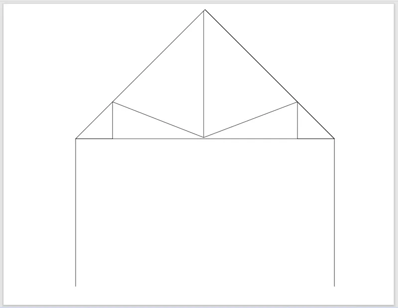
Mono Pitch:
By using Absolute co-ordinate system:
- Click on the AutoCAD application and open this application.
- Type QNEW in the command bar and enter.
- Selct default setting as Imperial(feet and inches).
- In default setting click on use wizard and in that advance setting use unit as decimal and precision as 0 and press next.
- Set angle as decimal degree and precision 0 and press next.
- Set angle measure as EAST and press next.
- Set angle direction as Counter-clockwise and press next.
- Set area by providing Length as 10 and width as 10.
- Press finish.
- From home tab click on line command.
- Specify first point in command bar (1,1). Point A
- Specify next point as (3,1). Point B
- Specify next point as (3,1.667).Point C
- Specify next point as (5,1). Point D
- Specify next point as (5,2.333).Point E
- Specify next point as (7,1). Point F
- Specify next point as (7,3).Point G
- Specify next point as (1,1). Point H
- Click on close command in command bar.
- From home tab click on line command at point B.
- Specify next point as (3,1). Point I
- Specify next point as (5,1). Point J
- Specify next point as (7,1). Point K
Result: