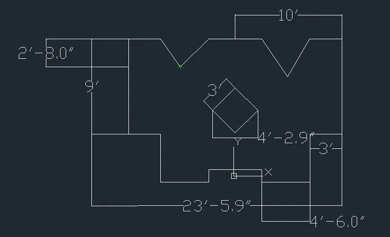
Drafting of various geometries using Chamfer, Fillet tool in AutoCad
Aim: To draft the various geometries using Chamfer,fillet tool in the AutoCAD.
Introduction: AutoCAD gives us a various tools and functions for improving the designing thus enhancing the easiness, some of the various tools include chamfer,fillet,rotate,mirror,offset and many more to enhance the designing.
Procedure:
Type QNEW in the command line and then press Enter.
Now click on the option of advance setup, then go to the set the units set the units as decimals as precision 0.000
Set angles,as Decimal degree.
Take east as the angle measurement.
Angle direction as counter-clockwise.
And select area,the width and the length of the page.
Image 1:
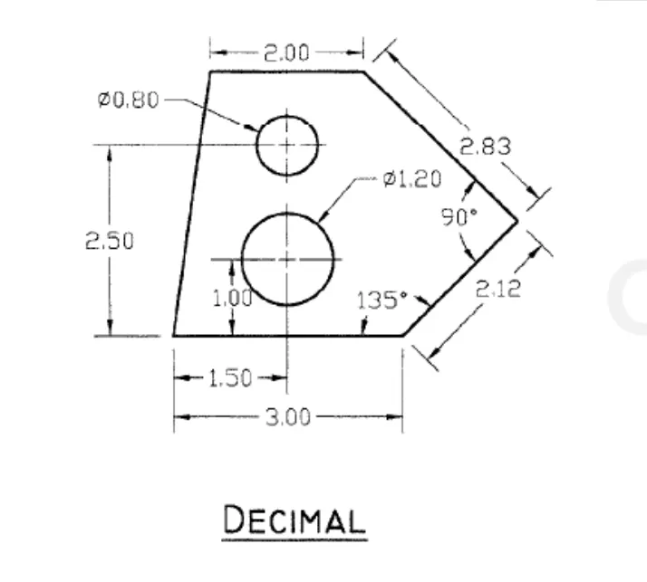
Procedure:
Type L in the command box and then press Enter.
Specify the first start point 1,1.
Specify the nex point @3,0.
Specify the nex point @2.12<45.
Specify the nex point @2.83<135.
Specify the nex point @2<180.
Now type objectsnap in the command line and then press Enter and then click on for the END-POINT and MID-POINT.
Select the mid point of the base line with 3m length.
Now type L in the command line and then press Enter.
Specify the first point (mid point of the base line).
Specify the next point @1<90.
Now type circle in the command line and then press Enter.
Click on the option Centre-diameter and provide the last point as the centre of the circle and type the diameter as 1.20.
Now delete the line joining the points i.e, mid point of 3m length line and @1<90.
Now again select the mid point of the base line with 3m and draw a line making the mid-points as the start point,to the next point as @2.50<90.
Now delete that line which is joining the points,mid point of the 3m line and @2.50<90.
Now the geometry is completed.
Result:
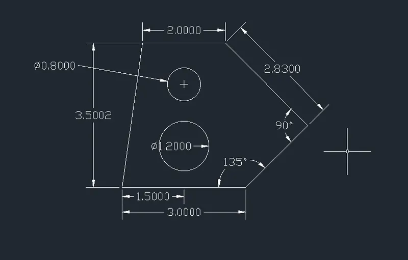
Image 2:
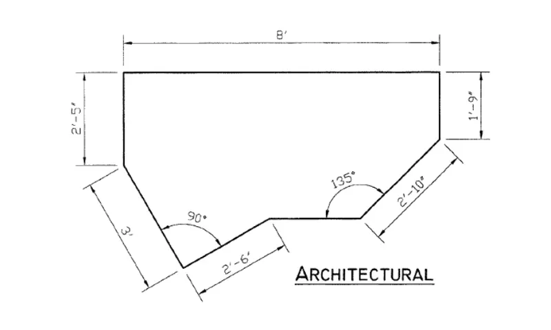
Procedure:
In advanced setup select the architectural and set the precision to 0'-0".
Now select the polar tracking as 45,90,135,180.
Now type L in the command line and then press Enter.
Select a specific first point.
Now point the cursor to the left with an angle of 135 and type the distance as 3'.
Now point the cursor to the right with an angle of 45, and type the distance as 2'-6".
Now point the cursor to the right with an angle of 0,and type the distance as 3'-1".
Now point the cursor to the right with an angle of 45, and type the distance as 1'-5".
Now point the cursor to the right with an angle of 90, and type the distance as 1'-9".
Now point the cursor to the right with an angle of 180, and type the distance as 8'.
Now close,the geometry is completed.
Result:
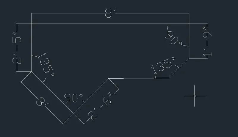
Image 3:
Procedure:
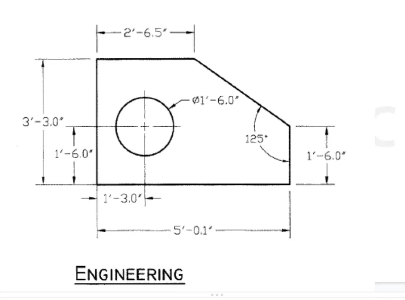
In advanced setup select Engineering and set the precision to 0'-0".
Type L in the command box and then press Enter.
Specify the first point.
Specify the next point as 5'-10" at an angle 0.
Specify the next point as 3'3" at an angle of 90.
Specify the next point as 2'-6.5" at an angle 0.
And type the close in the command line.
Now type L in the command line and then press Enter.
Specify the first point.
Specify the next point as 1'-6.0".
Now close it to make a closed figure.
Now type L in the command line an then press Enter.
Specify the first point a.
Specify the next point as 1'-3.0". in the base line and draw a line at an angle of 90 degree with length 1'-6.0".
Now use the circle command and click on the centre-diameter command in the circle.
And provide the last point as the centre of the circle with diameter of 1'-6".
Now delete the perpendicular line.
And the geometry is done.
Result:
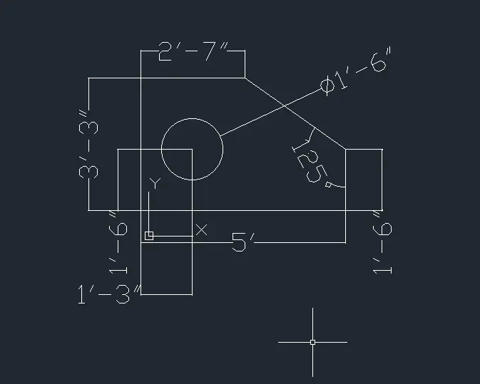
Image 4:
Procedure:
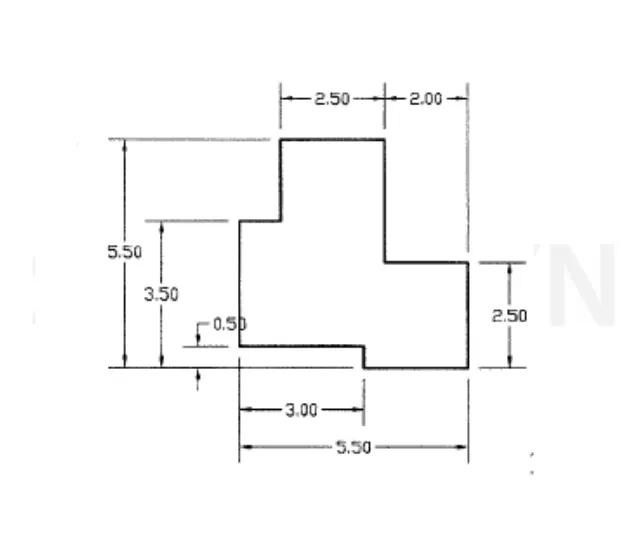
In advanced setup, select decimal and set the precision as 0.0.
Type PL or polyline in the command line and then press Enter.
Specify the starting point as any random point.
Switch ON the ortho mode.
Specify the next point as 3.0.
Specify the next point as 0.5.
Specify the next point as 2.5.
Specify the next point as 2.5.
Specify the next point as 2.
Specify the next point as 3.
Specify the next point as 2.5.
Specify the next point as 2.
Now press the ESC.
Now start from the initial point to the length 3.
Now join these two lines.
And the geometry is done.
Result:
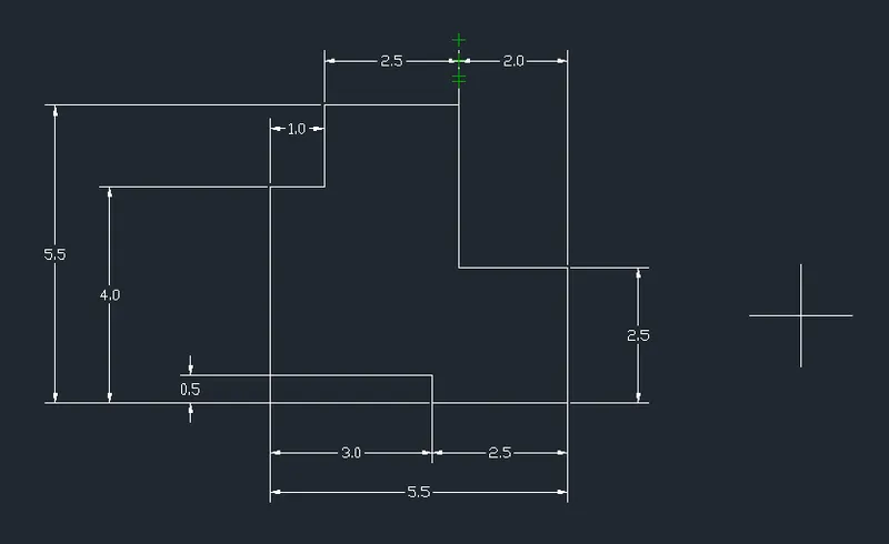
Image 5:
Procedure:
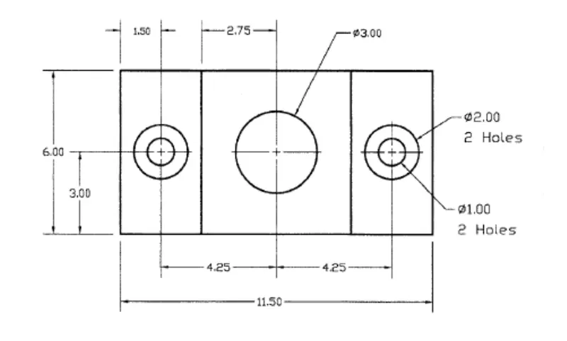
In advance setup, select the Decimal and set the precision to 0.0.
Type Rec or rectangle in the command line and then press Enter.
Specify the first point as 1,1.
Specify the next corner point as 11.50,6.0.
Draw a line at both the extreme side of the rectangle and make an offset of distance about 3 from each side.
Turn on the OSNAP and find the mid of the rectangle and draw three lines of distance 3.
For the outer circle use the option centre-diameter in circle and provide the end point of the line as the centre of the circle and diameter as 2 .
For inner circles, use the option centre-diameter in circle and provide the end point of the line as the centre od the circle and diameter as 1.
Now erase the previously drawn lines.
And the geometry is done.
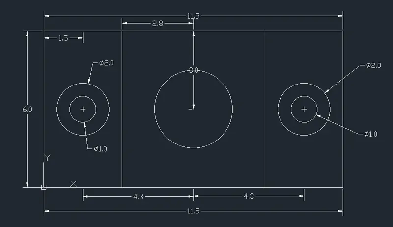
Image 6:
Procedure:
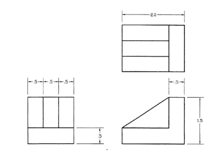
In advanced setup,select Decimal and set the precision to 0.0.
Type Rec or Rectangle in the command line and then press Enter.
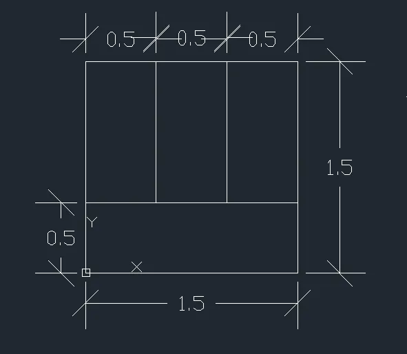
Specify the first corner as 0,0.
Specify the next corner as 1.5,0.5.
Now type L or line in the command line and then press Enter.
Specify the first point.
Specify the next point 0.5 which is perpendicular to the last point.
Type Off or offser in the command line and then press Enter.
Create two offset of distance 0.5 each.
Now join the top using the line tool.
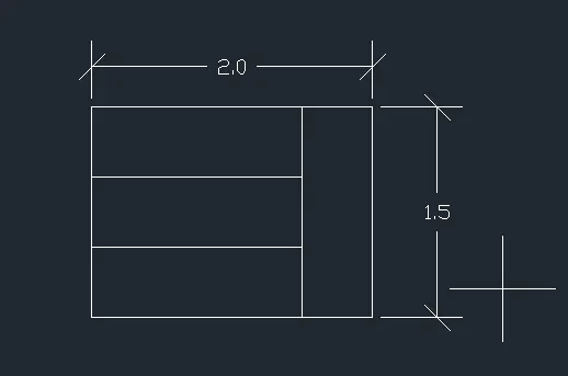
Type L or line in the command line and then press enter.
Specify the next point distance as 2.0.
Specify the next point distance as 1.5.
Using offset,make an offset of distance 0.5 from vertical.
Specify the next point distance as 0.5.
Type Off or offset in the command line and then press Enter.
Draw two offset line of distance 0.5 each.
Now join the edges.
Extend the two drawings.
Join the intersection points using the move command.
Trim the unwanted lines with the help of Trim command.
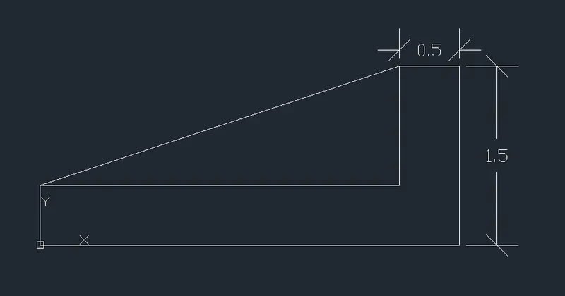
The geometry is done.
Result:
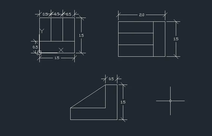
Image 7:
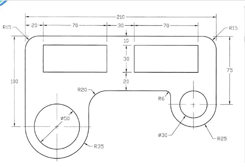
Procedure:
In Advance setup,select the Decimal and set the precision to to 0.0.
Type L or line in the command line and then press Enter.
Then draw a line of distance 100.
Draw another line with distance 210.
And another line with distance 75.
Now type Fillet in the command line and then press Enter.
Give the fillet radius as 15.
And then select the line on which we want to use the fillet command.
From the end point of 100 measure line draw a horizontal line at 70.
Select centre-radius from circle tool.
Select the mid-point of the previous line and radius as 35.
Select, centre-diameter from the circle tool.
The centre is the centre of the previous circle nd the diameter is 50.
From the end point of the line 70,draw a vertical line of 40.
Now from the end point of the 75, draw a draw a horizontal line of 50.
Now select the centre-radius option from the circle tool.
Specify the radius of 25.
Now again select the centre-diameter option from the circle tool.
And specify the diameter as 30.
From the last point of the line 50, draw a vertical line of 15.
Now complete the geometry with the line command.
Now type fillet in the command bar and then press Enter.
Select the lines which we want to fillet.
Now specify the fillet radius as 6.
Select the lines.
Now type a rec or rectangle in the command line and then press Enter.
Specify the first corner point as 20,10.
Specify the next corner point 30,70.
Using the offset command,offset the rectangle using the offset command at a distance of 30.
Now trim the unwanted lines.
And the geometry is done.
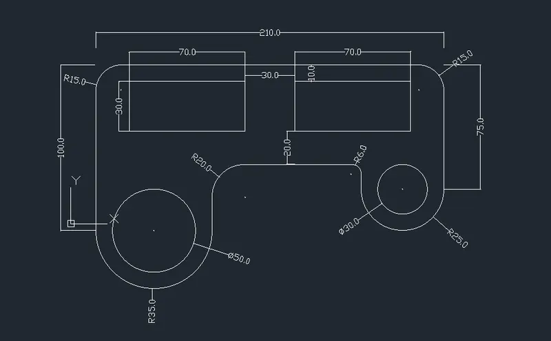
Image 8:
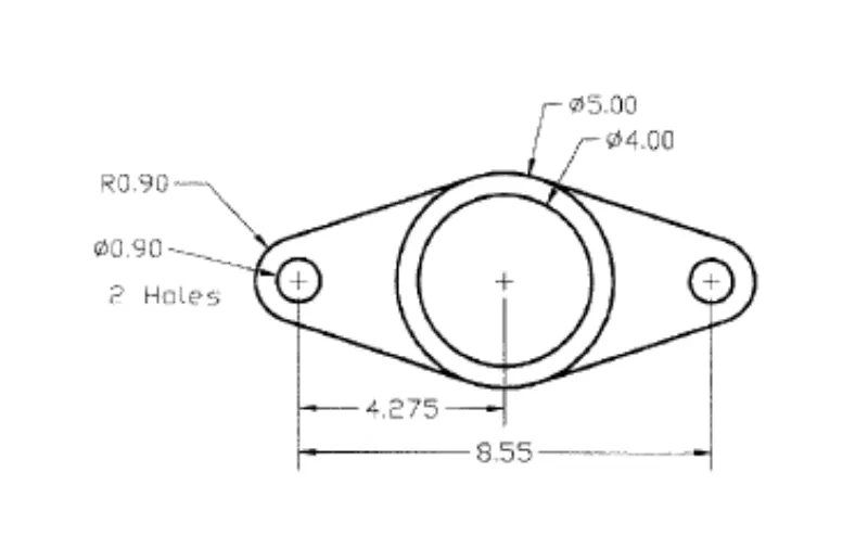
Procedure:
Type L in the command line and then press Enter.
Draw a line of distance 8.55.
From the menu bar select the centre-diameter option from the circle tool.
Specify the diameter of the circle as 0.9.
Now from menu bar select centre-radius option from the circle tool.
Specify the radius of the circle as 0.9.
Now repeat the same procedure for making the circle of radius 0.9 and diameter of 0.9 at the other end of the line of distance 8.55.
Again select the centre-diameter option from the circle tool. And this time the centre of the circle is the centre of the line of distance 8.55.
Specify the diameter of the circle as 4.00.
Specify the another diameter of the circle as 5.00.
Now join the tangents of the outer circle using line.
And trim the unwanted lines.
And the geometry is done.
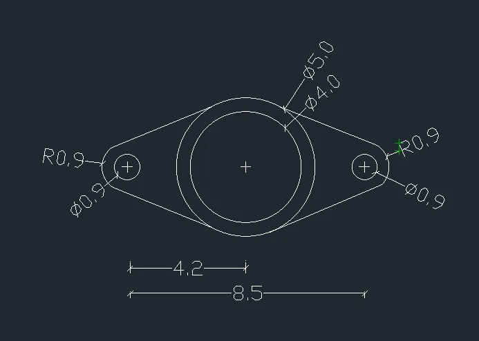
Image 9:
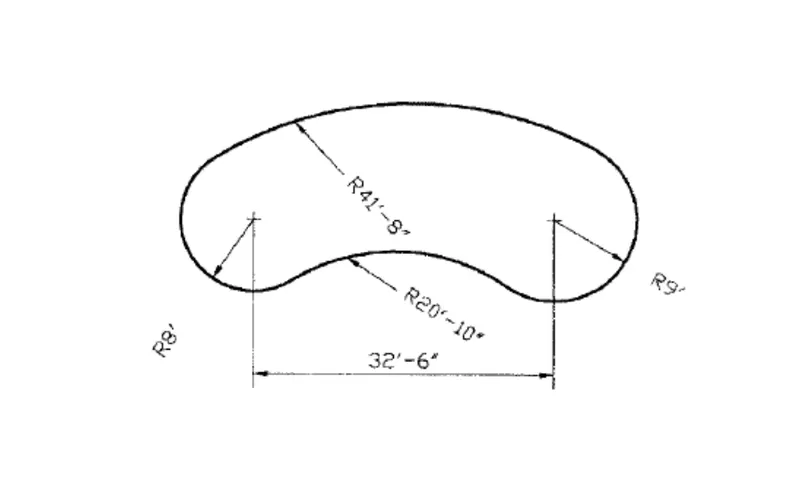
Procedure:
Type UN an press enter.
Under drawing units,select the desired unit i.e, Engineering units.
Type L in the command line and then press Enter.
Specify the start point 5',5'.
Specify the next point @32'-6",0.
Type C in the command line and then press Enter.
Specify the centre point of the circle 5',5'.
Specify the radius of the circle 8'.
Type C in the command line and then press Enter.
Specify the centre point of the circle 5',5'.
Specify the radius of the circle 9'.
Type C an then press Enter.
Select tan,tan,radius.
Select first tangent by clicking on top tangent of the right circle.
Now select second tangent by clicking on the top tangent of the left circle.
Specify radius as 41'-8".
Type C an then press Enter.
Select tan,tan,radius.
Select first tangent by clicking on top tangent of the right circle.
Now select second tangent by clicking on the top tangent of the left circle.
Specify radius as 41'-8".
Type C an then press Enter.
Select tan,tan,radius.
Select first tangent by clicking on bottom tangent of the right circle.
Now select second tangent by clicking on the bottom tangent of the left circle.
Specify radius as 20'-10".
Trim the unwanted parts to get the geometry.
The geometry is done.
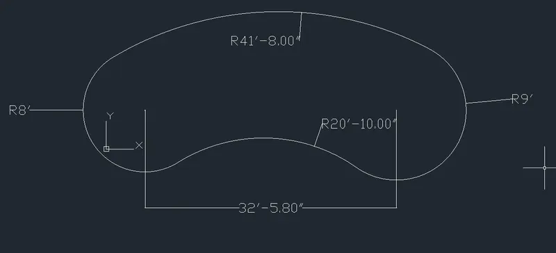
Image 10:
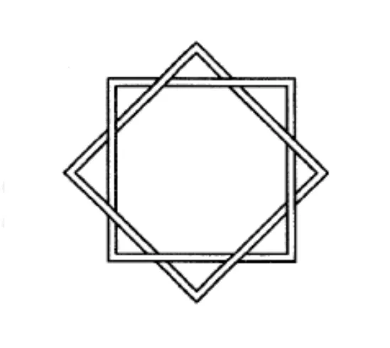
Procedure:
Type UN and then press Enter.
Under drawing units,select the desired unit i.e, Decimal units.
Type Rec or Rectangle in the command line and then press Enter.
Specify the first corner of the rectangle.
Enter D for dimensions.
Enter the length : 10.
Enter the Width : 10.
Specify the other corner.
Type O or Offset in the command line and then press Enter.
Specify the value of offset distance 0.5.
Select the object to offset and click inside the rectangle.
Type RO and then press Enter.
Select the object which has to be rotate i.e, Rectangle.
And rotate it by angle 45 degree by selecting a base point.
Move the rotated rectangle and place it at the centre.
Trim of the additional lines.
And the geometry is done.
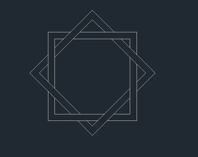
Image 11:
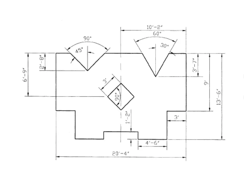
Procedure:
Type UN in the command line and then press Enter.
Under drawing units,select the desired unit i.e, Engineering.
Type L in the command line and then press Enter.
Specify the starting point.
Specify the next point @ 2'-6",0.
Specify the next point @0,-1'-2".
Specify the next point @4'-6",0.
Specify the next point @0,4'-6".
Specify the next point @3',0.
Specify the next point @0,9'.
Type MI in the command line and then press Enter.
Select the mirror objects.
Specify the first point of the mirror object.
Specify the second point at top.
Type L in the command line and then press Enter.
Specify the starting point.
Specify the next point @0,3'-7".
Specify the next point @ -8'-7",0.
Turn on the polar tracking for 30,60,90 degree.
With d as the centre draw a line at an angle of 30 degree till it touches the bottom line and 120 degree towards the up and close the figure.
Type L in the command line and then press Enter.
Specify the start point.
Specify the next point @0,2'-8".
Specify the next point @6'-7",0.
Turn on the polar tracking for 45,90,135 degree.
With d as the centre draw a line at an angle of 45 degree till it touches the line and 135 degree towards up and close the figure.
Delete the unnecessary lines.
Draw a line b and a so that they will intersect at the centre.
Point b is at a distance of 6'-9' from the top and point a is at the centre of the base line.
Type Rec or rectangle in the command line and then press Enter.
Specify the first corner of the rectangle.
Enter D for the dimensions.
Enter the length 3'.
Enter the width 3'.
Specify the other corner.
Type RO and then press Enter.
Select the object.
And rotate it by 45 degree by selecting a base point.
Also draw a line as diagonal to the rectangle.
Place the rectangle in the correct place using the diagonal line.
Delete or trim off the unwanted lines to get the final geometry..
And the geometry is done.