To plan a structural layout and to create grids using TSD
1. Summarize the user interface in TSD with the for the following items: -
- Project Workspace – How to access and usage
Here's how to access and use the Project Workspace in Tekla Structures:
-
Open Tekla Structures software and create a new project or open an existing project.
-
The Project Workspace is at the left side of the software.
- The Project Workspace consists of several tabbed windows.
-
The Structure window contains a tree for opening scene views, viewing and modifying model properties, and for controlling grids and sub models.
- The Group window contains a tree for organizing the members in your model into design groups. It also allows you to manage design groups according to your needs.
- The Loading window contains a tree which lists the individual loads that have been applied in each loadcase. After analysis it sums the applied loads in each loadcase and combination and checks these against the sum of reactions.
-
The Wind window contains a tree which is used after completing the wind modeling process to display wind direction views, modify wind directions, and modify wind loadcases.
- Scene Content – Demonstrate the use of scene content
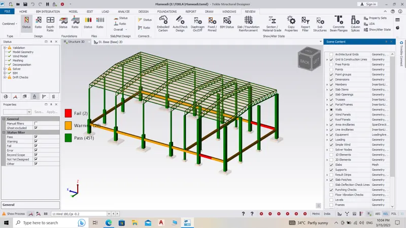
Different entity types have different levels of information associated with them. You can select how much of this information is displayed in each of the different scene views and view regimes. Scene content selections are saved independently with each scene view.
In this project, in scene content window all members, loadings are on so we can see everything in working space.
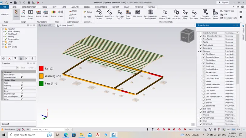
Now, I turn off the steel column, truss, and concrete column in the scene content and they get hidden in the view.
- Create two scene views

- Loading drop list- How to access
- Open project
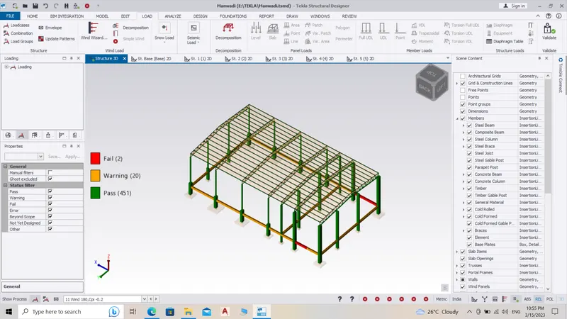
- Click on loads in the menu.
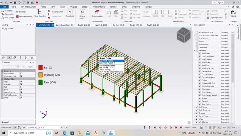
- Then click on combinations.
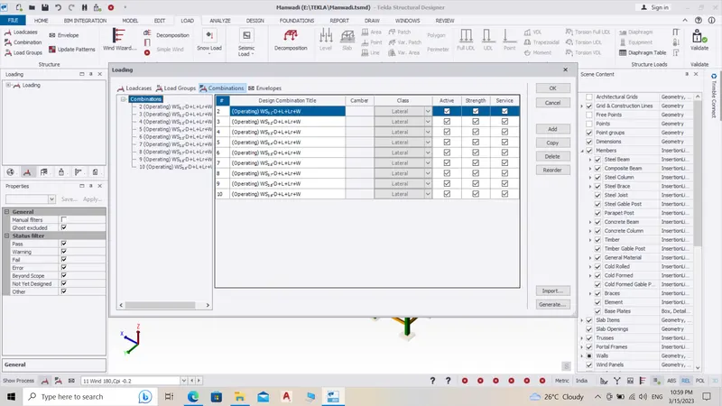
- Properties windows – how to access and usage
- Open project
- Then click on WINDOW in menu,
- now you can see a property window on left of the screen.
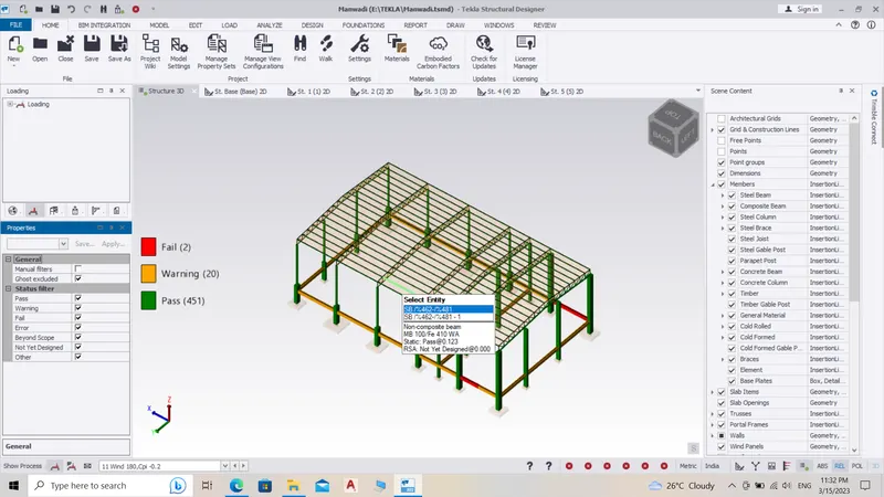
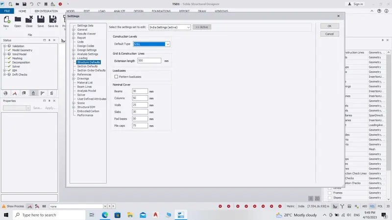
2. Create a new file in TSD and set up the settings for a steel building to have member grade FE410 and concrete grade of M30 as per IS codes. The covers for the members to be as per the following input: -
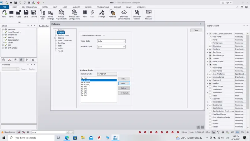
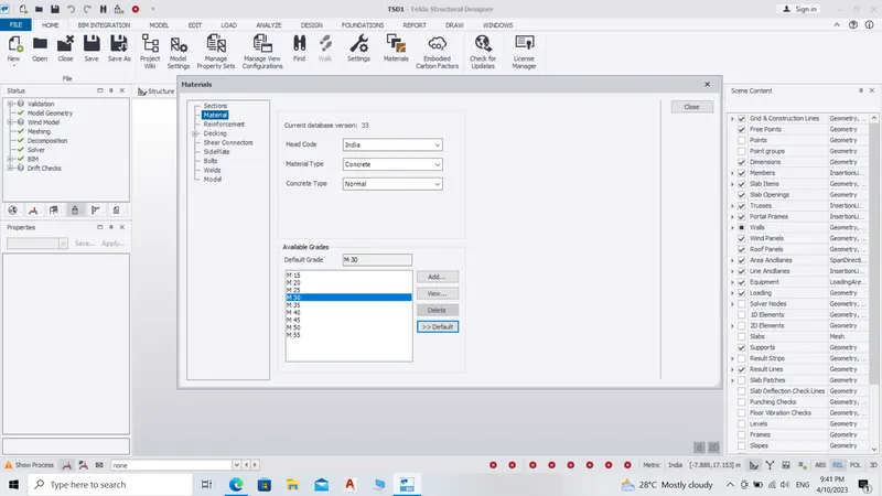
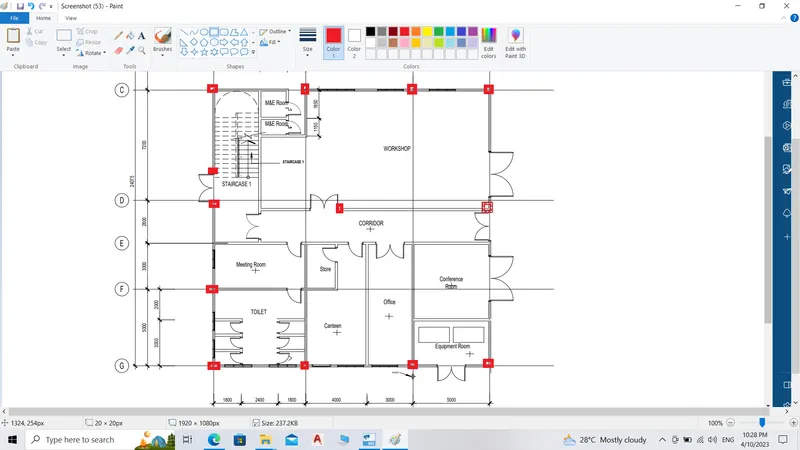
3. With reference to the input drawing as per Attachment 1, 1.1, and 1.2 and study the steel building plan and summarize your understanding of the plan. Based on your study assume and explain the location of columns and beam and develop a hand sketch for each plan
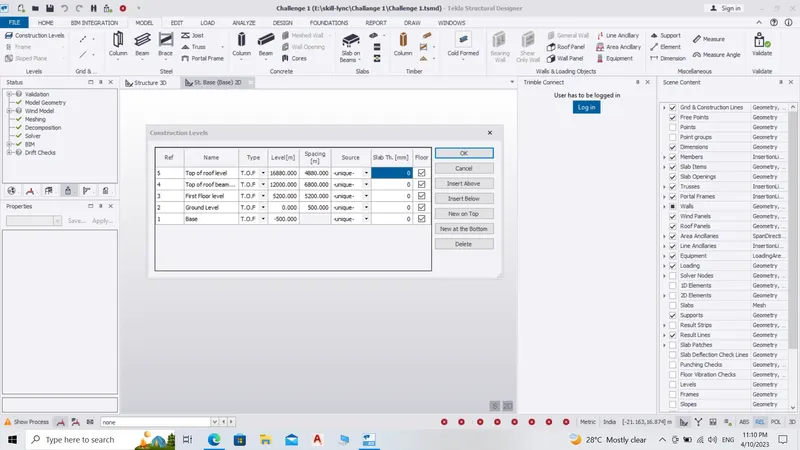
4. Model grid lines and construction levels as per Attachment 1. 1.1 and 1.2. All dimensions are in mm
Construction Lines.
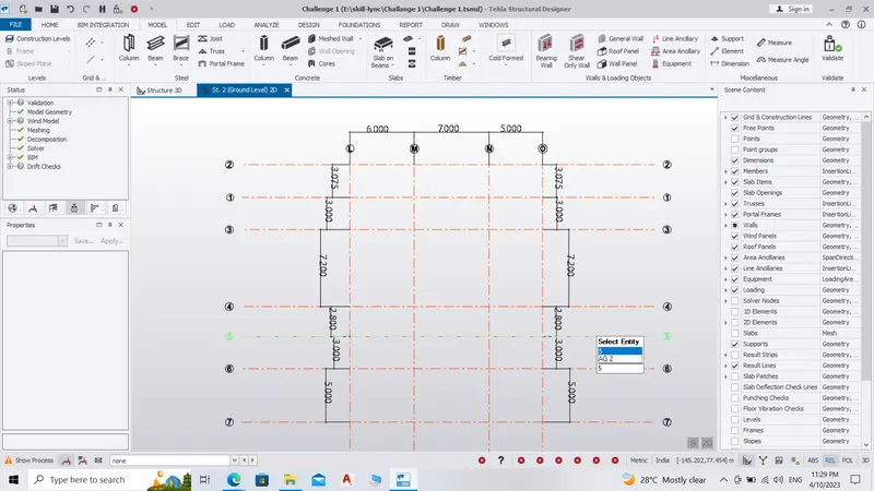
Grid lines.
Thank you.