To plan a structural layout and to create grids using TSD
1.Aim:
To get to know and summarize the user interface in Tekla Structural Designer (TSD).
Procedure:
- Open the TEKLA software.
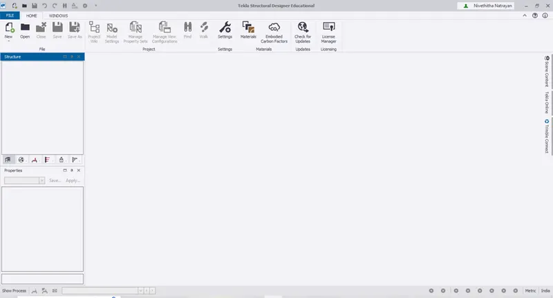
- Go to file -> new
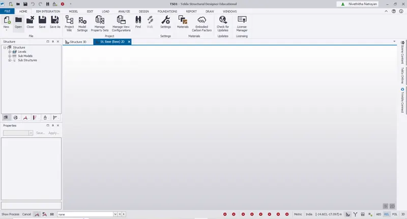
- Varies items in the TSD interface is discussed below:
- Project Workspace:
- The Project Workspaceis a central location of organizing the entire model into a hierarchical structure. It is highlighted below.
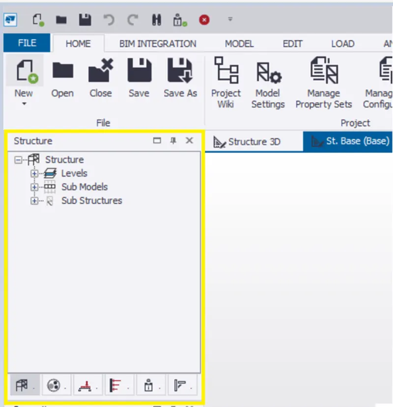
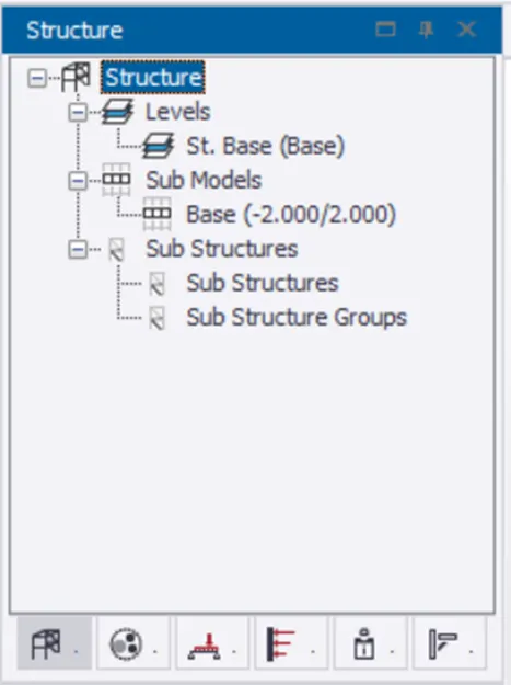
- It gives the information about the levels, sub models, sub structure, etc.
- Expand with the help of right click to the view the select the options.
- Scene Content:
- The Scene Contentsidebar on the right side of the screen is used to control the displayed content in the 2D and 3D Scene Views.
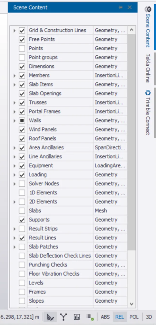
- Click and drag to the left to expand the view.
- Click the arrow at the sides of the categories to view the drop-down sub-categories
- Check boxes are available to enable and disable the respective entities.
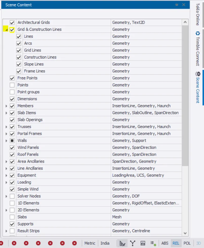
- To create two scene views:
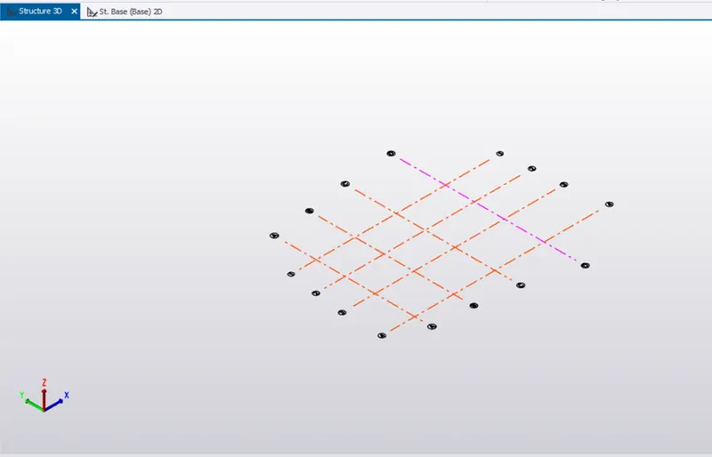
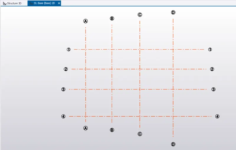
- 2D views, 3D views and solver views, of the model, sub models, frames, construction levels and individual members can be displayed in tabbed windows.
- For example, select grid lines in the ribbon tool draw and draw horizontal and vertical grid lines.
- Select structure 3D to view 3D
- Select St.Base to view 2D.
- Loading drop list:
- The Loadinglist is permanently docked at the bottom edge of the main window.
- It helps for selecting a specific load case or load combination to the structure to add loads.
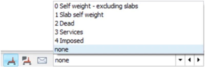
- The above listed loads are default in the drop down list.
- Properties windows:
- The Propertieswindow facilitates the input, review and editing of model properties.
The Properties window is used to:
- input data when a command is run from a toolbar.
- review or edit existing properties when individual or multiple items are selected in the active scene view.
- review or edit properties when a branch of the Propertieswindow is selected.
The properties displayed vary according to the selection. You can edit all of the properties, unless they are greyed out.
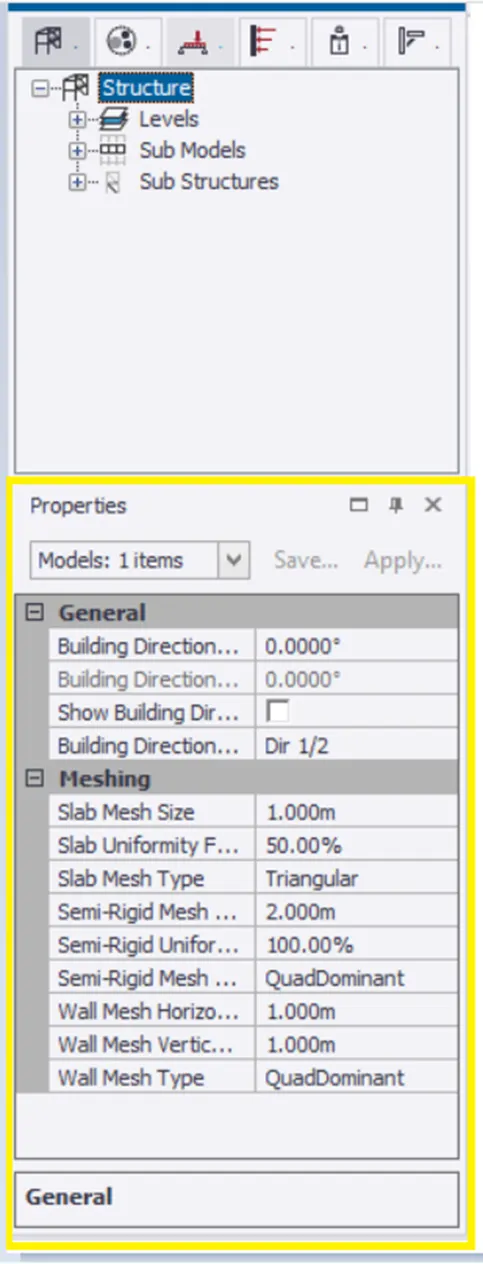
- For instance, if the particular entity is selected in workspace the respective property will be displayed in the property window, which can be edited.
Result:
Hence the above-mentioned items are summarized.
2.Aim:
To Create a new file in TSD and set up the settings for a steel building to have member grade FE410 and concrete grade of M30 as per IS codes. The covers for the members to be as per the following input: -
|
MEMBERS |
IN CONTACT WITH GROUND |
ABOVE GROUND |
|
Column |
50mm |
40mm |
|
Slab |
30mm |
25mm |
|
Pile cap |
75mm |
|
|
Foundation |
50mm |
Procedure:
- Open TEKLA software.
- Go to file -> New.
- In the Ribbon tab select Materials icon.
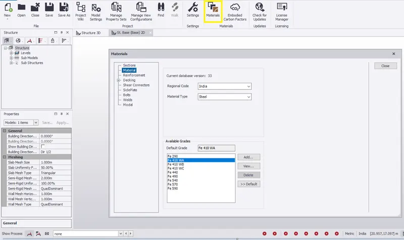
- Under Material option select the material type- steel as FE410 with the above settings.
- Change the material type as concrete and select M30.
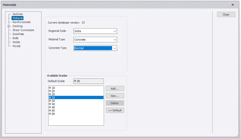
- Click close.
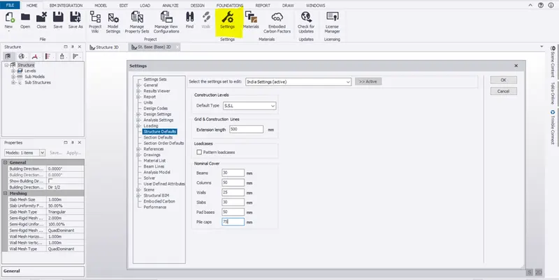
- Go to Home tab -> settings icon
- Select structural default in the option and give the cover value for the members under Default type as S.S.L
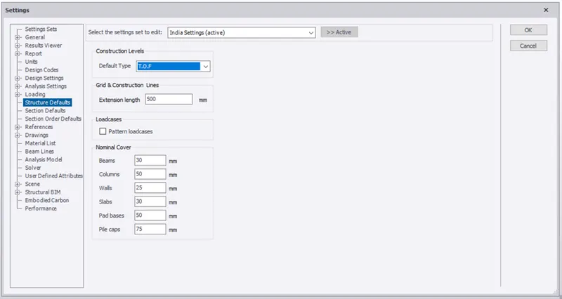
- Change the Default type as T.O.F to view the value.
- Click ok
Result:
Hence the set up for the steel building is done as mentioned above.
- Aim:
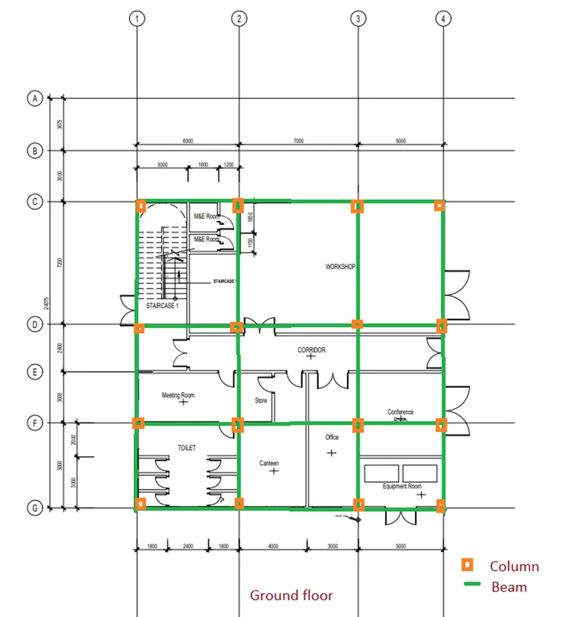
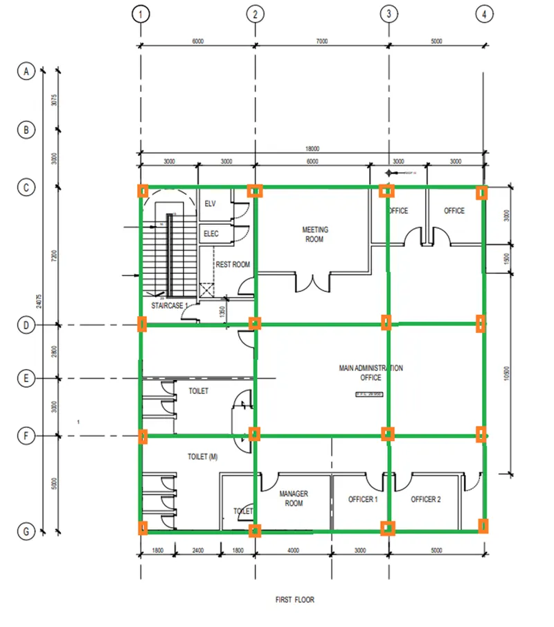
To create the location of columns and beams and develop a hand sketch for each plan with reference to the input drawing as per Attachment 1, 1.1, and 1.2 of the steel building plans.
Procedure:
- Open given attachment 1, 1.1, and 1.2.
- Copy it to the paint to draw the rough sketch of location of the beams and columns.
- Create the beams in straight path for the load transfer from one end to the another end without any disconnection.
- Have columns at the 4 corners and the intersection of the beams for the support as shown below.
- Attachment 1:
- Attachment 1.1:
- Attachment 1.2:
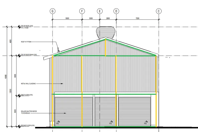
Result:
- The rough sketch of beams and columns are shown in the above plan and elevation view.
4.Aim:
To model grid lines and construction levels as per Attachment 1. 1.1 and 1.2.
Procedure:
- Open the Tekla software interface.
- Under Home tab select Settings icon.
- In the settings dialog box select units as metric
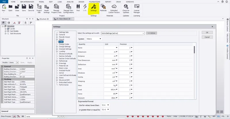
- Click ok.
- To Create construction levels:
- Go to Model tab -> Construction level
- Select insert above to add levels
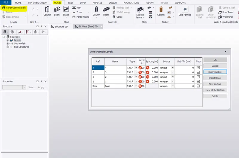
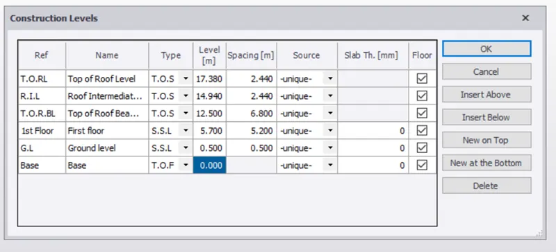
- Edit the names and heights as mentioned in the plan and elevation as shown below.
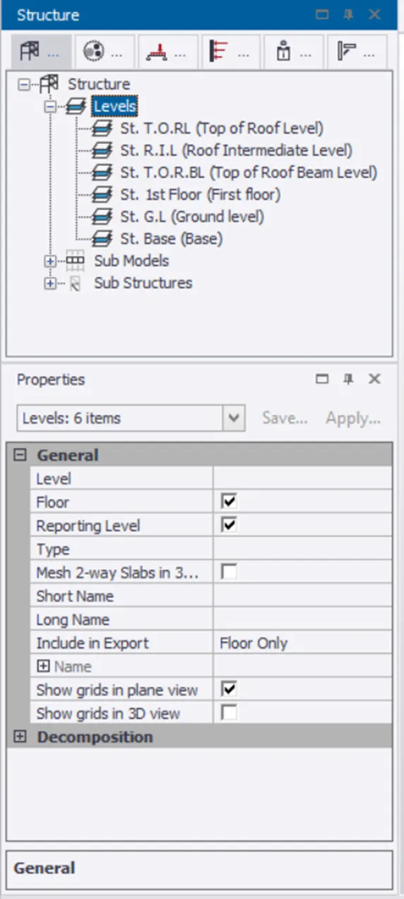
- To create Grid lines:
- Go to Grid line icon and draw the first vertical grid 1 with the following settings in the property window.
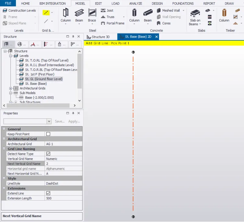
- Select Parallel quick option under grids and give distance after clicking the reference grid line 1.
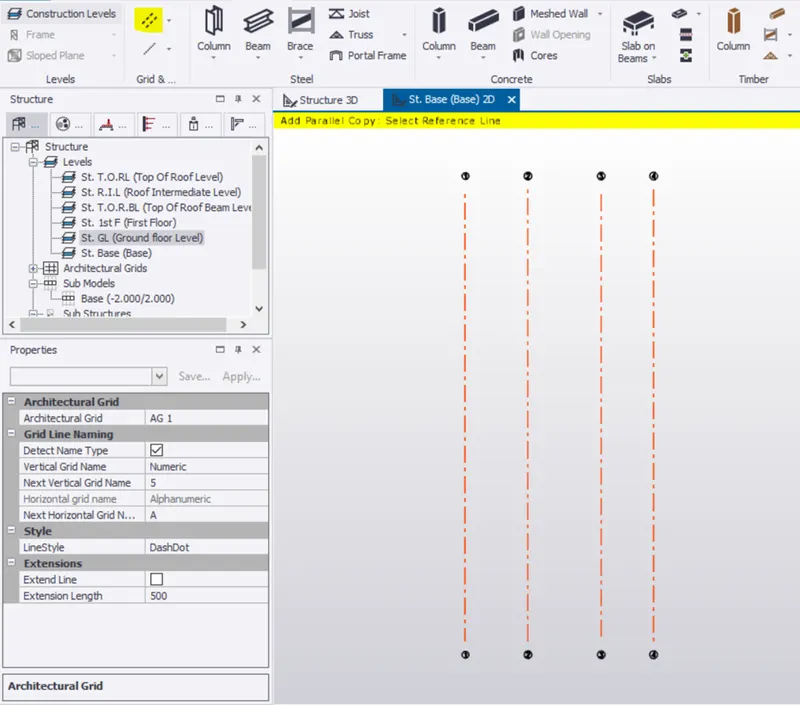
- Like wise create the horizontal grid line A as reference line and create the rest of the grid lines as per the drawings.
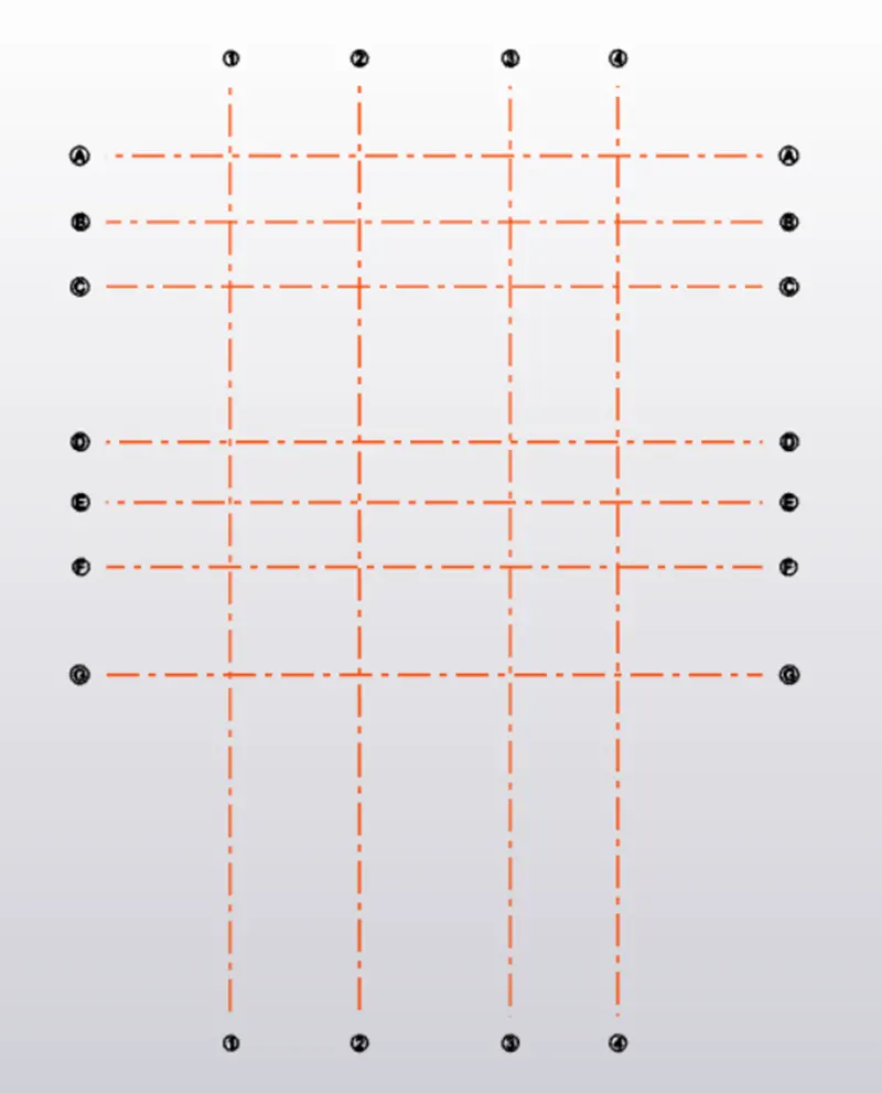
- Click Dimension icon to create the dimension between two lines as shown below.
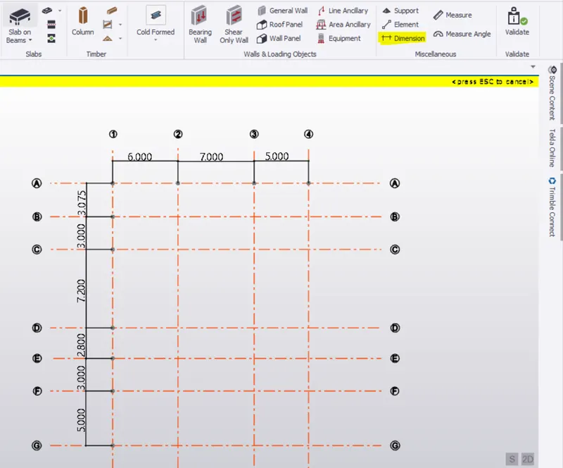
Result:
Hence the grids are created as per the drawings for the steel building.