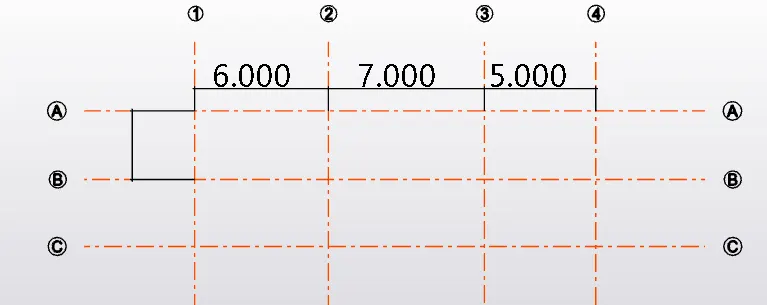
To plan a structural layout and to create grids using TSD
1. Summarize the user interface in TSD with the for the following items: -
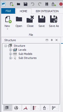
- Project Workspace – How to access and usage
AIM :
To access project workspace in Tekla structural designer
Procedure:
Open Tekla structural designer
Below the ribbon button , the project workspace is available to the left of the screen
It provides information regarding model and loadings
Result:
- Scene Content – Demonstrate the use of scene content
AIM :
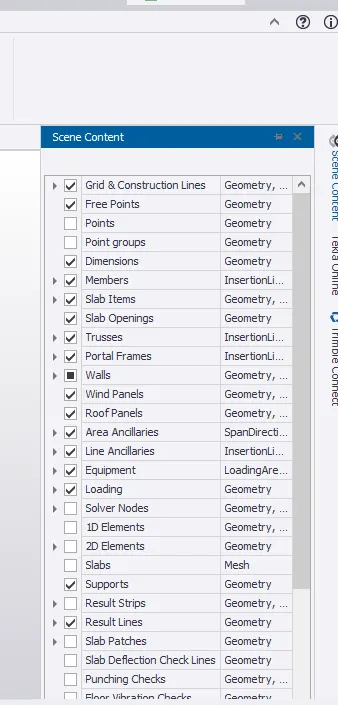
To Demonstrate the use of scene content
Procedure:
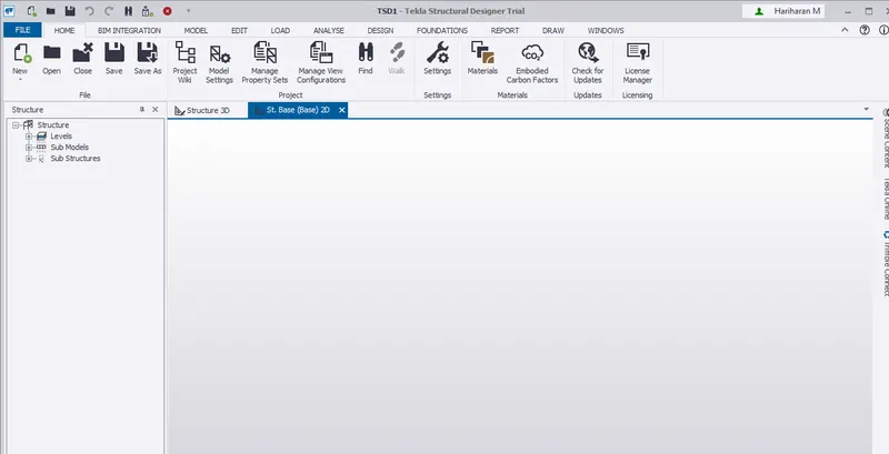
The plain space in the middle of the screen is said to be screen view
it is used to view the Model in 2D or 3D
Result:
- Create two scene views
AIM:
To create the two scene views
Procedure :
In the tekla structural designer, click on home.
The plain space in the middle of the screen is called scene view
The scene view is used to view the model in 2D or 3D.
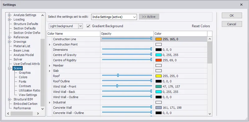
Under the ribbon tab click on settings.
Click on scene.
Result:
- Loading drop list- How to access
Aim:
To access loading drop list.
Procedure:
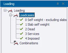
Open Tekla and click home.
Click on the loading list available at the left bottom.
- Properties windows – how to access and usage
Aim:
To access properties windows
Procedure:
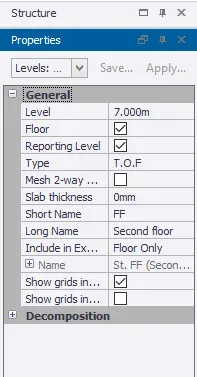
Open TSD and select home.
Properties windows is available on the left side
2. Create a new file in TSD and set up the settings for a steel building to have member grade FE410 and concrete grade of M30 as per IS codes. The covers for the members to be as per the following input: -
MEMBERS | IN CONTACT WITH GROUND | ABOVE GROUND |
Column | 50mm | 40mm |
Slab | 30mm | 25mm |
Pile cap | 75mm | |
Foundation | 50mm |
Aim:
To create a new tekla structural designer and set up settings for steel buildings.
Procedure:
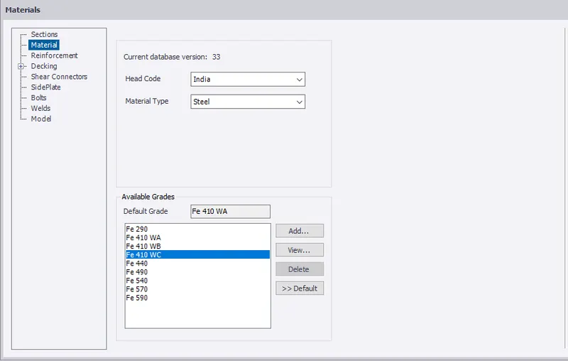
Click on Materials from ribbon tab.
Select steel from the material type.
Select Fe 410 wc and select default.
Click on Materials from ribbon tab.
Select concrete from the material type.
Select M30 and select default.
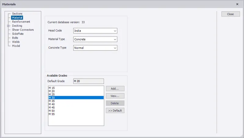 Click on manage property sets and select new.
Click on column and enter the cover as 50mm for in contact with the ground and 40mm above the ground.
Click on new and select cast in place concrete slab.
Enter the cover as 30mm for in contact with the ground and 25mm above the ground.
Click on new and select slab.
Enter the cover as 30mm for in contact with the ground and 25mm above the ground.
Click on new and select pile cap.
Enter the cover as 75mm.
Click on new and select pad base.
Enter the cover as 50mm.
3. With reference to the input drawing as per Attachment 1, 1.1, and 1.2 and study the steel building plan and summarize your understanding of the plan. Based on your study assume and explain the location of columns and beam and develop a hand sketch for each plan
Aim:
To develop hand sketch of drawing.
Procedure:
Open MS paint and start drawing.
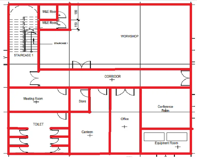
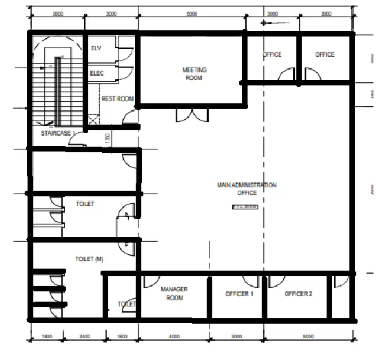
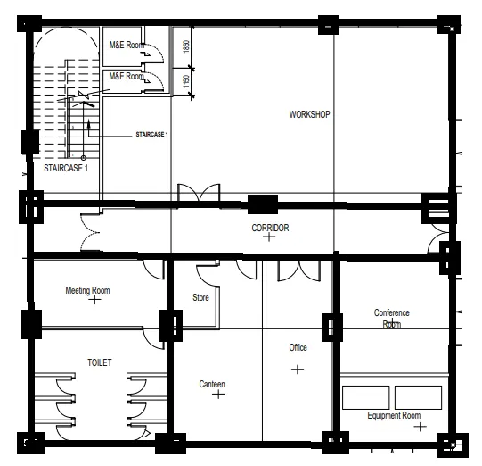
4. Model grid lines and construction levels as per Attachment 1. 1.1 and 1.2. All dimensions are in mm
- The base level to be 500mm below ground level.
Aim:
To model grid line and construction line using tekla structural designer.
Procedure:
Open new file in Tekla structural designer.
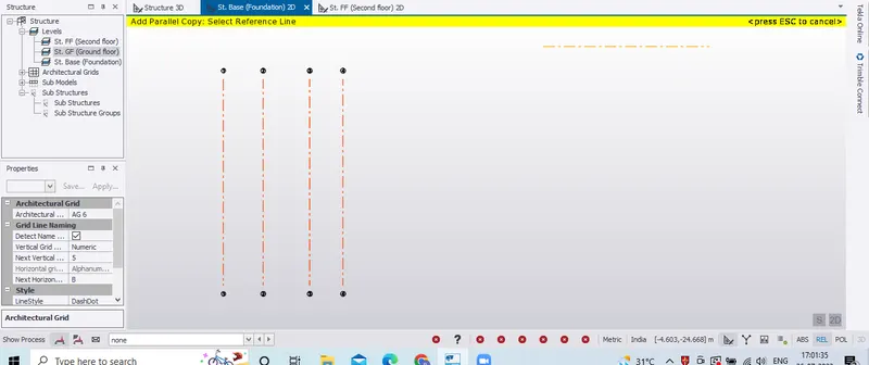
Click model and select grid from the ribbon tab.
In the property tab, enter the vertical grid as numeric and horizontal grid as alphanumeric
Click on starting point in the scene.
Enter the end point.

Click on grid and select quick parallel.
Select the reference line and enter the required distance.
Similarly enter the other grid line distance with respect to the reference line
Similarly go the grid option from the ribbon tab.
Enter your starting point and ending point in the horizontal direction.
Click on grid and select quick parallel.
Select the reference line and enter the required distance.
Similarly enter the other grid line distance with respect to the reference line
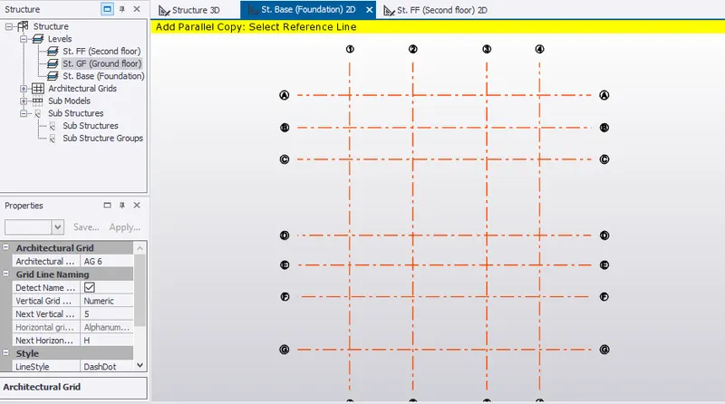
Select dimension from the right top corner of ribbon tab.
Select the starting point and ending point of line of whose dimesions has to be shown.