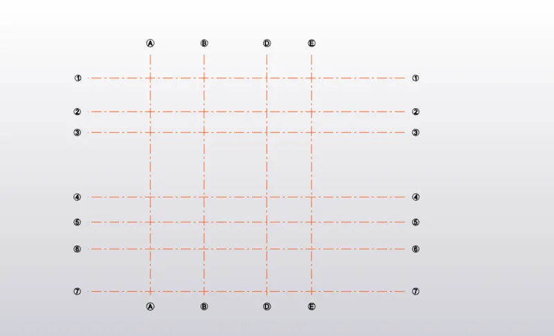
To plan a structural layout and to create grids using TSD
1. Aim: Summarize the user interface in TSD with the following items:-
- Project Workspace – How to access and usage
- Scene Content – Demonstrate the use of scene content
- Create two scene views
- Loading drop list- How to access
- Properties windows – how to access and usage
Procedure:
1. Project Workspace:
- Open Tekla structural design software and click on the new model.
- Now project workspace is visible.
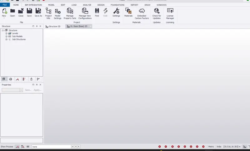
2. Scene Content – Demonstrate the use of scene content
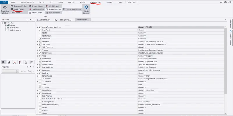
- Now click on the screen content option on the left side of the screen or go to the windows tab and select the screen content.
- Now we can enable or disable the elements
3. Create two scene views:
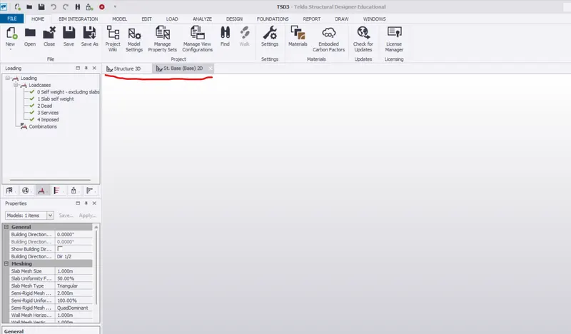
- While creating the new file itself, the software creates 2 default views like 2D and 3D
4. Loading drop list:
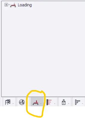
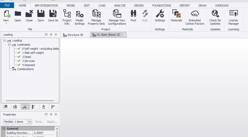
- On the left side of the workspace click on the loading symbol and click on +icon to drop list of loads
5. Properties windows:
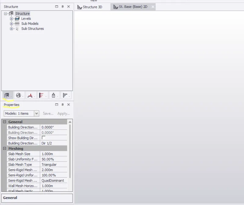
- Select the property window at the left side and the properties will be visible
2. Aim:
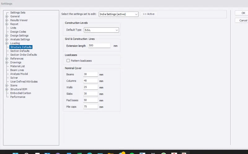
Create a new file in TSD and set up the settings for a steel building to have member grade FE410 and concrete grade of M30 as per IS codes. The covers for the members to be as per the following input: -
|
MEMBERS |
IN CONTACT WITH GROUND |
ABOVE GROUND |
|
Column |
50mm |
40mm |
|
Slab |
30mm |
25mm |
|
Pile cap |
75mm |
Procedure:
- Open Tekla structural design software and click on the new model.
- Now project workspace is visible.
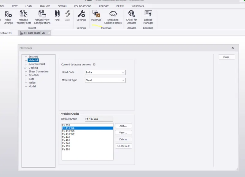
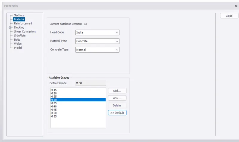
- Go to the material dialogue box and select the materials. now under the material type drop-down list select steel and select the desired steel as Fe410
- And also select concrete material of grade as M30
- In order to change the cover thickness, click on the setting option in the ribbon tab and then under the loading section and select the structure default.
- Select SSL and apply the cover values.
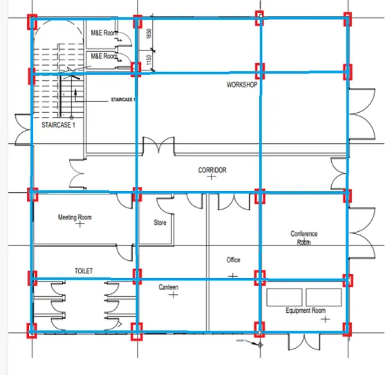
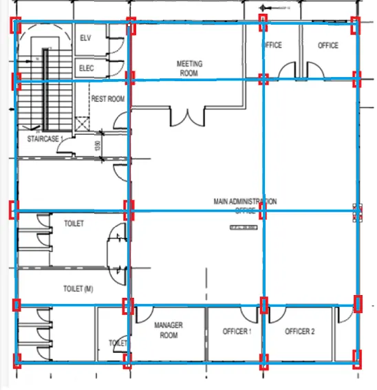
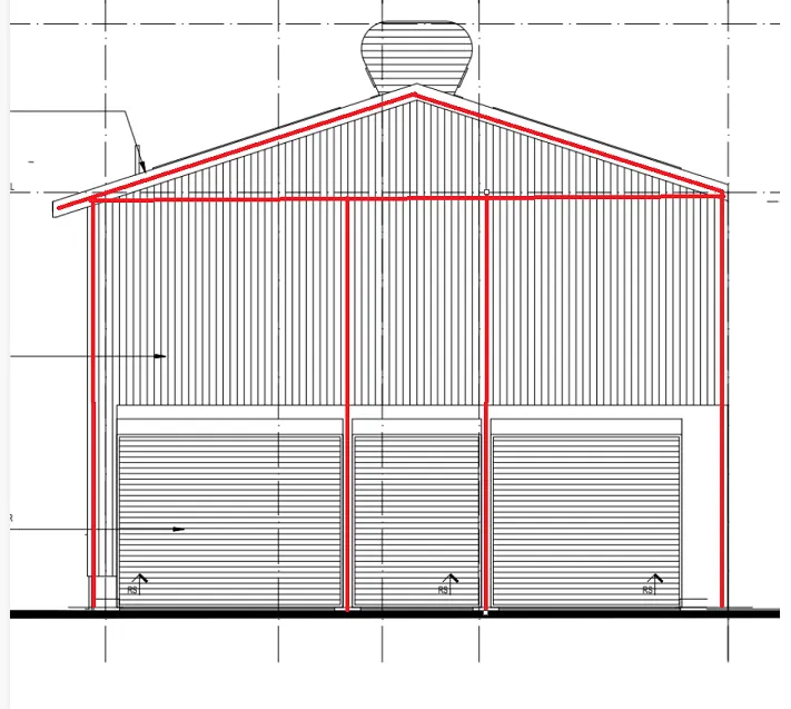
3. Aim: With reference to the input drawing as per Attachment 1, 1.1, and 1.2 study the steel building plan and summarize your understanding of the plan. Based on your study assume and explain the location of columns and beams and develop a hand sketch for each plan.
Procedure:
- Open Tekla structural design software and click on the new model.
- Now project workspace is visible.
- Position of columns and beams
- Ground floor
- First floor
- Elevation
4. Aim: Model grid lines and construction levels as per Attachment 1. 1.1 and 1.2. All dimensions are in mm. The base level to be 500mm below ground level.
Procedure:
- Open Tekla structural design software and click on the new model.
- Now project workspace is visible.
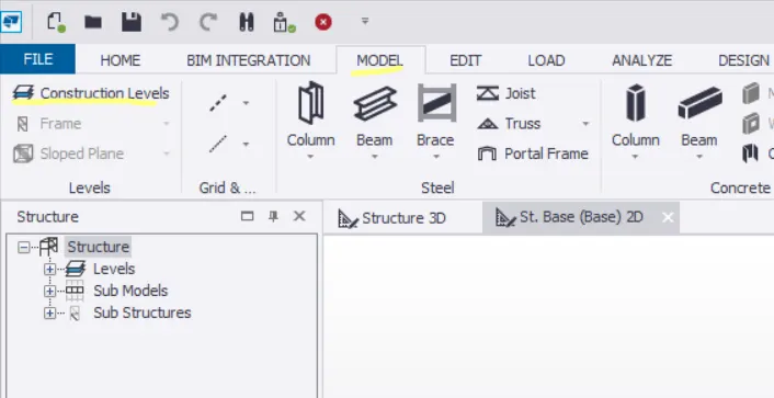
- Go to the model toolbar, select construction levels, and open the construction dialogue box.
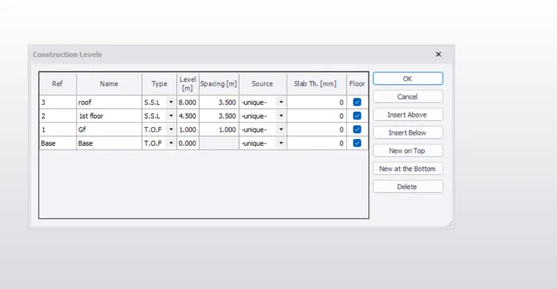
- Now a dialogue box will appear, name each level, and assign the heights
- Now using the grid line and parallel grid line draw the vertical and horizontal lines by the given dimensions.