To model columns for industrial steel structure using TSD
Questions. 1. Create column properties for different types of pedestal members and model in the grids created as per the assignment 1.
2. Create column properties for steel columns and model columns in the grid created as per assignment 1.
3. Create beam properties and model primary and secondary beams on the ground floor.
Answers.
1. Create column properties for different types of pedestal members and model in the grids created as per the assignment 1.
Solution:
AIM: To create column properties for the different types of the pedestal members and to model in the grids that we created in the previous assignment.
PROCEDURE:
- So the very first step in creating the column properties for the different types of the pedestal members is to open the TEKLA DESIGNER SOFTWARE.
- After opening the software go to the File ribbon,in that ribbon there will be a drop-down list and in that list there will be an option called OPEN,just click on that option.
- After that there will be another dialouge box named as the OPEN, in that dialouge box search for the file of the previous assignment.
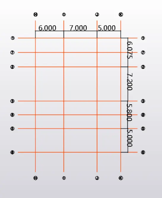
- Click on the selected file and then press OK,now the file of the previous assignment opens.
- Now after opening the previous assignment,go to the Home menu and in that ribbon there will be an option called Manage Property Sets just click on that option just as shown in the below given image:
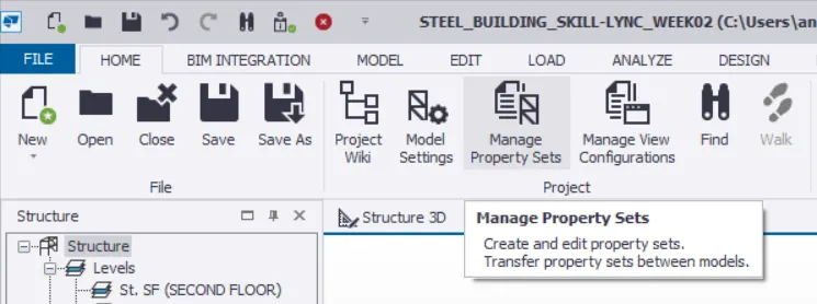
- After this there will be a dialouge box named as the Manage Propert Sets.
- And in that dialouge box on the right hand side there will be an option called New just click on that option after that there will be another drop-down list and in that list there will be another option called Members just click on that after that there will be another drop-down list and in that list there will be another option called Concrete Column just click on that option just as shown in the below given image:
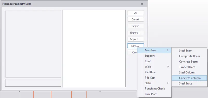
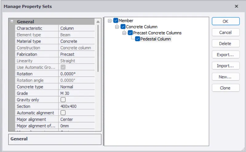
- After this the properties for the Concrete column has been created just as shown in the below given image:
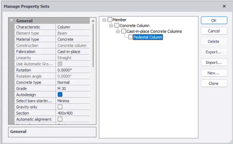
- And now there will be options on the left-hand side,just fill the information just as shown in the below given image:
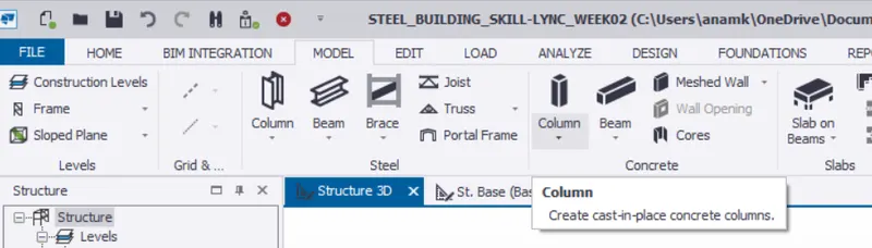
- Now after that go to the Model option and in that option there will be an option named as the Column just click on that option just as shown in the below given image:
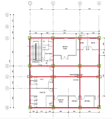
- And after draw the column according to the plan just as the shown in the below given image:
GROUND FLOOR PLAN WITH COLUMN AND BEAM POSITION:
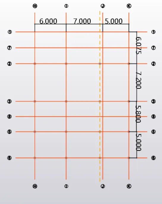
PEDESTAL COLUMN IN TSD SOFTWARE(2D-VIEW):
3D-VIEW:
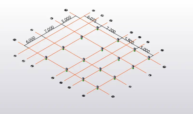
2. Create column properties for steel columns and model columns in the grid created as per assignment 1.
Solution:
AIM: To create the column properties for the steel columns and model the columns in the grid created as per the pervious assignment.
PROCEDURE:
To create the column properties for the steel columns:
- Now first we will be creating the column properties for the steel columns,and in order to do that first go to the Home tab click on that then there will be another option called Manage Property Sets just click on that option just as shown in the below given image:
- And after that there will be another dialouge box named as the Manage Property Sets and in that dialouge box at the right hand side of that box there is an option called New just click on that option after that there will be another drop-down list and in that list there will be an option Members just click on that option after that there will be another drop-down list and in that list there will be another option called Steel Column just click on that option just as shown in the below given image:
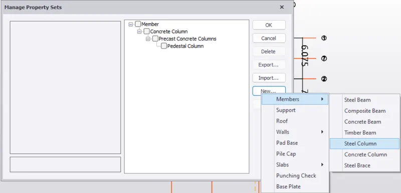
- And now at the left-side of the dialouge box there is an option called Section just click on that option.
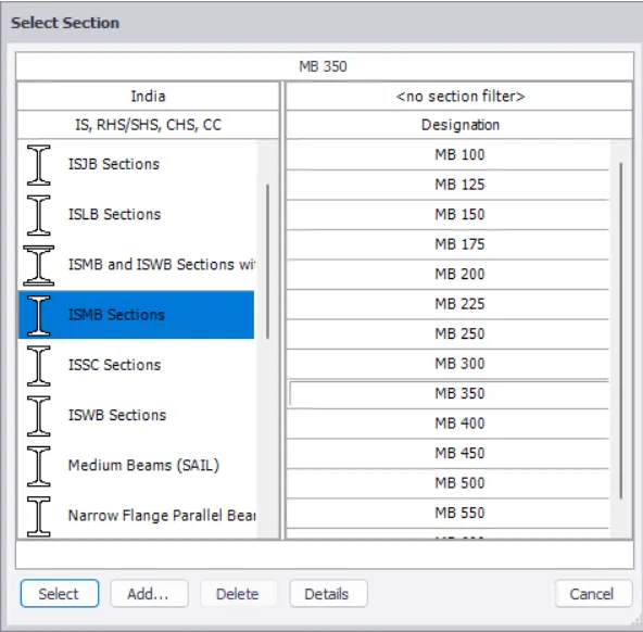
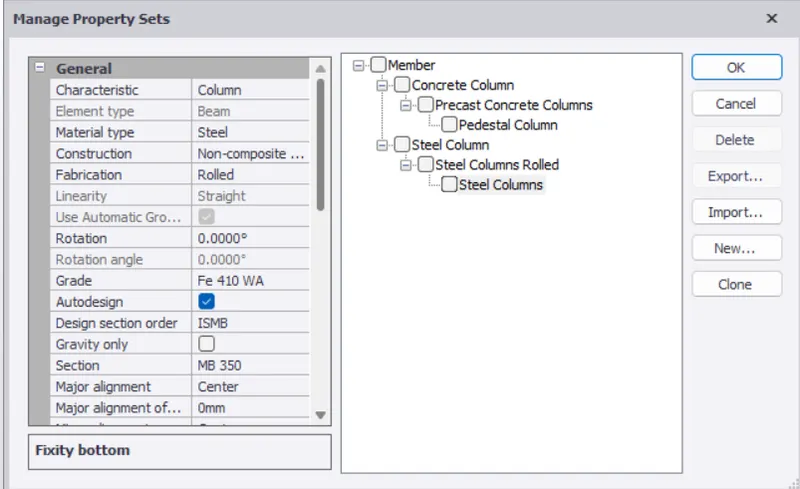
- After that select the section as ISMB 350 just as shown in the below given image:
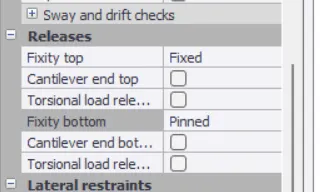
- Now we have to assign the releases,in that there will be option Fixity top as Fixed and Fixity bottom as Pinned just as shown in the below given image:
- After that there will be another options just fill out the all necessary details just as shown in the below given image:
Model the columns in the grids:
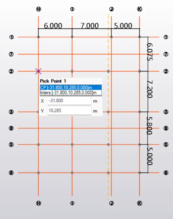
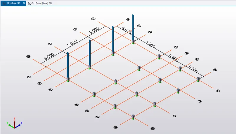
- Now we will be modelling the columns in the grid 2 of the previous assignment just as shown in the below given image:
2D-VIEW:
3D-VIEW:
- Now we will be assigning C2 columns with the rotation of 90 degree in the remaining grids.
- And in order to do that,again go the Manage Property Sets option present in the Home tab as shown in the below given image:
- And in the left hand side of the dialouge box there will be an option called Clone just click on the option and clone the properties just change the rotation as 90 degree just as shown in the below given image:
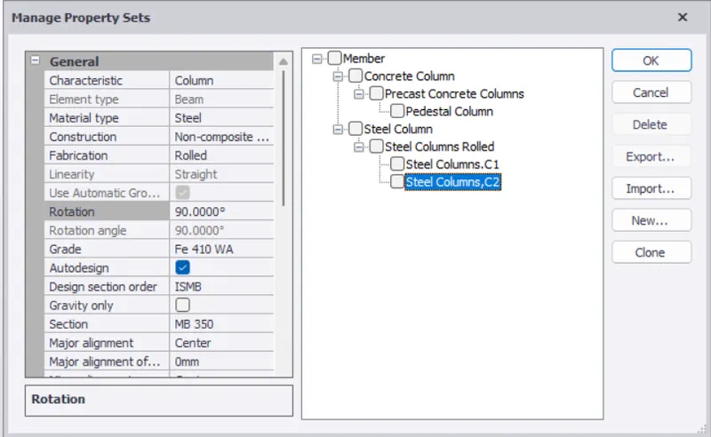
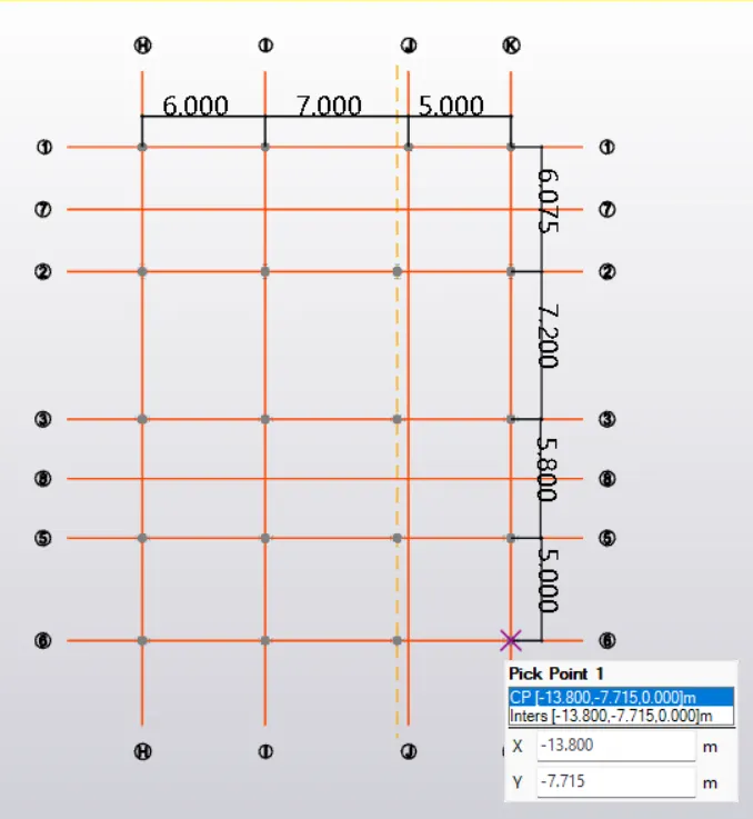
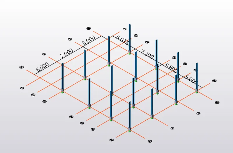
- Now assign the C2 steel columns in the remaining grids just as shown in the below given images:
2D-View:
3D-View:
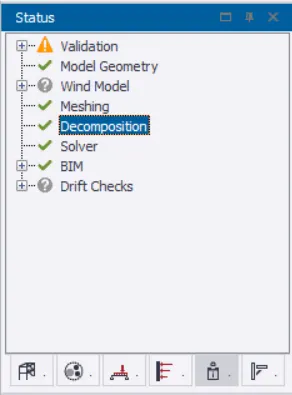
- Now we will be doing the validation/checking the model.
- And in order to validate the model just go to the model tab and there at the right corner there will be an option called Validate just click on that option just as shown in the below given image:

- Validation is done as we can see in the below given image:
3. Create beam properties and model primary and secondary beams on the ground floor.
Solution:
AIM: To create the beam properties and model the primary and secondary beams on the ground floor in the TEKLA STRUCTURAL DESIGNER.
PROCEDURE:
- Now we will be creating the beam properties first,and in order to do that first go to the Home tab click on that then there will be another option called Manage Property Sets just click on that option just as shown in the below given image:
-
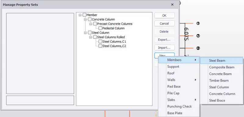
- And after that there will be another dialouge box named as the Manage Property Sets and in that dialouge box at the right hand side of that box there is an option called New just click on that option after that there will be another drop-down list and in that list there will be an option Members just click on that option after that there will be another drop-down list and in that list there will be another option called Steel Beams just click on that option just as shown in the below given image:
- And now at the left-side of the dialouge box there is an option called Section just click on that option.
- After that select the section as ISMB 350 just as shown in the below given image:
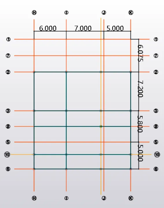
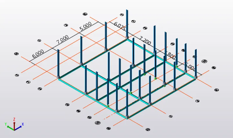
- Now we will be assigning the Primary beams which connects the columns just as shown in the below given image:
PRIMARY BEAMS IN 2D-VIEW:
PRIMARY BEAMS IN 3D-VIEW:
SECONDARY BEAMS:
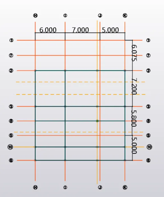
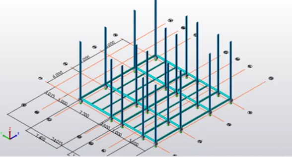
- And now we will be assigning the secondary beams, and in order to assign the secondary beams do the same procedure as the primary beams as shown in the below given image:
SECONDARY BEAMS IN 2D-VIEW:
- For larger span provide ISMB 400 and for another beam provide ISMB 250 just as shown in the below given image:
SECONDARY BEAMS IN 3D-VIEW:
- Now we will be doing the validation/checking the model.
- And in order to validate the model just go to the model tab and there at the right corner there will be an option called Validate just click on that option just as shown in the below given image:
- Validation is done as we can see in the below given image: