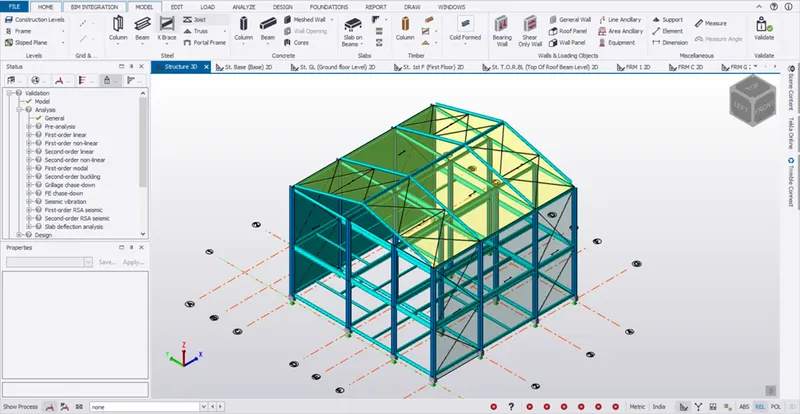
To model beams and bracings for industrial steel structures using TSD
1.Aim:
To create beam properties for First floor and model the beams by using TSD.
Procedure:
- Open the TSD file which was modelled in the earlier challenges.
- In the structure window click first floor.
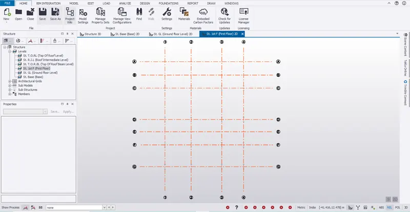
- Click 3D in the status bar to view the 3D view of first floor.
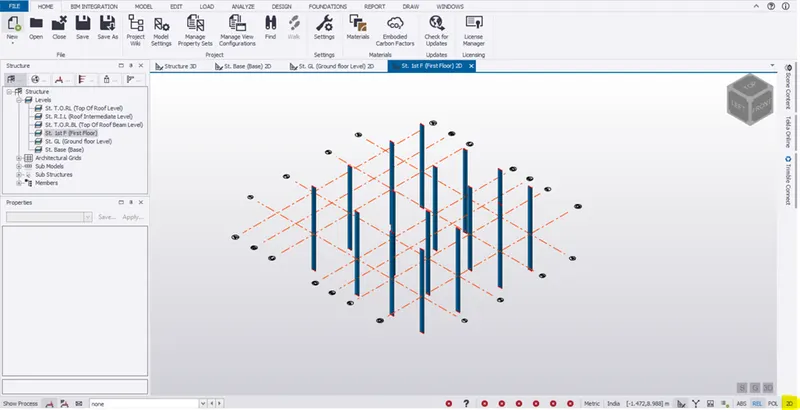
- To create beams in first floor:
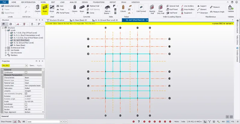
- Create a new beam property for Grid C and D which helps to support crane movement.
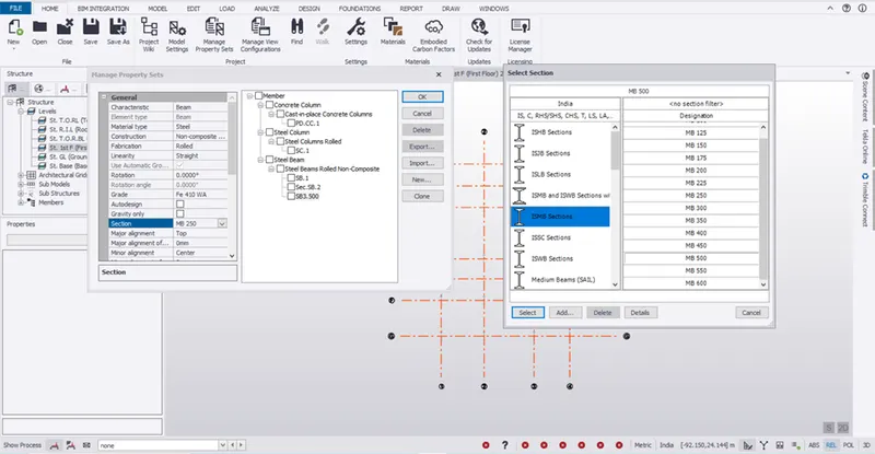
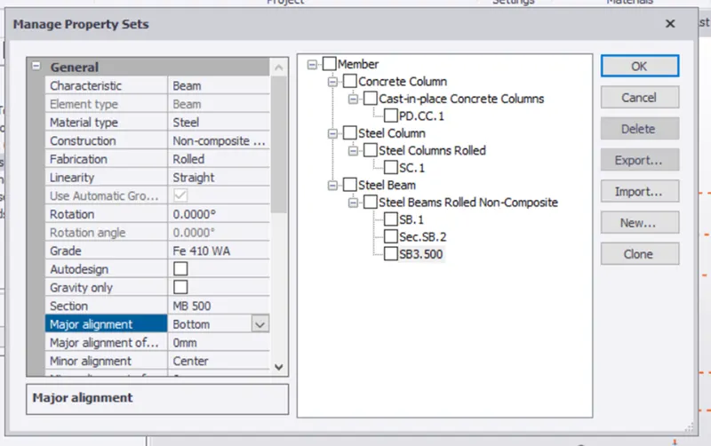
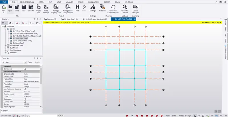
- Go to first floor plan and connect the main beam from column to column with the created property.
- To create secondary beams:
- Go to Ground level and create construction lines for creating secondary beams with the created property.
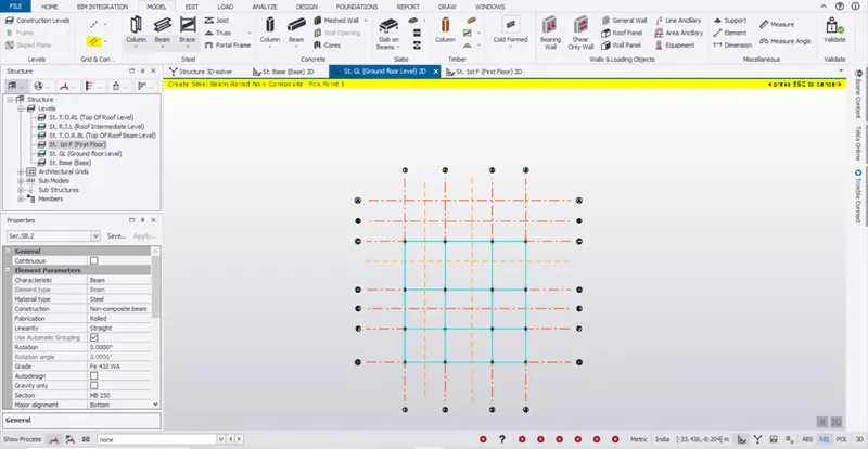
- Create secondary beam as required by referring the floor plan.
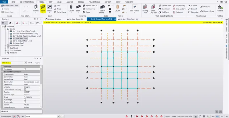
- Go to first floor and follow the above procedure and create construction lines and secondary beams as required.
- Result:
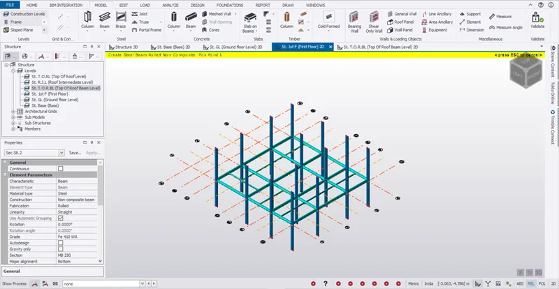
- Click 3D icon in the bottom right corner to view the 3D view of a particular floor.
- Main beam and secondary beams are created in the first floor.
- Aim:
To create rafter beam on second floor as roof and moment frame action in one direction and add bracings at locations as per the design intent
Procedure:
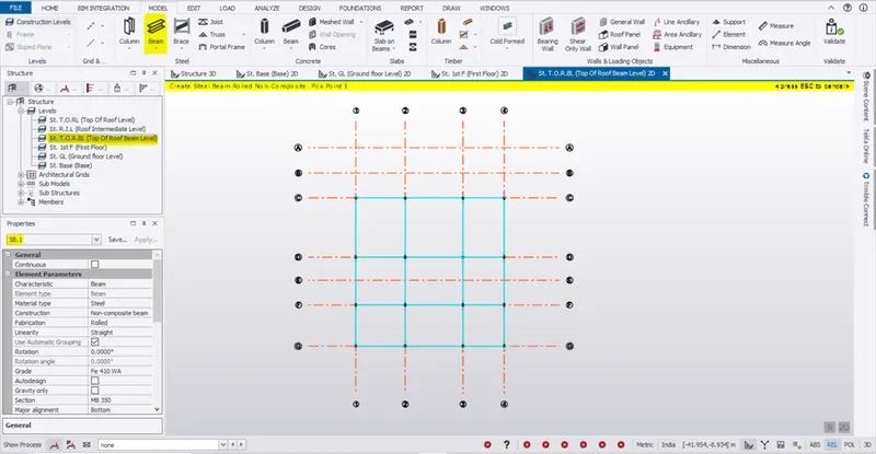
- With above created model, go to Top of roof beam level
- Click Model -> Beam
- Select the beam property as SB1 which is used as main beam in ground level and connect the columns as shown below.
- Creating frames:
- Go to Model -> Frames and pick grinds one by one
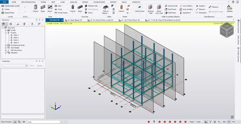
- Similarly create the frame on other direction.
- Expand the frame option in structure window to view the created frames
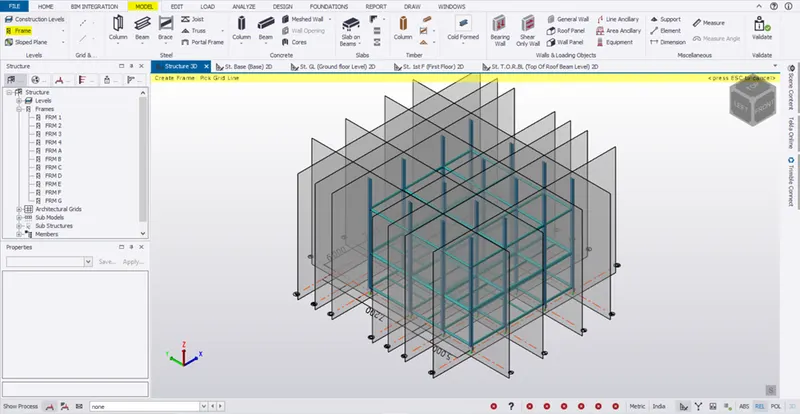
- Creating Roof beam:
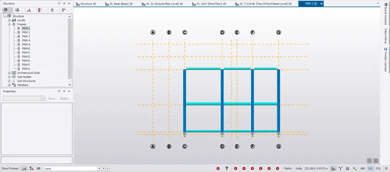
- Go to FRM1 and create construction line at the middle
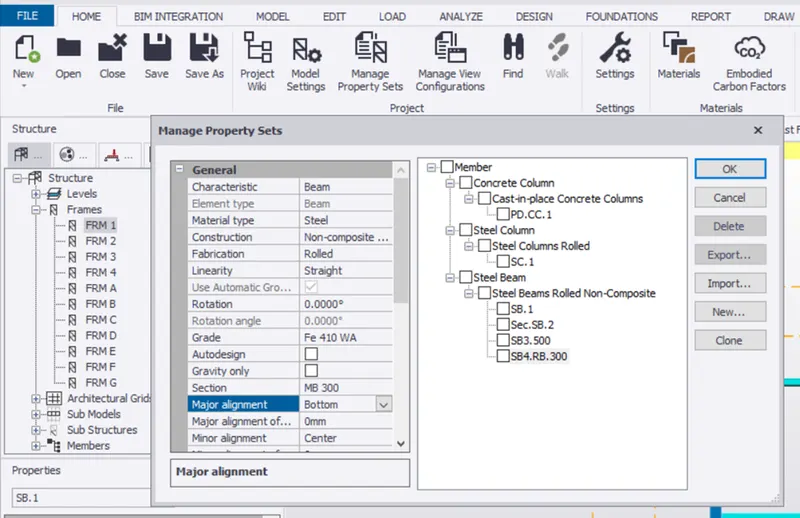
- Go to Home ->Manage property sets. And create beam property for roof beams
- Go to Model -> Beam and select the above created beam as rafter beam and column to the construction line on both sides
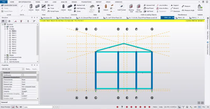
- Select the rafter beams in 3D view and Go to Edit -> Copy
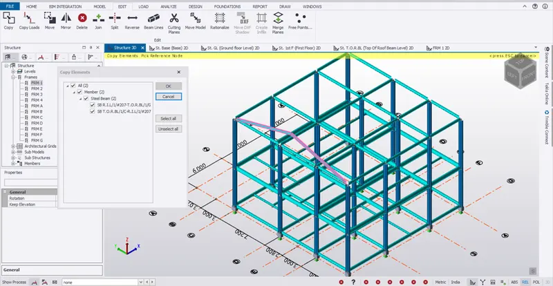
- Pick a reference point and place it to the adjacent columns.
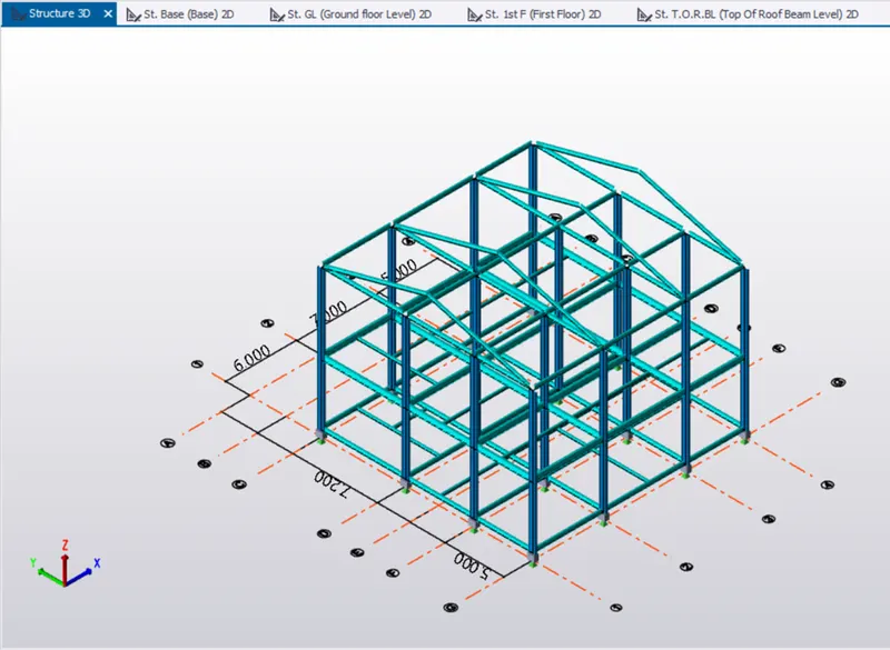
- To have moment release on the rafter frame, double click on the frame and give following settings.
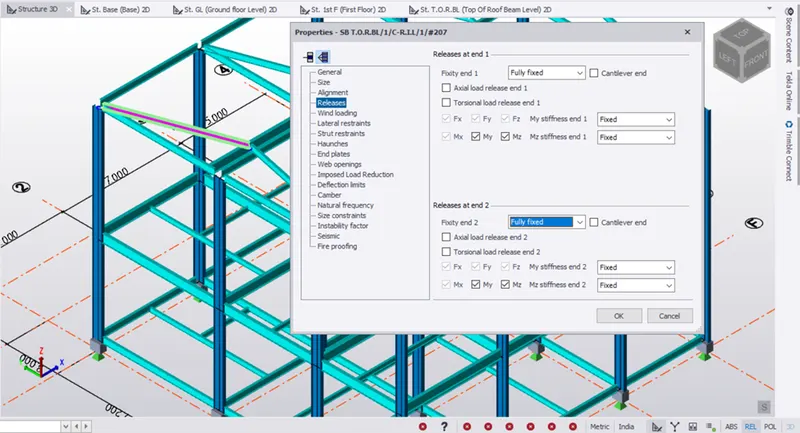
- Click ok and continue the same procedure for all other rafter beams.
- To create bracing:
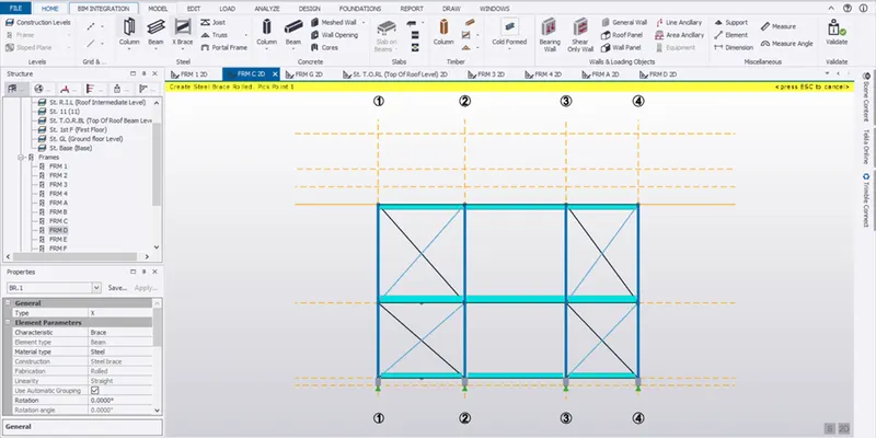
- Select FRM C 2D view
- Go to Home -> Manage property sets -> New -> Members -> Steel bracing and give following settings
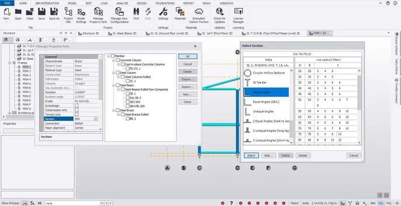
- Go to Model -> X Brace and select the property as BR.1
- Pick corner 4 points to connect the bracing.
- Adjust the major snap level according to the design
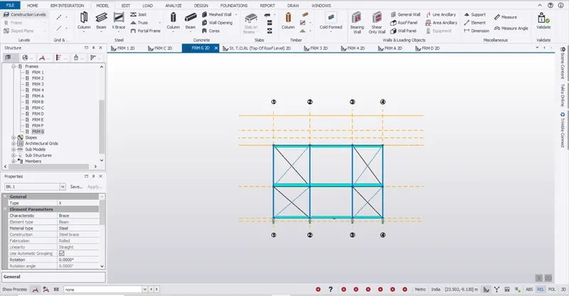
- Similarly, do it on Grid G in FRM G 2D
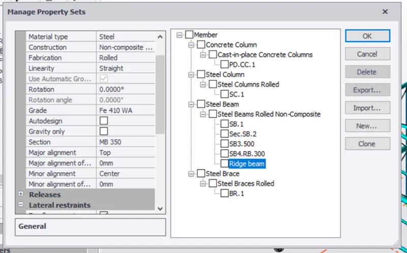
- To create Ridge beam:
- Go to Home -> Manage property sets -> New -> Members -> Steel beam and give following settings
- Go to Home -> Manage property sets -> New -> Members -> Steel bracing and give following settings
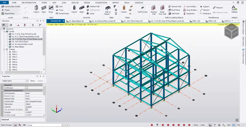
- To create bracing on the roof panel:
- Go to Model -> Brace and pick the center point of the section of roof panel and connect it to the other end of the same section.
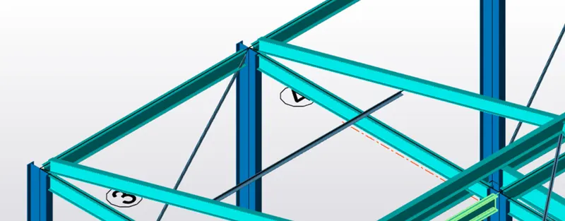
- Then select X Brace and create X brace as shown below.
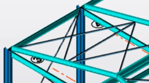
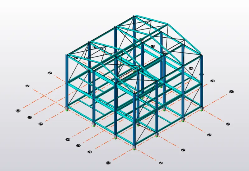
- Repeat it to the other panels
- To create wall panel:
- Go to Model -> wall panel
- Select 5 corner points between columns.
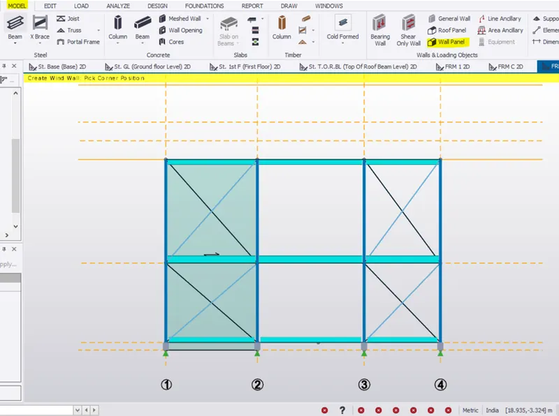
- Repeat the same procedure to the other area to apply wall panel.
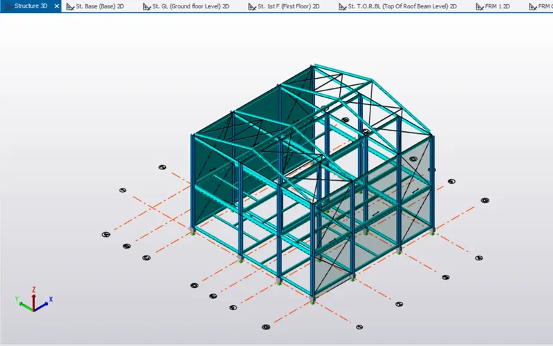
- To model Roof panel:
- Go to Model -> Roof panel.
- In 3D view click the corner points and create roof panel on the roof.
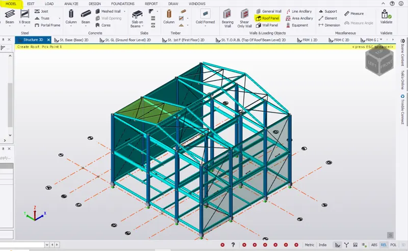
- Repeat it throughout the roof.
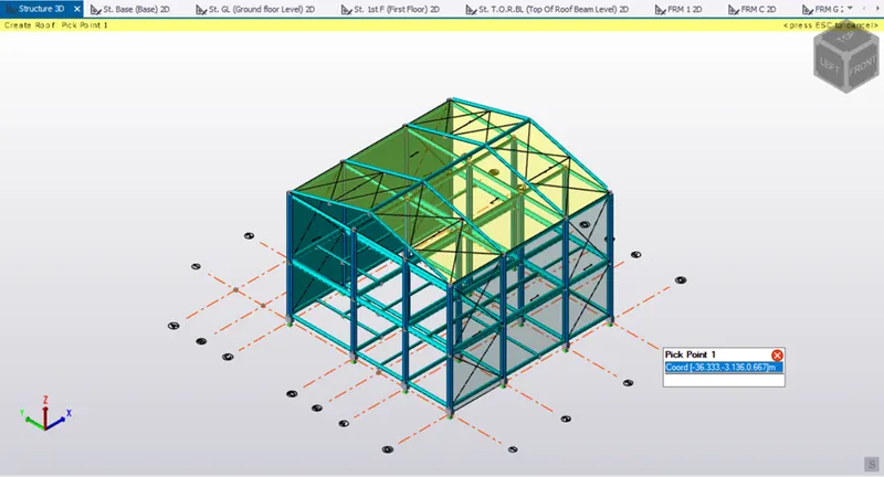
- Result:
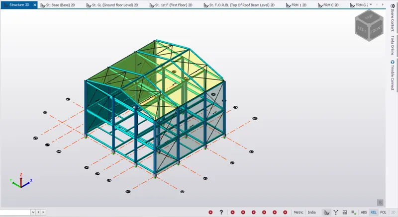
- Hence the beams, bracings, wall panel, roof panel are all have been model by following the above steps.
- 3D View:
- Click 3D Structure to view the overall 3D view of the model
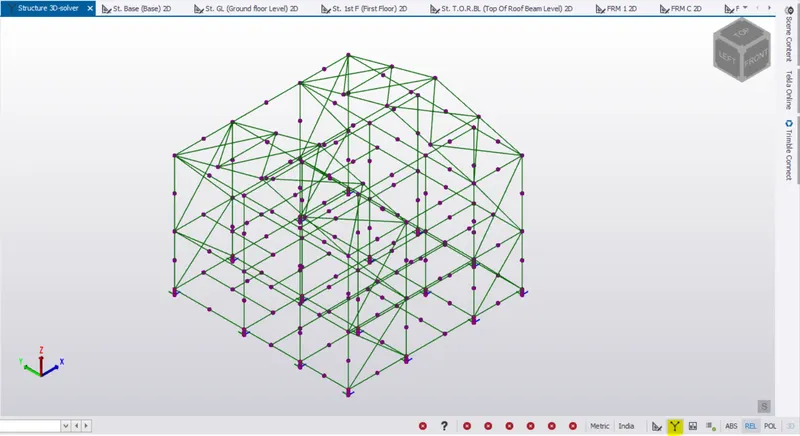
- Solver view:
- Click solver icon to view the nodes
- Validate:
- Click Model ->Validate to check the model.