To Model a RC residential structure using TSD
QUESTION 1
AIM
To create a new file in TSD and set up a model for RC building design based on the following parameters for cover
|
MEMBERS |
IN CONTACT WITH GROUND |
ABOVE GROUND |
|
Column |
50mm |
40mm |
|
Beam |
30mm |
25mm |
|
Slab |
30mm |
25mm |
|
Pile cap |
75mm |
|
|
Foundation |
50mm |
INTRODUCTION
Tekla has the option of redefining the material properties, its specification, and geometry same as ETabs, but with more options
PROCEDURE
- Click on new for creating a new file
- From the home toolbar,>click on the material
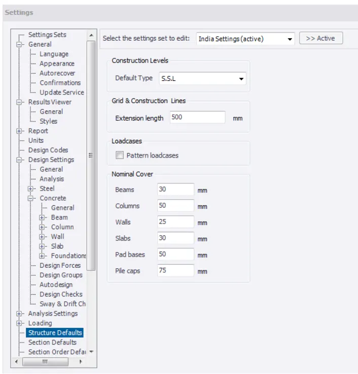
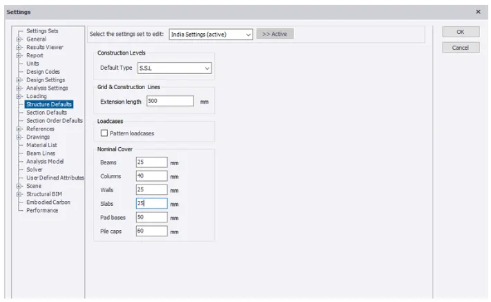
- To change the cover thickness, go to settings>loading>structure defaults
- Select SSL type for in contact with the ground and enter the values
- Similarly, select TOF for above ground and enter the value
RESULT
The new file of TSD is created and the cover is changed as given above
QUESTION 2
AIM
To model grid lines as per Attachment 2, 2.1,2.2
INTRODUCTION
Gridlines indicate where a building element is placed based on a reference point on the plan. Dimensions and gridlines on plans aid in the construction of structural elements. The centerlines of these elements are indicated best to accurately position them on site.
PROCEDURE
- Open a new project and go to the model toolbar
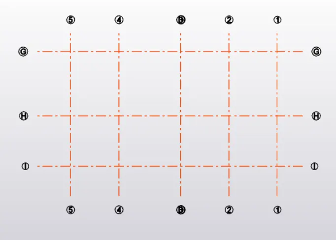
- Select the gridline option and draw a starting grid 1
- Next, select a parallel line and draw grids 2, 3, 4 and 5
- Similarly repeat the same for horizontal grids (A, B, and C)
RESULT
The grid lines are modeled as per the attachment files
QUESTION 3
AIM
To study the given RC building plan and summarize understanding of the plan. Based on studies to explain the location of columns and beam along with hand drawing for each plan
INTRODUCTION
- The prior step of any structural planning is to understand the given architectural drawing and check whether the planning satisfies structural features such as geometry, symmetry in mass and stiffness, and redundancy.
- After the analysis, provide the initial column and beam location before the foundation and other components
PROCEDURE
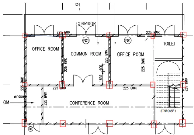
- Given RC office building of size 19.2m * 13.32m
- The column placement should be done in such a way that, it shouldn't interfere with the door, open space ie, between the conference room, etc
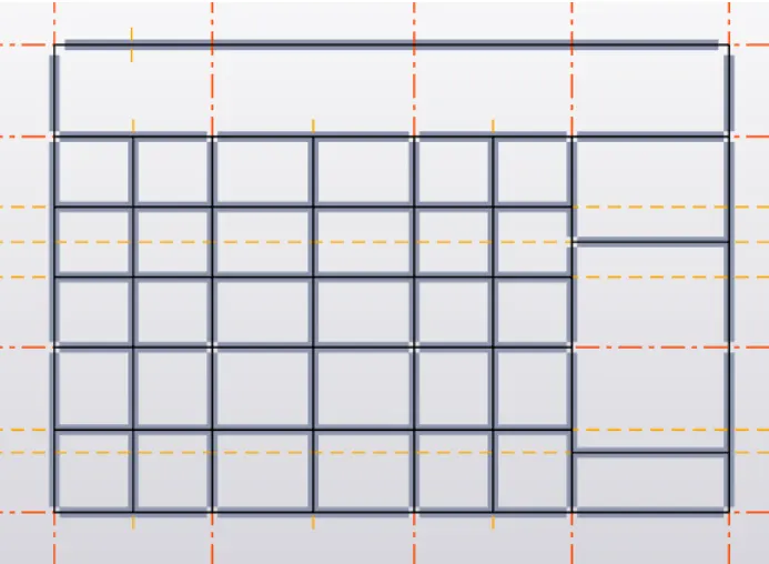
below provide a plan for column and beam, symmetry and uniformity is maintained. Also no clashes with doors.
The column at the periphery of the building can withstand a certain amount of lateral loads
Beam connections along vertical and horizontal ways are provided. Can also provide secondary beam/bracing/pulling etc since the roof is the slope
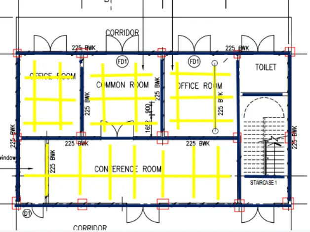
The blue color represent-primary the beam and the yellow color represent a secondary beam
RESULT
The given plan is analyzed and an alternative column and beam design are provided
QUESTION 4
AIM
To define and model concrete columns, beams, and slabs for RC column building from previously defined grids
PROCEDURE
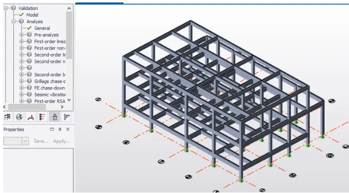
- Define construction levels for G+1 floor RC office building
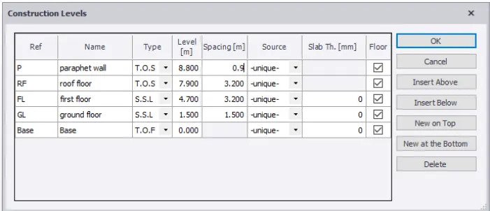
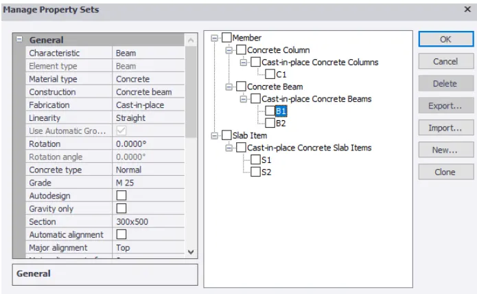
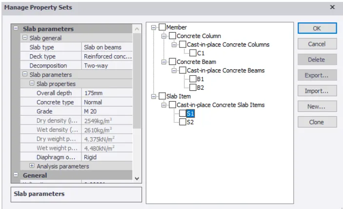
- Go to home toolbar> manage property> define concrete column
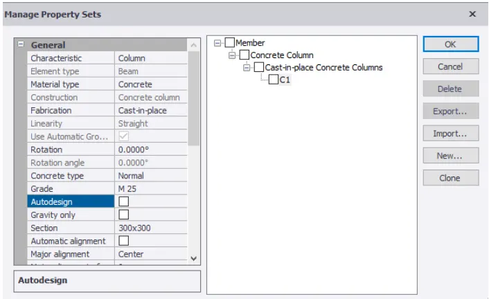
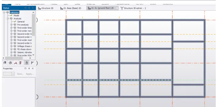
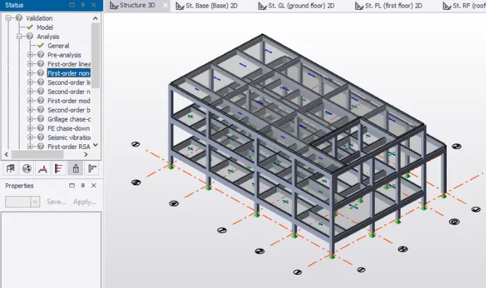
- Model toolbar>concrete column> click on the grid on which column to be placed by setting limits as a base for to roof
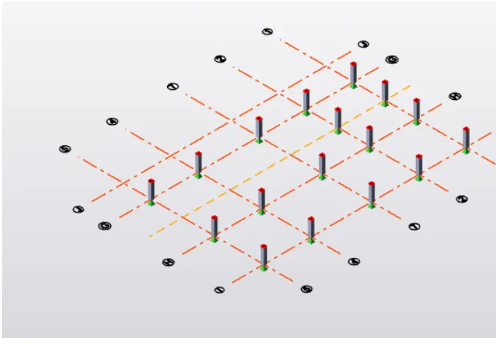
- Define concrete primary and secondary beam in manage property, model them on all floor
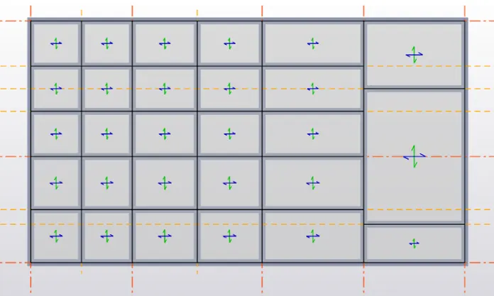
- Similarly, define slabs for one way and two way with differing thicknesses, model them
RESULT
- Construction level is defined
- The concrete column is defined and modeled
- The concrete beam is defined and modeled
- The slab on the beam is defined and modeled