To Model a RC residential structure using TSD
Questions. 1.Setup model for RC building design and based on following parameters for cover
|
MEMBERS |
IN CONTACT WITH GROUND |
ABOVE GROUND |
|
Column |
50mm |
40mm |
|
Beam |
30mm |
25mm |
|
Slab |
30mm |
25mm |
|
Pilecap |
75mm |
|
|
Foundation |
50mm |
|
2. Model grids as per the attachment 2,2.1 and 2.2.
3. Study the layout and write a summary for general arrangement of the structure.
4. Model RC columns, beams and slabs as per your general arrangement.
Solutions:
1.Setup model for RC building design and based on following parameters for cover
|
MEMBERS |
IN CONTACT WITH GROUND |
ABOVE GROUND |
|
Column |
50mm |
40mm |
|
Beam |
30mm |
25mm |
|
Slab |
30mm |
25mm |
|
Pilecap |
75mm |
|
|
Foundation |
50mm |
|
Solution:
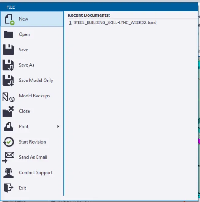
- First thing open the TSD software,and open a new file and in order to open a new file go to the File tab click on that option, then there will be a drop-down list and in that list there will be an option named as the New just click on that option as shown in the below given image:
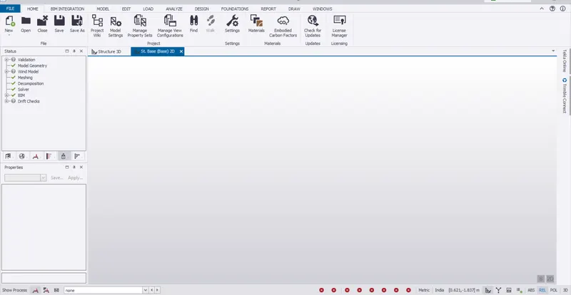
- After that a new file has been created, a new workspace has been created as we can see in the below given image:
- Now in order to setup the model for RC building design first we need to go to the Settings option from the Home tab just click on that option as shown in the below given image:

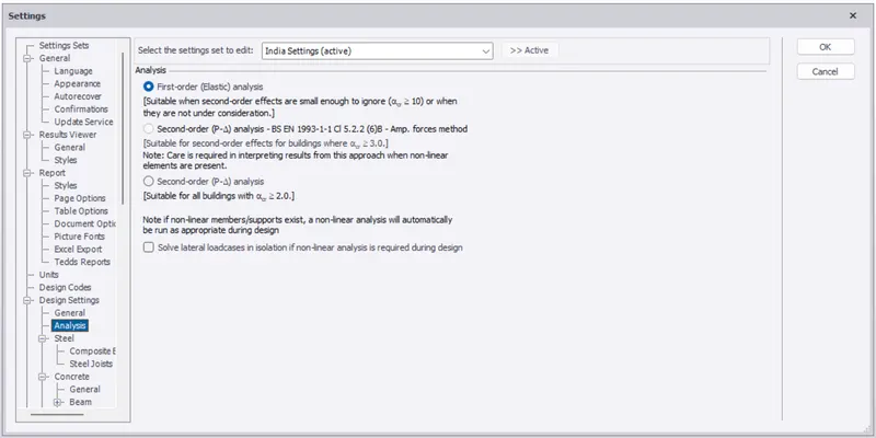
- After clicking on the Settings option there will be a dialouge box named as the Settings as shown in the below given image:
- Now there will be an option in the Settings dialouge box named as the Structure default click on that option just as shown in the below given image:
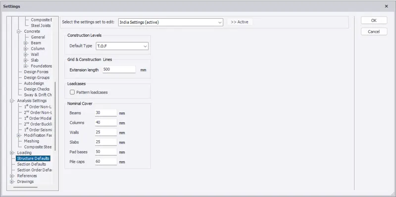
- Fill the necessary details according to the question.
- First we will be adding details for the members which are in contact with the grounds as shown in the below given image:
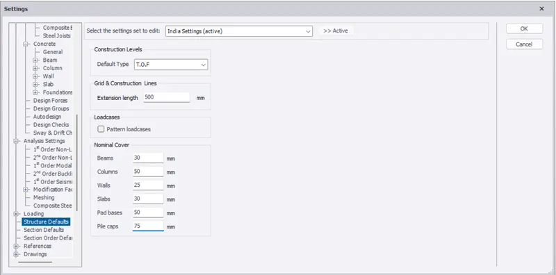
- Next is the members that are above the ground just as shown in the below given image:
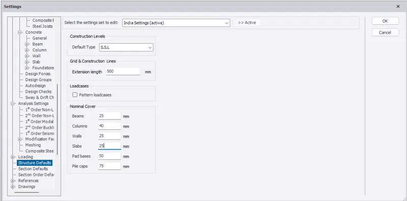
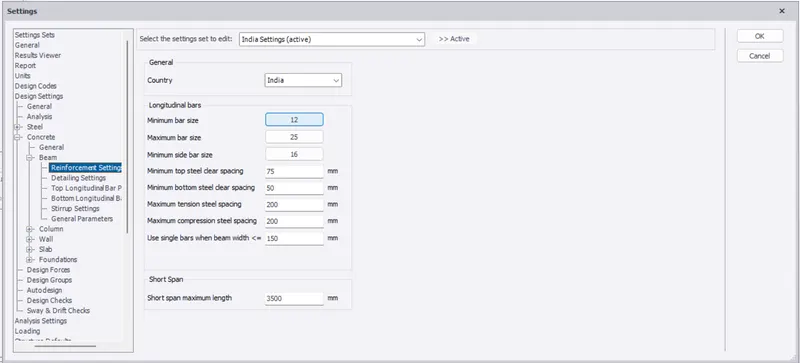
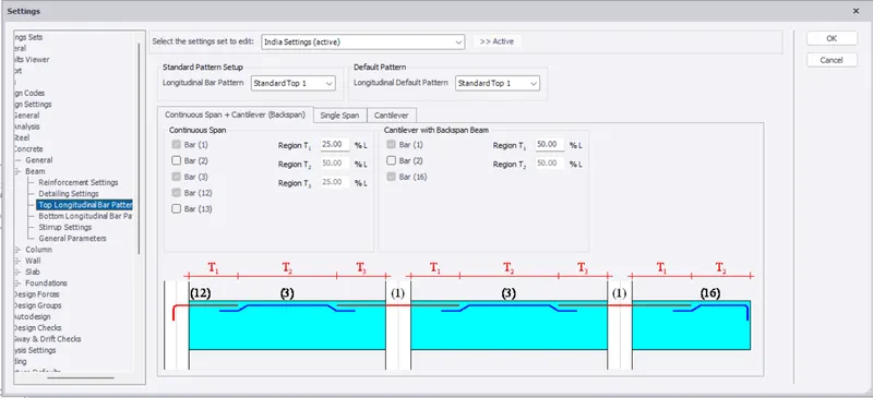
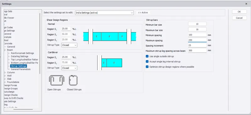
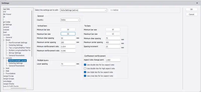
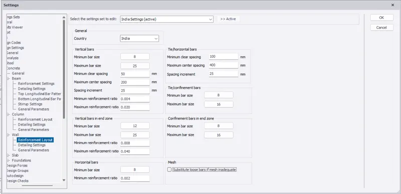
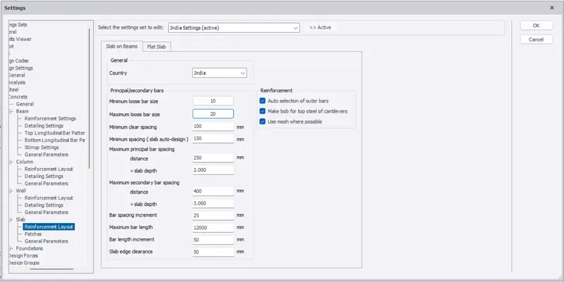
- Now check the other properties also which will be necessary for modelling the RC structure such as the some design settings as we can see in the below given image:
Beam Settings:
Column Settings:
Wall Settings:
Slab Settings:
- Now with all these above steps our model have been setup in the TSD software.
2. Model grids as per the attachment 2,2.1 and 2.2.
Solution:
AIM: To model the grids as per the attachment 2,2.1 and 2.2.
Attachment 2:
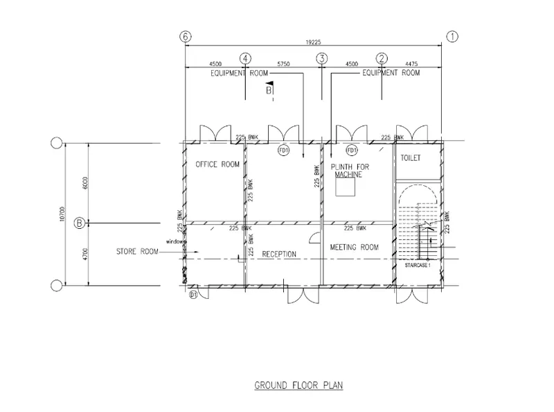
Attachment 2.1:
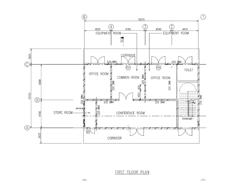
Attachment 2.2:
PROCEDURE:
Construction Levels:
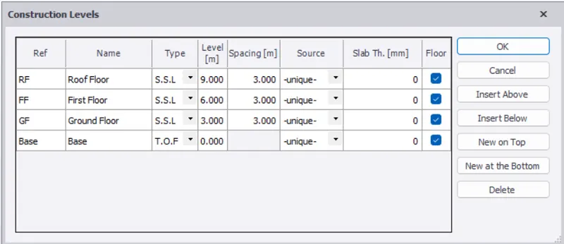
- First we will be creating the construction levels.
- So in order to create the construction level we will be going to the Model toolbar and in that toolbar there will be an icon named as the Construction level,click on that option just as shown in the below given image:
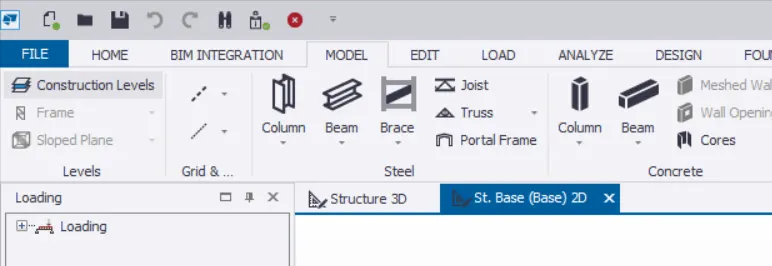
- After that there will be another dialouge box named as the Construction Levels just as shown in the below given image:
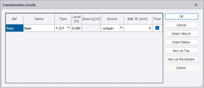
- And now after this name each levels accordingly like base,ground floor,first floor and roof according to thier respective heights which can be assigned to each level just as shown in the below given image:
Grid Lines:
- Now the next step is to model the grid lines.
- And in order to model the grid lines,there will be an option called grid lines,go to the Model ribbon and in that ribbon box there will be an option called Model just click on that option click on that just as shown in the below given image:

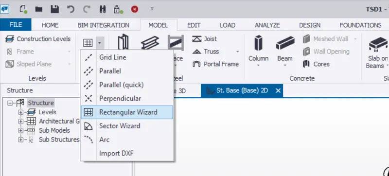
- After that there will be another option called Grids click on that option after clicking on that option there will be a drop-down list and in that list there will be multiple options to create grids.
- So we will be using the option Rectangular Wizard just click on that option after just as shown in the below given image:
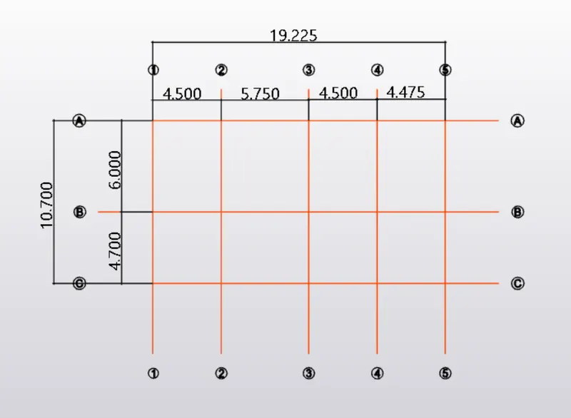
- Below is the image of the grids, below yellow line determines the grid lines for the Ground floor:
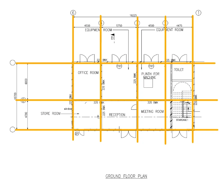
- Make the construction grids as the solid lines so that it will be easier for us to copy the plan in to the other floors also just as we can see in the below given image:
3. Study the layout and write a summary for general arrangement of the structure.
Solution:
Ground Floor Level:
- The Ground Floor is at 2m height from the base.
- The plot size of the plan is of size 19.225*10.7m.
- The Ground Floor consists of Reception, Meeting room, Office room, Toilet, Equipment room and a staircase that leads to the first floor.
- The columns are modelled at the intersection of the grids.
- The brickwall thickness is mentioned as 225mm thck.
First Floor Level:
- The height of the First Floor from the Ground Floor is assumed as 3.5m.
- The First Floor consists of two corridors size of 2.62m X 19.225m.
- The First Floor is of same size as that of ground floor except for the corridor on the either side.
- The First Floor plan consists of Office rooms, Common room, Conference room, Store room and Toilet and Staircase leads to the Roof.
Roof Level:
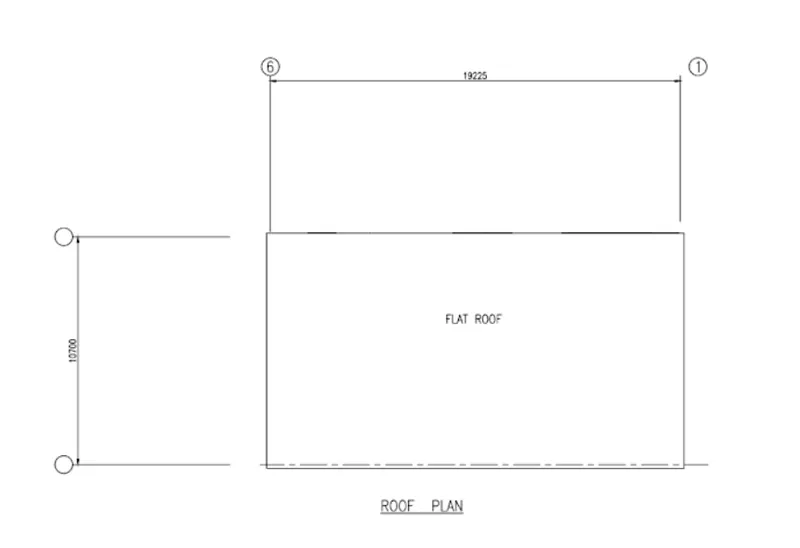
- As we can see above, the roof is a Flat Roof.
4. Model RC columns, beams and slabs as per your general arrangement
Solution:
AIM: To model the RC columns, beams and slabs in the TSD software.
PROCEDURE:
- COLUMNS:
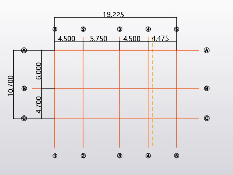
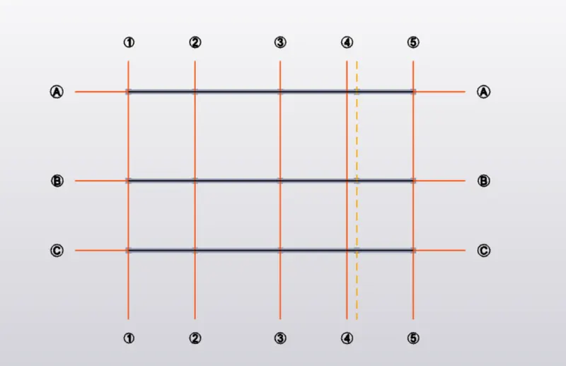
- As we can see in the given plan the column between grid line 4 and 5 is somewhere between 4 & 5 gird line they are not exactly on the 4 & 5 grid lines.
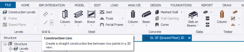
- So in order to create the grid line in between these two grids, just go to the Model tab click on that option then there will be an option named as the Construction line just click on that option just as shown in the below given image:
- Below is the given image after creating the construction line just as shown in the below given image:
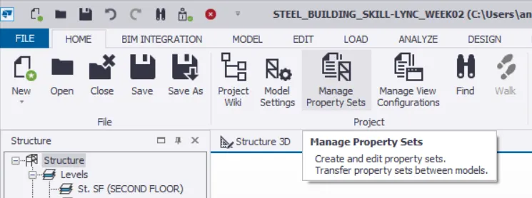
- Next,go to the Home menu and in that ribbon there will be an option called Manage Property Sets just click on that option just as shown in the below given image:
- After this there will be a dialouge box named as the Manage Propert Sets.
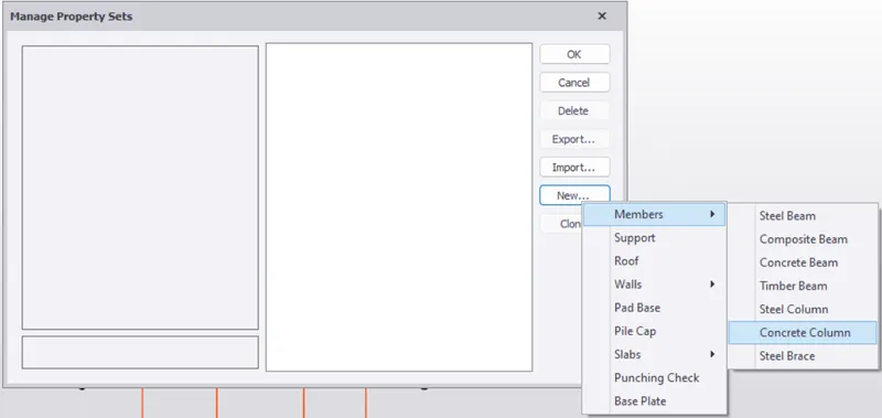
- And in that dialouge box on the right hand side there will be an option called New just click on that option after that there will be another drop-down list and in that list there will be another option called Members just click on that after that there will be another drop-down list and in that list there will be another option called Concrete Column just click on that option just as shown in the below given image:
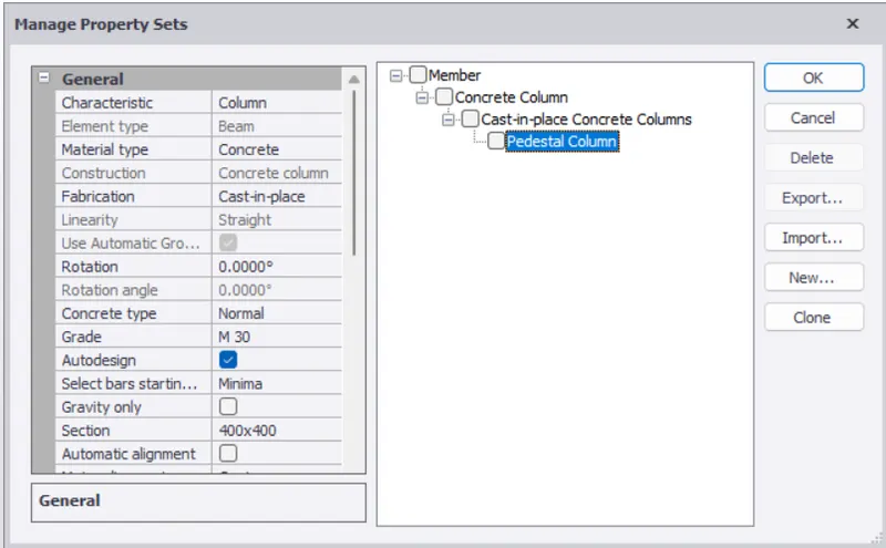
- After this the properties for the Concrete column has been created just as shown in the below given image:
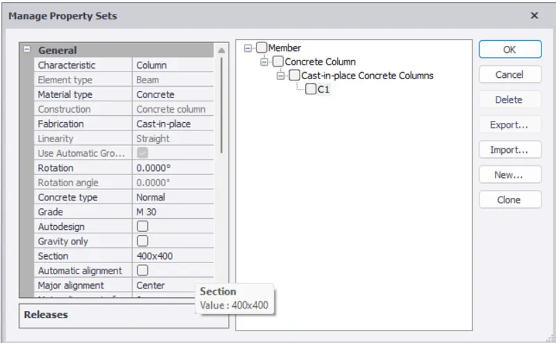
- And now there will be options on the left-hand side,just fill the information just as shown in the below given image:
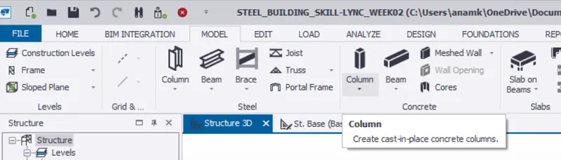
- Now after that go to the Model option and in that option there will be an option named as the Column just click on that option just as shown in the below given image:
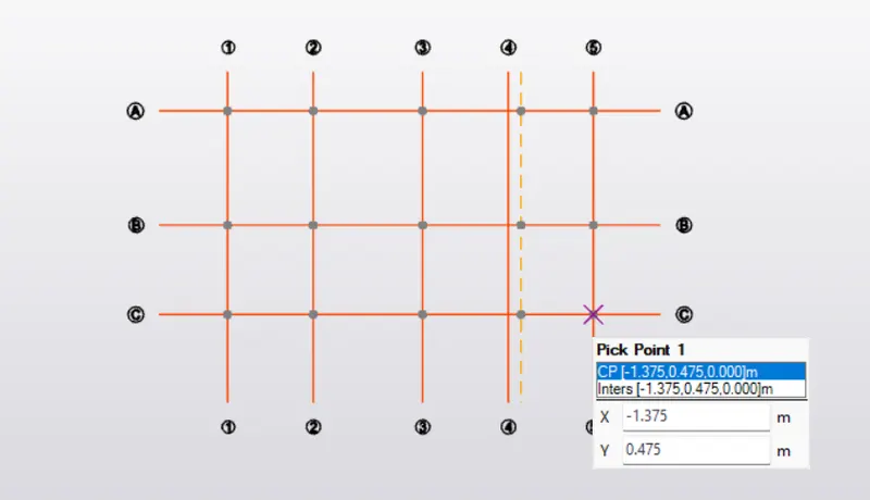
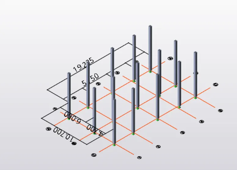
- And after draw the column according to the plan just as the shown in the below given image:
COLUMN IN TSD SOFTWARE(2D-VIEW):
3D-VIEW:
- BEAMS:
- Now we will be creating the beam properties first,and in order to do that first go to the Home tab click on that then there will be another option called Manage Property Sets just click on that option just as shown in the below given image:
- And after that there will be another dialouge box named as the Manage Property Sets and in that dialouge box at the right hand side of that box there is an option called New just click on that option after that there will be another drop-down list and in that list there will be an option Members just click on that option after that there will be another drop-down list and in that list there will be another option called Composite Beams just click on that option just as shown in the below given image:
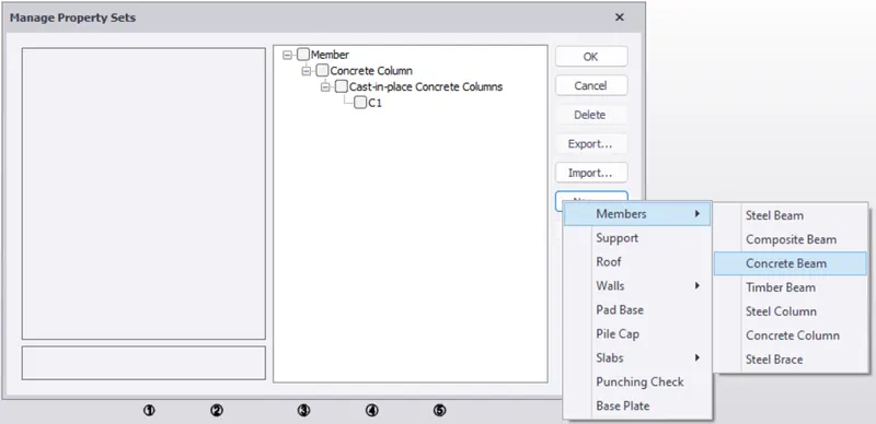
- And now at the left-side of the dialouge box there is an option called Section just click on that option.
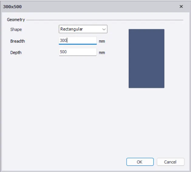
- After that select the section as 300x500 just as shown in the below given image:
- Now go to the Model tab just click on that option and in that tab there will be an option named as the Beam click on that option just as shown in the below given image:

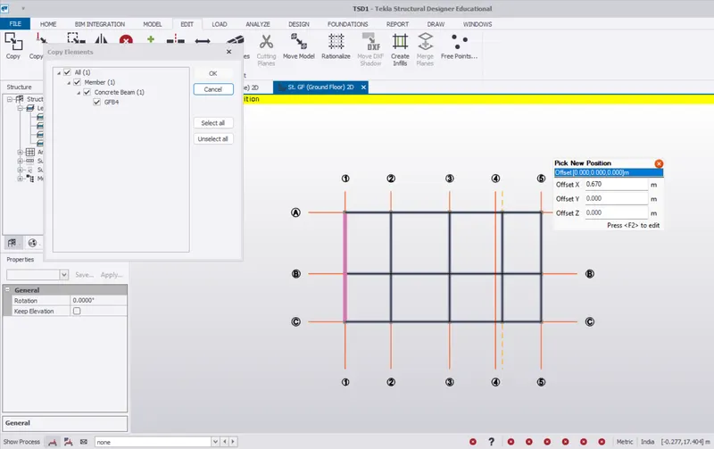
- Now we will be assigning the beams which connects the columns just as shown in the below given image:
GROUND FLOOR BEAMS IN 2D-VIEW:
- Now draw the Vertical beams and after modelling the beam
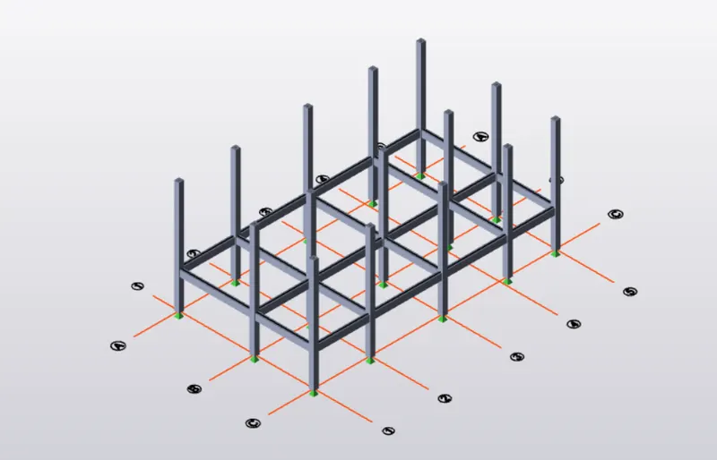
GROUND FLOOR BEAMS IN 3D-VIEW:
FIRST FLOOR BEAMS IN 2D-VIEW:
FIRST FLOOR BEAMS IN 3D-VIEW:
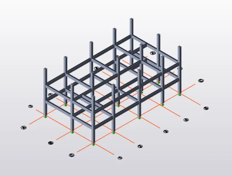
- Now we will be doing the validation/checking the model.
- And in order to validate the model just go to the model tab and there at the right corner there will be an option called Validate just click on that option just as shown in the below given image:

- Validation is done as we can see in the below given image:
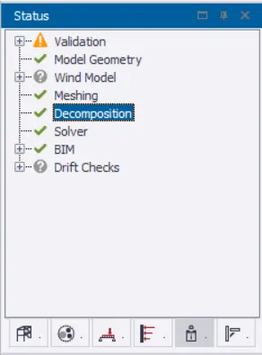
- SLABS:
Slab Properties:
- Now we will be assigning the slab properties.
- And in order to assign the slab properties go to the Home tab then there will be an option called Manage Property Sets just click on that option just as shown in the below given image:
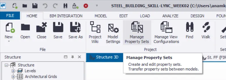
- Now there will be another dialouge box named as the Manage property sets and in that dialouge box on the right hand side of the screen there will be an option called New just click on that option after that there will be a drop-down list and in that list there will be an option Slabs again click on that option then there will be another drop-down list and in that list there will be another option called General Slab Items just click on that option just as shown in the below given image:
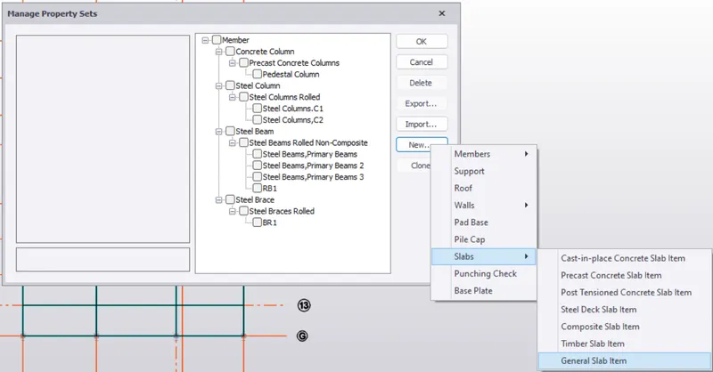
- Now assign the appropriate properties accordingly and rename it as Slab 1 just as shown in the below given image:
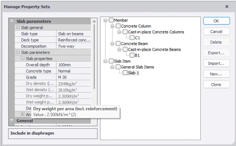
- Now assign the slab properties as shown in the below given image:
Ground Floor Slab:
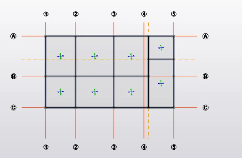
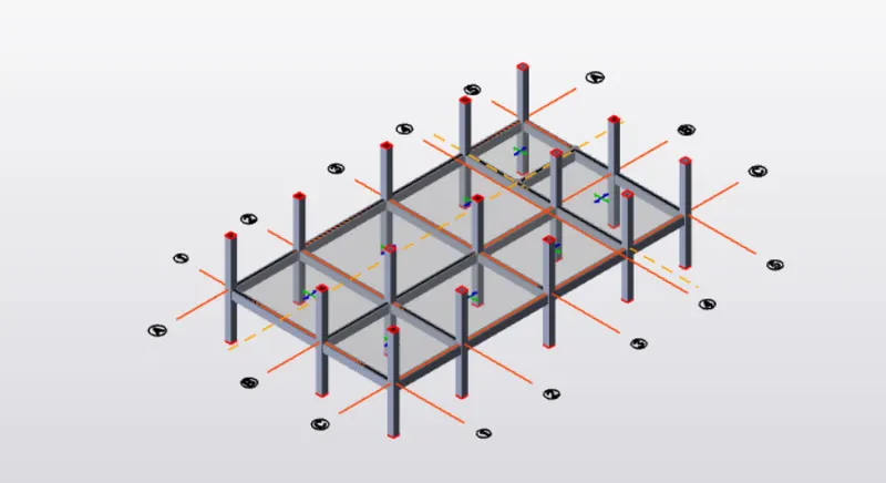
First Floor Slab:
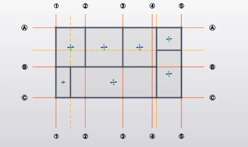
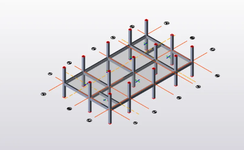
Roof Floor Slab:
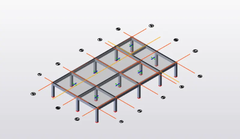
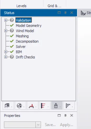
- Now we will be validate the structure.
- After validation there are no errors it means steel structure is good to go upto now as we can see in the below given image:
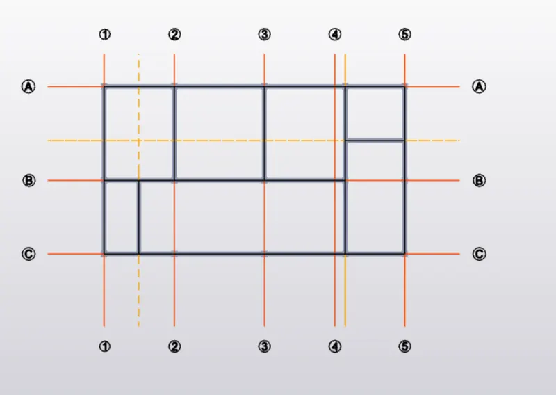
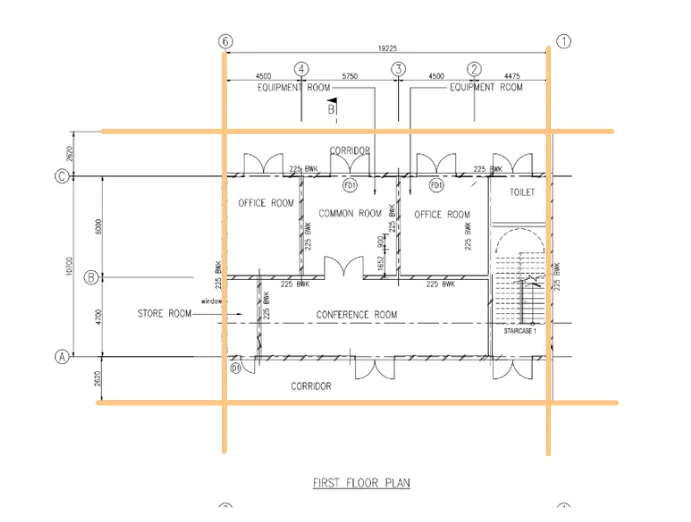
- Now go to the First floor again where we need to model the Corridors.
- So in order to model the corridor,first we need to draw the construction lines where we will be modelling the corridors according to the plan given as we can see in the below given image:
- To draw the construction line, just go to the Model tab click on that option then there will be an option named as the Construction line just click on that option just as shown in the below given image:
- Below is the given image after creating the construction line just as shown in the below given image:
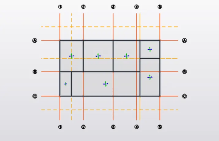
- Now we will be modelling the cantilever beam and in order to model the cantilever beam make the one end as the cantilever end otherwise it can show some errors in the software.
- Now first model the beam as we have already modelled for the previously just as shown in the below given image:
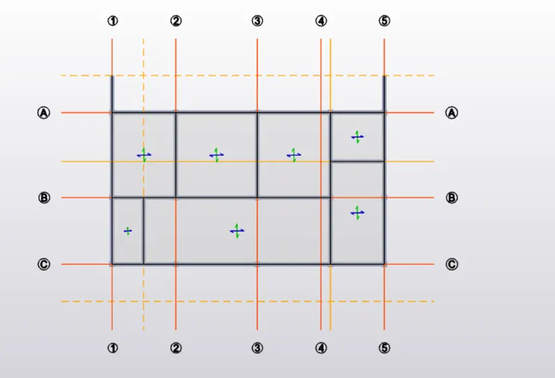
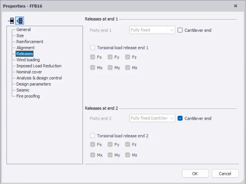
- Repeat the same procedure for the other end also just as we can see in the below given image:
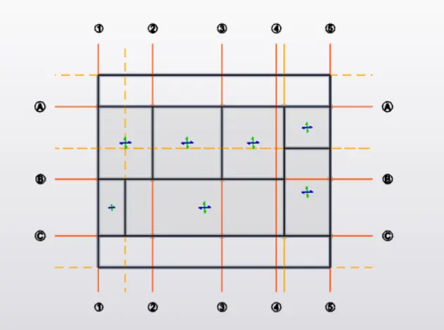
Slab:
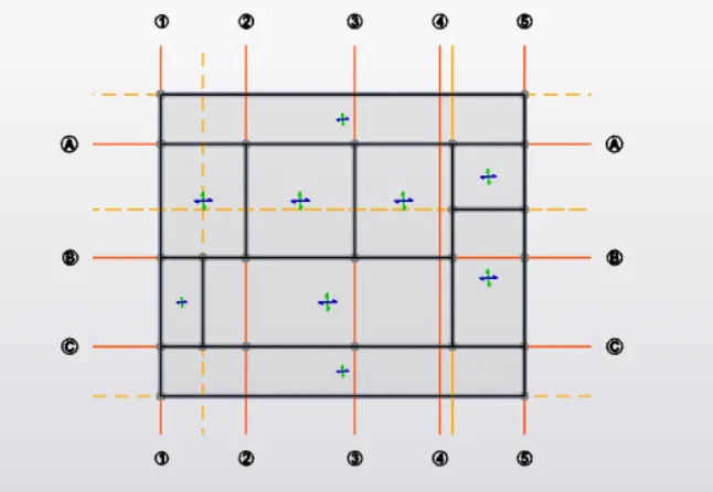
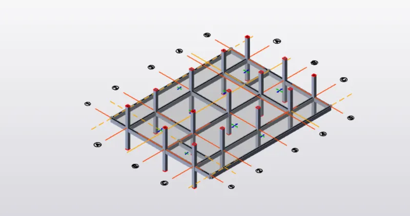
- The beams, columns and the slabs are sucessfully modelled in the TSD software as we can see in the below given image:
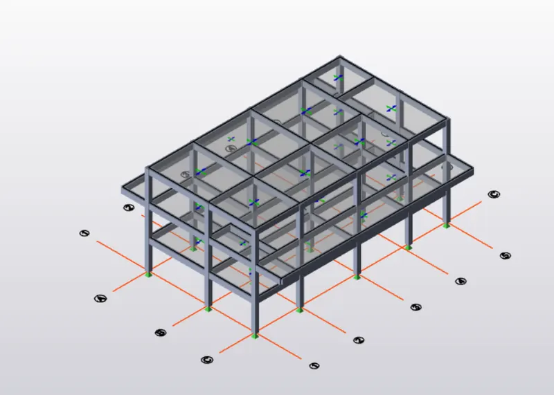
- Now we will be validate the structure.
- After validation there are no errors it means steel structure is good to go upto now as we can see in the below given image: