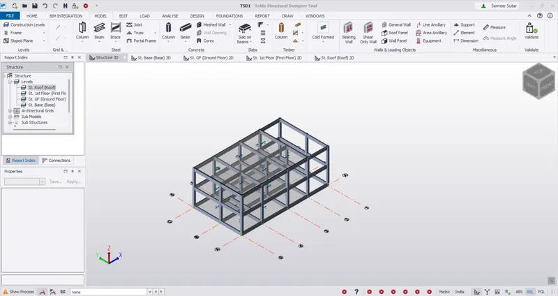
To Model a RC residential structure using TSD
1. Setup model for RC building design and based on following parameters for cover
|
MEMBERS |
IN CONTACT WITH GROUND |
ABOVE GROUND |
|
Column |
50mm |
40mm |
|
Beam |
30mm |
25mm |
|
Slab |
30mm |
25mm |
|
Pilecap |
75mm |
|
|
Foundation |
50mm |
Aim - To setup model for RC building design and based on following parameters for cover.
Tools Used - New, Setting.
Procedure -
Open a new file in TSD by clicking on New in the file tab.
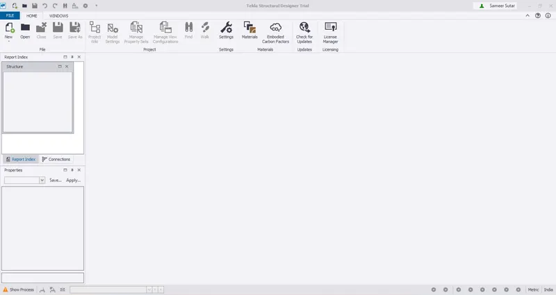
In the new file created, click on setting in the file tab.
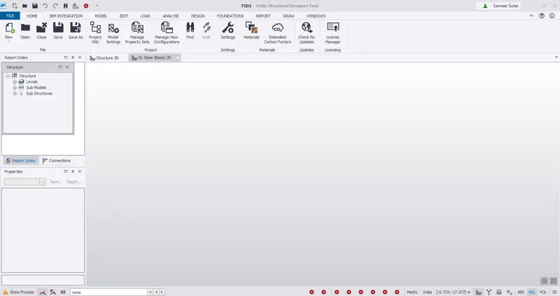
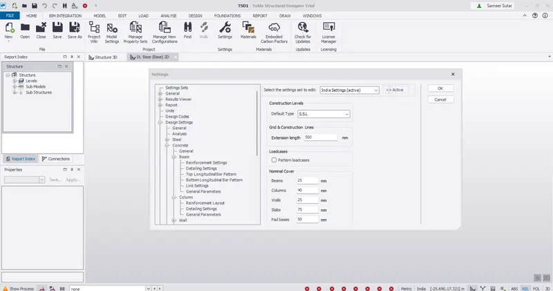
In the setting dialogue box thats opens,click on structure defaults and select TOF Construction levels dropdown and then enter the values of
cover for beams, Columns, slab, pilecap and foundation as 50,30,30,75 and 50 respectively.
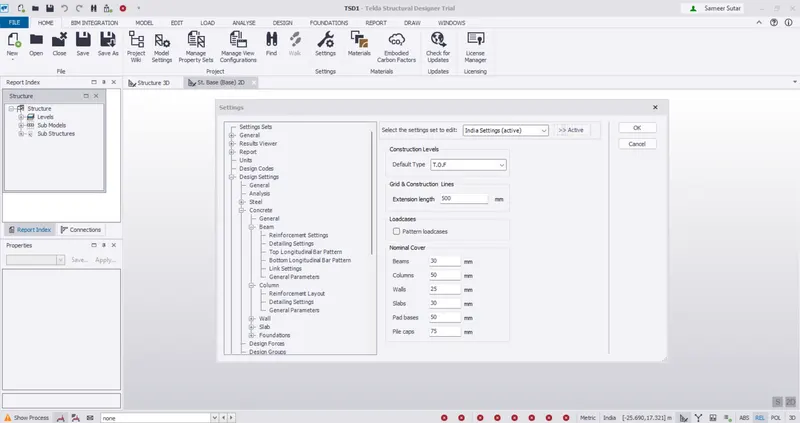
Now, choose SSL in construction levels dropdown and enter the values of cover for beam, column and slab as 40,25 and 25 respectively and
click ok.
Result -
The model is setup with the given cover values for the members.
2. Model grids as per the attachment 2,2.1 and 2.2.
Aim - To model grids as per attachments provided.
Tools Used - Construction Levels, Grids, Parallel.
Procedure -
Click on construction levels in the model tab.
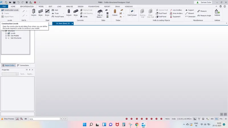
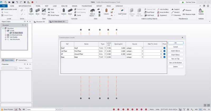
In the dialogue box that opens click on insert above and create levels as ground floor, First Floor and Roof Floor with spacing as
0.5m, 3.6m and 3.6m between the floors ap per attachment. Set the Base as TOF and GF,FF as SSL and RF as TOS and click Ok.
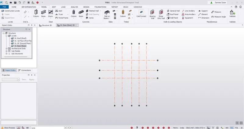
Now in the model tab, click on grid and draw grids with the help of parallel quick and offset as per attachement.

Result -
The Grids are created as attachment.
3. Study the layout and write a summary for general arrangement of the structure.
Aim - To study the layout and write a summary for general arrangement of the structure.
Toos Used - Attachements, Pain Tools.
Study and Summary.
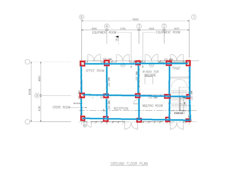
Ground Floor Plan.
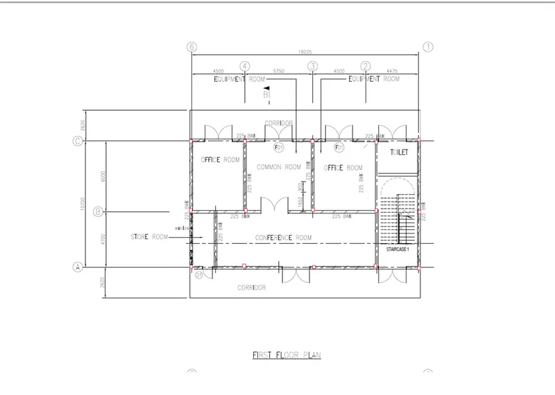
As we can see that there are beams between all the columns that is connecting all the grid intersections, the arrangement of beams and columns
are shown in diagram.
Red box represents columns and Blue lines represent Beams.
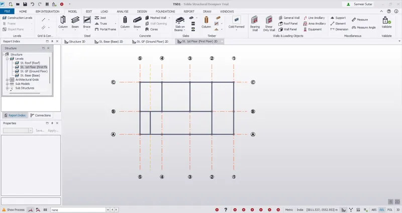
First Floor Plan.
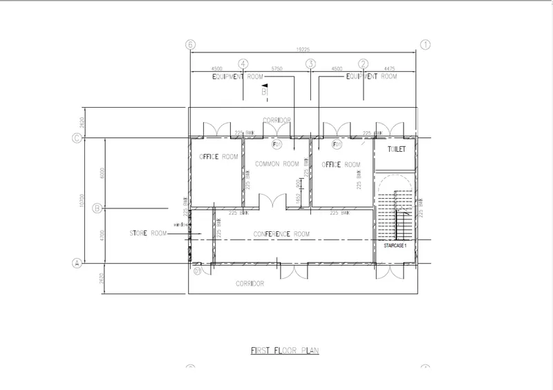
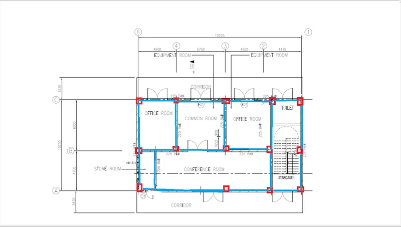
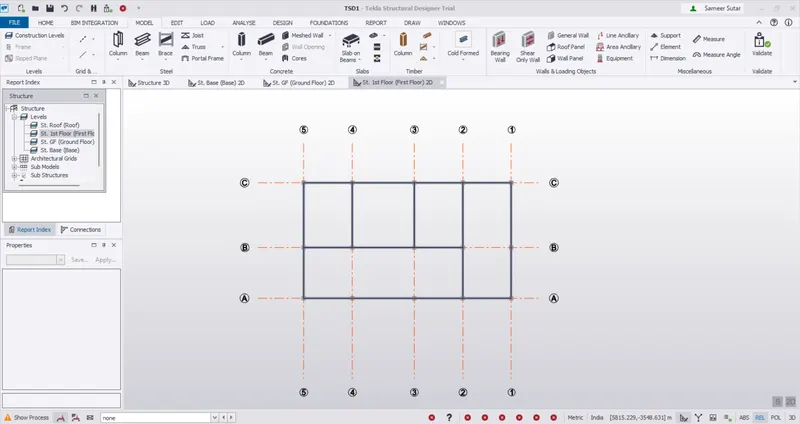
The columns are drawn as per the placement given in attachment and then the beams are placed connecting all the columns excepting the
beam between conference room as per the plan.
Red Box represents columns and blue lines represent Beams.
Result -
The study is done and the placements of the members are done in paint.
4. Model RC columns, beams and slabs as per your general arrangement.
Aim - To model RC columns, Beams and slab as per general arrangement.
Tools Used - Manage Property Sets, Column, Beams, slab on Beams, Property Window, Validate.
Procedure -
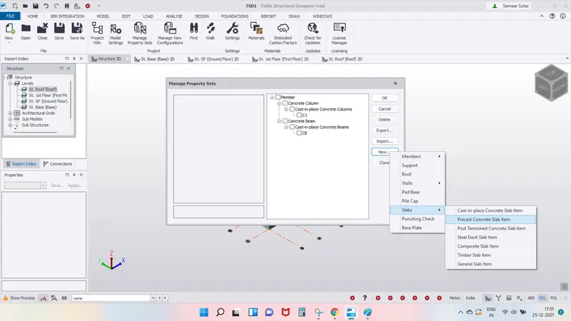
Click on manage property sets in Home tab and create a new concrete column and column beam with appropriate grade, section etc.
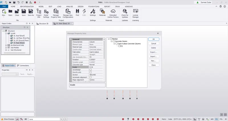
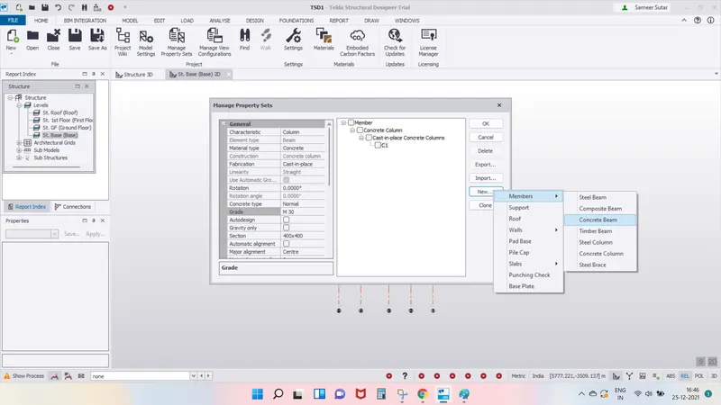
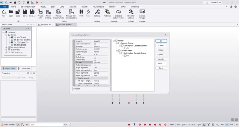
Now open base level and click on column in Model tab and pick points whereever the columns are required.
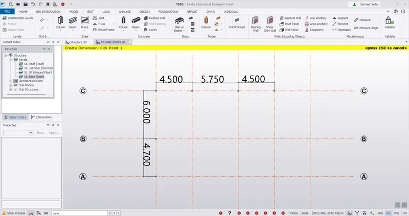
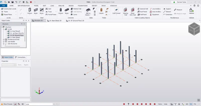
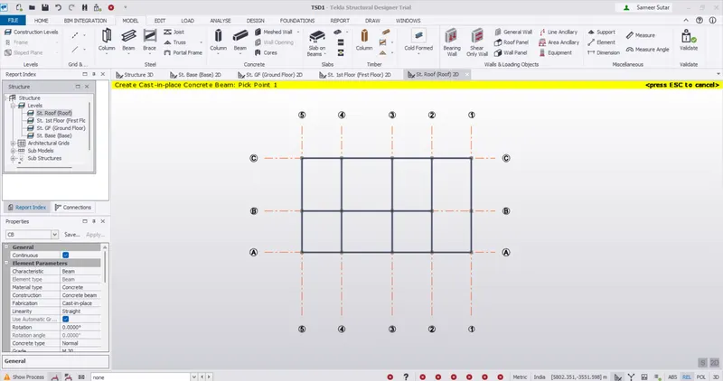
Click on beams in model tab in concrete division and in the ground floor level, draw the beams as per the arrangment layout created
previously.
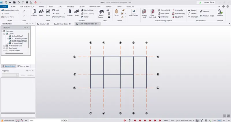
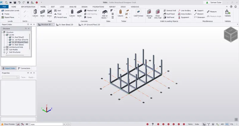
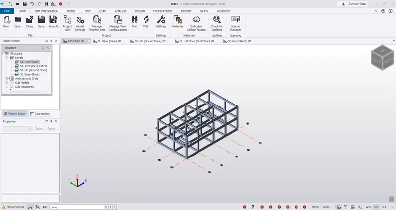
Similarly, create concrete beams for all floors.
Click on manage property sets in Home tab and create slab items.
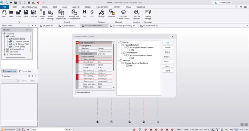
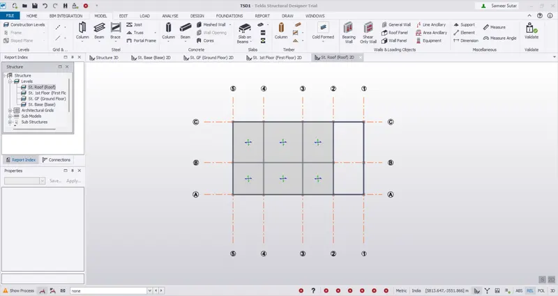
Click on slab on beams and select the two or one way as required and select the bay to create slabs on all floors.
Result -
The required members are created and structure is validated to be error free.