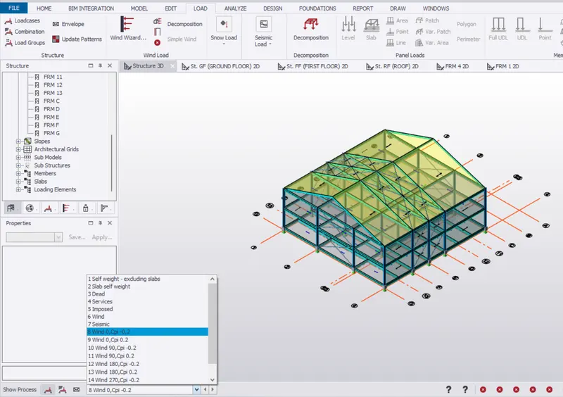
To calculate wind load for industrial steel structures and to apply it by using TSD
Questions:
- Generate manual wind loading in the design report based IS code as per the following input
- Basic wind speed = 39m/s.
- Terrain category 2.
- Based on the above calculation apply the loadings on the model.
- On a separate model generate wind loading using wind wizard.
Solutions:
- Generate manual wind loading in the design report based IS code as per the following input
- Basic wind speed = 39m/s.
- Terrain category 2.
Solution:
AIM: To generate the manual wind loading in the design report based IS code according to the given input.
- Basic Wind Speed = 39 m/s.
- Terrain Category = 2.
Manual Calculations:
Given Data:
Basic wind speed = 39 m/s.
Terrain Category = 2.
Greater horizontal dimensions of structure, l = 18m.
Shorter side dimension, w = 18m.
Eaves level height of the structure, h = 14m.
Width of frame-1 between A and B = 7.2m.
According to the IS 875 Part-lll Clause 6.3.1:
Vb = Basic wind speed = 39 m/s. (According to the IS code 875 Part:2 Appendix:A).
Design Wind Speed, Vz = Vb*k1*k2*k3*k4.
Where,
k1 = Probability Factor.
k2 = Terrain height, structure factor.
k3 = Topography Factor.
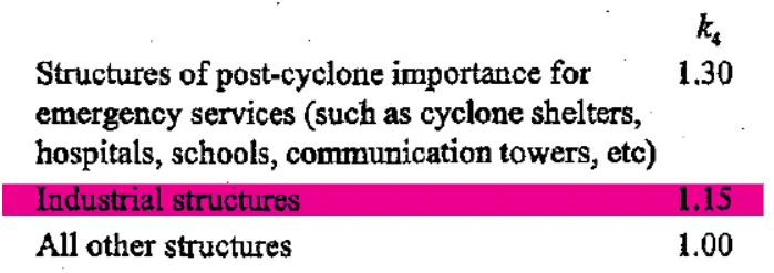
k4 = Importance Factor for the cyclonic region.
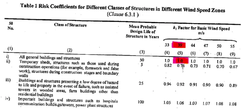
- According to IS 875 Part-lll: Table:1 the value of k1 = 1.0.
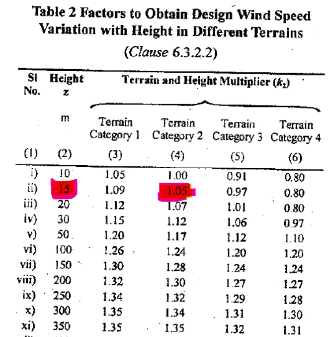
- According to IS 875 Part-lll, Table:2, the value of k2 = 1.05.
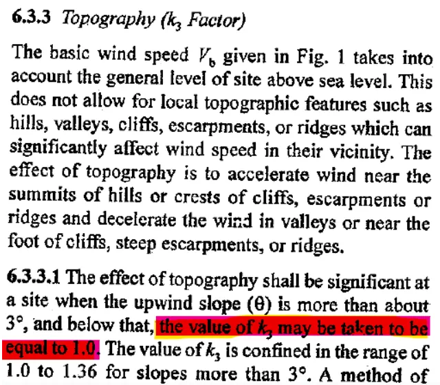
- According to IS 875 Part-lll, the value of k3 = 1.
- According to IS Part-lll, the value of k4 = 1.15.
Calculations:
Wind Speed = 39 m/s.
Life Period of the structure = 50 years.
Terrain Category = 2.
Class Structure = A.
Step 1: Design Wind Speed and Design Wind Pressure:
- Design Wind Speed:
Design Wind Speed, Vz = Vb*k1*k2*k3*k4.
Design Wind Speed, Vz = 39*1.0*1.05*1*1.15.
Design Wind Speed, Vz = 47.09 m/s.
Design Wind Pressure, Pz = 0.6*`Vz^2`
Pz = 0.6*`(47.09)^2`
Design Wind Pressure, Pz = 1330 N/sq.m.
Design Wind Pressure, Pz = 1.3 kN/sq.m.
Roof angle = 25 degree.
Internal pressure co-efficient = 0.50 (Upto 20% opening).
Internal pressure co-efficient = +0.50 (Upto 20% opening).
Step 2 : Ratio of wall and roof co-efficient:
Wall:
l/w = 1.00.
h/w = 0.67.
Roof:
h/w = 0.67.
Wind directions +Y,-Y,+X,-X:
| Wind Load along +Y-direction (Face A): | ||
| Cpi + | Cpi - | |
| l/w =1 | l/w = 1 | |
| External Pressure Co-efficient,Cpe | 0.7 | 0.7 |
| Internal Pressure Co-efficient,Cpi | 0.5 | -0.5 |
| Net-Pressure,Cp = Cpe-Cpi | 0.2 | 1.2 |
| Design wind pressure on the wall,Pz (kN/sq.m) | 1.33 | 1.33 |
| Loading to be applied on the wall, Cp x Pz | 1.463 | 1.596 |
| K2 factor from table 2:1.05 | 1.536 | 1.675 |
| Wind Load along +Y-direction (Face B): | ||
| Cpi + | Cpe - | |
| l/w = 1 | l/w = 1 | |
| External Pressure Co-efficient,Cpe | -0.25 | -0.25 |
| Internal Pressure Co-efficient,Cpi | 0.5 | -0.5 |
| Net-Pressure,Cp = Cpe-Cpi | -0.75 | 0.25 |
| Design wind pressure on the wall,Pz (kN/sq.m) | 1.33 | 1.33 |
| Loading to be applied on the wall, Cp x Pz | -0.99 | 0.33 |
| K2 factor from table 2:1.05 | -1.03 | 0.34 |
| Wind Load along +Y-direction ( Face C and D): | ||
| Cpi + | Cpi - | |
| h/w = 0.67 | h/w = 0.67 | |
| External Pressure Co-efficient,Cpe | -0.6 | -0.6 |
| Internal Pressure Co-efficient,Cpi | 0.5 | -0.5 |
| Net-Pressure,Cp = Cpe-Cpi | -1.1 | -0.1 |
| Design wind pressure on the wall,Pz (kN/sq.m) | 1.33 | 1.33 |
| Loading to be applied on the wall, Cp x Pz | -1.463 | -0.133 |
| K2 factor from table 2:1.05 | -1.53 | -0.14 |
| Wind Load along -Y-direction (Face A): | ||
| Cpi + | Cpi - | |
| l/w = 1 | l/w = 1 | |
| External Pressure Co-efficient,Cpe | -0.3 | -0.3 |
| Internal Pressure Co-efficient,Cpi | 0.5 | -0.5 |
| Net-Pressure,Cp = Cpe-Cpi | -0.7 | 0.2 |
| Design wind pressure on the wall,Pz (kN/sq.m) | 1.33 | 1.33 |
| Loading to be applied on the wall, Cp x Pz | -0.931 | 0.266 |
| K2 factor from table 2:1.05 | -0.977 | 0.279 |
| Wind Load along -Y-direction (Face B): | ||
| Cpi + | Cpi - | |
| l/w =1 | l/w = 1 | |
| External Pressure Co-efficient,Cpe | 0.7 | 0.7 |
| Internal Pressure Co-efficient,Cpi | 0.5 | -0.5 |
| Net-Pressure,Cp = Cpe-Cpi | 0.2 | 1.2 |
| Design wind pressure on the wall,Pz (kN/sq.m) | 1.33 | 1.33 |
| Loading to be applied on the wall, Cp x Pz | 0.266 | 1.596 |
| K2 factor from table 2:1.05 | 0.28 | 1.67 |
| Wind Load along -Y-direction (Face C and D): | ||
| Cpi+ | Cpi- | |
| h/w = 0.67 | h/w = 0.67 | |
| External Pressure Co-efficient,Cpe | -0.7 | -0.7 |
| Internal Pressure Co-efficient,Cpi | 0.5 | -0.5 |
| Net-Pressure,Cp = Cpe-Cpi | -1.2 | -0.2 |
| Design wind pressure on the wall,Pz (kN/sq.m) | 1.33 | 1.33 |
| Loading to be applied on the wall, Cp x Pz | -1.6 | -0.266 |
| K2 factor from table 2:1.05 | -1.68 | -0.28 |
| Wind Load along +Y-direction (Face E and F :0 degree): | ||
| Cpi+ | Cpi- | |
| h/w = 0.67 | h/w = 0.67 | |
| External Pressure Co-efficient,Cpe | -1.03 | -1.03 |
| Internal Pressure Co-efficient,Cpi | 0.5 | -0.5 |
| Net-Pressure,Cp = Cpe-Cpi | -1.53 | -0.53 |
| Design wind pressure on the wall,Pz (kN/sq.m) | 1.33 | 1.33 |
| Loading to be applied on the wall, Cp x Pz | -2.034 | -0.704 |
| K2 factor from table 2:1.05 | -2.13 | -0.74 |
| Wind Load along +Y-direction (Face G and H :0 degree): | ||
| Cpi+ | Cpi- | |
| h/w = 0.67 | h/w = 0.67 | |
| External Pressure Co-efficient,Cpe | 0.5 | -0.5 |
| Internal Pressure Co-efficient,Cpi | 0.5 | -0.5 |
| Net-Pressure,Cp = Cpe-Cpi | -1 | 0 |
| Design wind pressure on the wall,Pz (kN/sq.m) | 1.33 | 1.33 |
| Loading to be applied on the wall, Cp x Pz | -1.33 | 0 |
| K2 factor from table 2:1.05 | -1.4 | 0 |
| Wind Load along +X-direction (Face E and F :90 degree): | ||
| Cpi + | Cpi- | |
| h/w = 0.67 | h/w = 0.67 | |
| External Pressure Co-efficient,Cpe | -0.8 | -0.8 |
| Internal Pressure Co-efficient,Cpi | 0.5 | -0.5 |
| Net-Pressure,Cp = Cpe-Cpi | -0.13 | -0.3 |
| Design wind pressure on the wall,Pz (kN/sq.m) | 1.33 | 1.33 |
| Loading to be applied on the wall, Cp x Pz | -0.173 | -0.4 |
| K2 factor from table 2:1.05 | -0.23 | -0.532 |
| Wind Load along +X-direction (Face G and H :90 degree): | ||
| Cpi + | Cpi - | |
| h/w = 0.67 | h/w = 0.67 | |
| External Pressure Co-efficient,Cpe | -0.612 | -0.612 |
| Internal Pressure Co-efficient,Cpi | 0.5 | -0.5 |
| Net-Pressure,Cp = Cpe-Cpi | -1.112 | -0.112 |
| Design wind pressure on the wall,Pz (kN/sq.m) | 1.33 | 1.33 |
| Loading to be applied on the wall, Cp x Pz | -1.48 | -0.148 |
| K2 factor from table 2:1.05 | -1.554 | 0.1554 |
| Wind Load along -Y-direction (Face G and H :0 degree): | ||
| Cpi+ | Cpi- | |
| h/w = 0.67 | h/w = 0.67 | |
| External Pressure Co-efficient,Cpe | -1.03 | -1.03 |
| Internal Pressure Co-efficient,Cpi | 0.5 | -0.5 |
| Net-Pressure,Cp = Cpe-Cpi | -1.53 | -0.53 |
| Design wind pressure on the wall,Pz (kN/sq.m) | 1.33 | 1.33 |
| Loading to be applied on the wall, Cp x Pz | -2.034 | -0.704 |
| K2 factor from table 2:1.05 | -2.13 | -0.74 |
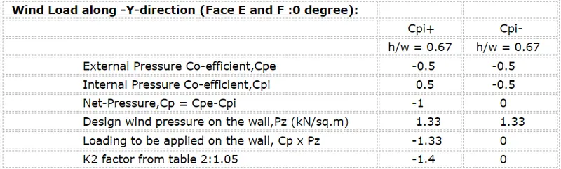
| Wind Load along -Y-direction (Face E and F :0 degree): | ||
| Cpi+ | Cpi- | |
| h/w = 0.67 | h/w = 0.67 | |
| External Pressure Co-efficient,Cpe | -0.5 | -0.5 |
| Internal Pressure Co-efficient,Cpi | 0.5 | -0.5 |
| Net-Pressure,Cp = Cpe-Cpi | -1 | 0 |
| Design wind pressure on the wall,Pz (kN/sq.m) | 1.33 | 1.33 |
| Loading to be applied on the wall, Cp x Pz | -1.33 | 0 |
| K2 factor from table 2:1.05 | -1.4 | 0 |
| Wind Load along -X-direction (Face G andH :90 degree): | ||
| Cpi+ | Cpi- | |
| h/w = 0.67 | h/w = 0.67 | |
| External Pressure Co-efficient,Cpe | -0.8 | -0.8 |
| Internal Pressure Co-efficient,Cpi | 0.5 | -0.5 |
| Net-Pressure,Cp = Cpe-Cpi | -0.13 | -0.3 |
| Design wind pressure on the wall,Pz (kN/sq.m) | 1.33 | 1.33 |
| Loading to be applied on the wall, Cp x Pz | -0.173 | -0.4 |
| K2 factor from table 2:1.05 | -0.23 | -0.532 |
| Wind Load along -X-direction (Face E and F :90 degree): | ||
| Cpi+ | Cpi- | |
| h/w = 0.67 | h/w = 0.67 | |
| External Pressure Co-efficient,Cpe | -0.612 | -0.612 |
| Internal Pressure Co-efficient,Cpi | 0.5 | -0.5 |
| Net-Pressure,Cp = Cpe-Cpi | -1.112 | -0.112 |
| Design wind pressure on the wall,Pz (kN/sq.m) | 1.33 | 1.33 |
| Loading to be applied on the wall, Cp x Pz | -1.48 | -0.148 |
| K2 factor from table 2:1.05 | -1.554 | 0.155 |
2.Based on the above calculation apply the loadings on the model.
Solution:
AIM: To apply the calculated wind loads manually calculated loads on the model in the TSD software.
PROCEDURE:
Step_01:
- Below are the combinations for the wind loads that we are going to apply on the model.
Wall Loadings (Face A, B, C and D):
- Y +Cpi.
- Y -Cpi.
- -Y +Cpi.
- -Y -Cpi.
Wall Loadings (Face EF and GH):
- Y +Cpi.
- Y -Cpi.
- -Y +Cpi.
- -Y -Cpi.
- X +Cpi.
- X -Cpi.
- -X +Cpi.
- -X -Cpi.
- Now open the Tekla Model our previous assignment in the software.
- Now go to the Load option just click on that just as shown in the below given image:

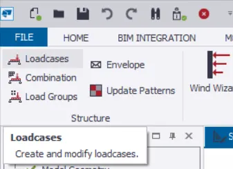
- Now there will be an option in the Load ribbon at the left side of the screen as Load combinations just click on that option just as shown in the below given image:
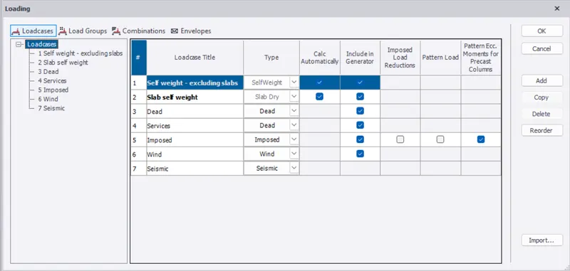
- After that there will be another dialouge box named as the Loadings opens as shown in the below given image:
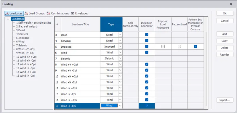
- Now in the above dialouge box add the wind load combinations just as shown in the below given image:
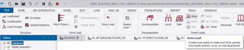
- Now we will be applying the wind load cases and to apply the wind loads in the model go to the load ribbons and then in that ribbon there will be an option in the Panel Loads there will be an option called Area just click on that option just as shown in the below given image:
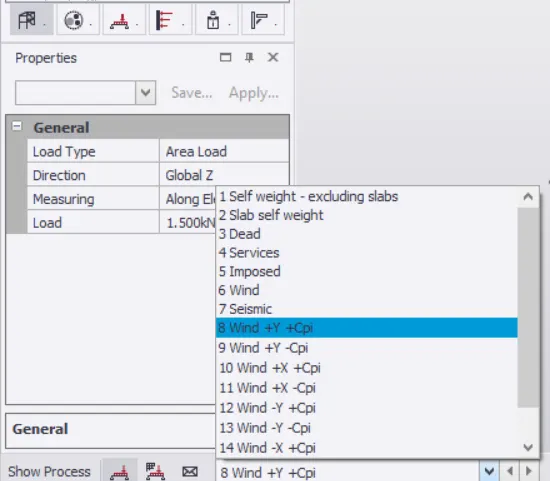
- Now select the frame and select the combination which is present at the bottom of the workspace just as shown in the below given image:
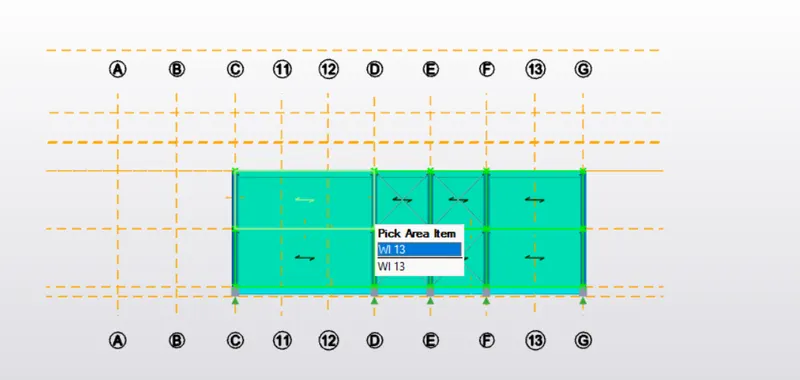
- Wind Load +Y +Cpi (Face A):
- Wind Load +Y-Cpi (Face A):
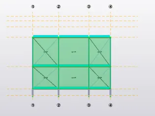
- Wind Load +Y+Cpi (Face B):
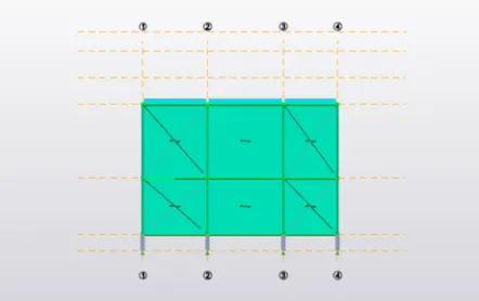
- Wind Load +Y-Cpi (Face B):
- Wind Load +Y+Cpi (Face C):
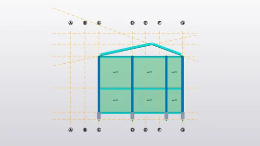
- Wind Load +Y-Cpi (Face C):
- Wind Load +Y+Cpi (Face D):
- Wind Load +Y-Cpi (Face D):
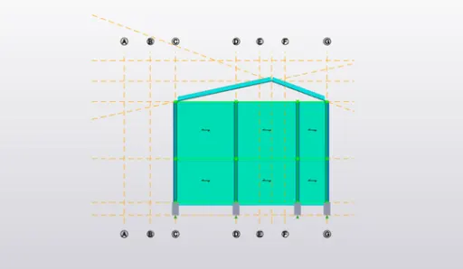
- Wind Load -Y+Cpi (Face A):
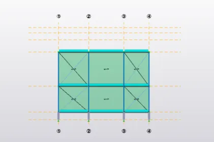
Wind Load -Y-Cpi (Face A):
- Wind Load -Y+Cpi (Face B):
- Wind Load -Y-Cpi (Face B):
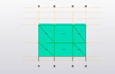
- Wind Load -Y+Cpi (Face C):
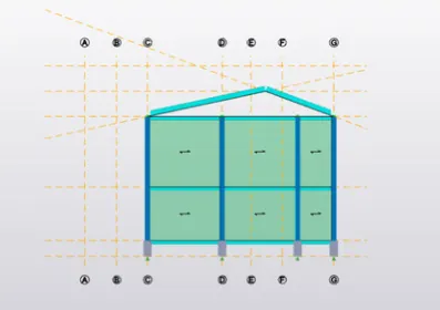
- Wind Load -Y-Cpi (Face C):
- Wind Load -Y+Cpi (Face D):
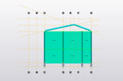
- Wind Load -Y-Cpi (Face D):
ROOF LOADS:
- Wind Load +Y+Cpi (Face EF):
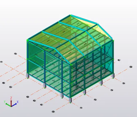
- Wind Load +Y-Cpi (Face EF):
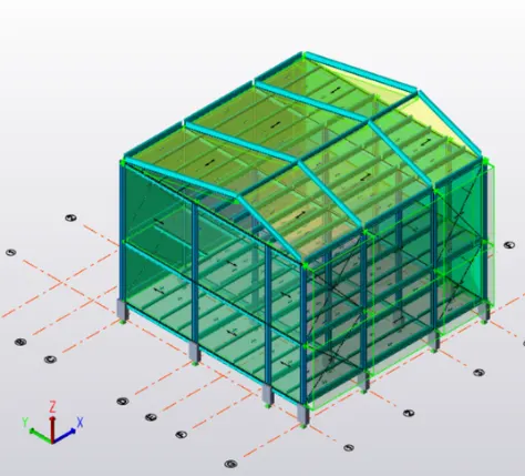
- Wind Load +Y+Cpi (Face GH):
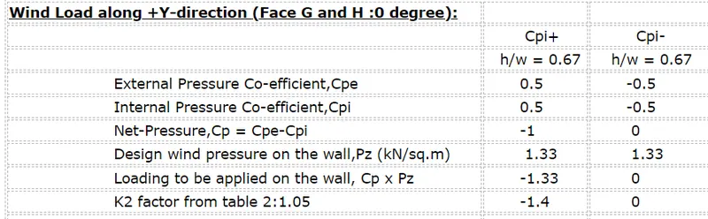
- Wind Load +Y-Cpi (Face GH) has Zero value:
- Wind Load +X+Cpi (Face EF):
- Wind Load +X-Cpi (Face EF):
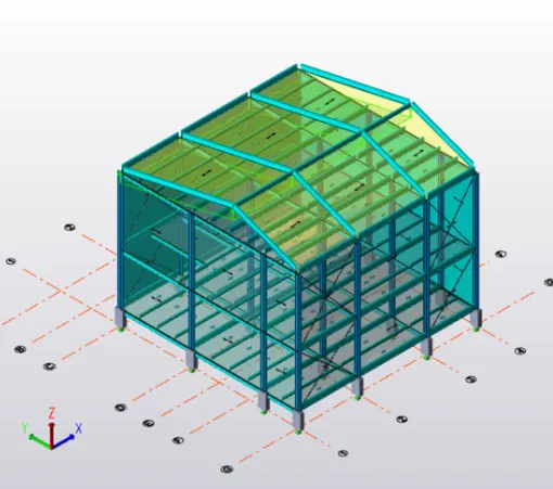
- Wind Load +X+Cpi (Face GH):
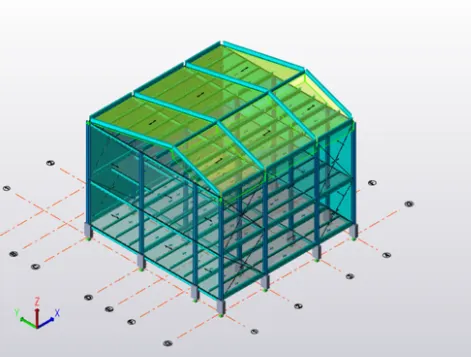
- Wind Load +X-Cpi (Face GH):
- Wind Load -Y+Cpi (Face GH):
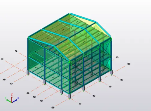
- Wind Load -Y-Cpi (Face GH):
- Wind Load -Y+Cpi (Face EF):
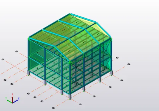
- Wind Load -Y-Cpi (Face EF) has zero value:
- Wind Load -X+Cpi (Face GH):
- Wind Load -X-Cpi (Face GH):
- Wind Load -X+Cpi (Face EF):
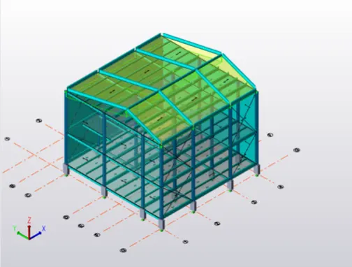
- Wind Load -X-Cpi (Face EF):
3. On a separate model generate wind loading using wind wizard.
Solution:
AIM: To generate the wind loading using the wind wizard in the TSD software.
PROCEDURE:
- Now we will be generating the wind loading in the new model using the wind wizard in TSD software.
- So first of all we will be generating the new model.
- After generating the new model go to the Load ribbon just as shown in the below given image:
- After that in the Load ribbon there will be an option called Wind Wizard just click on that option just as shown in the below given image:
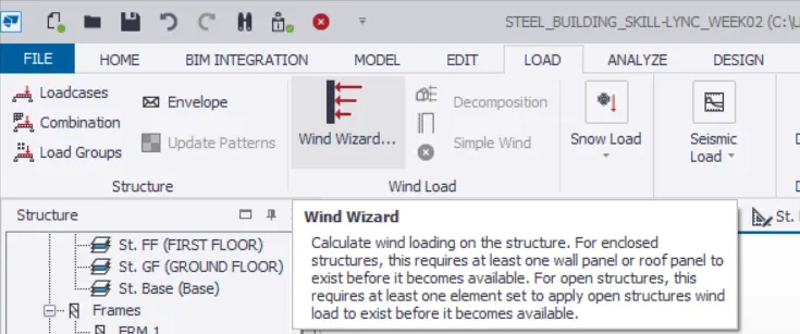
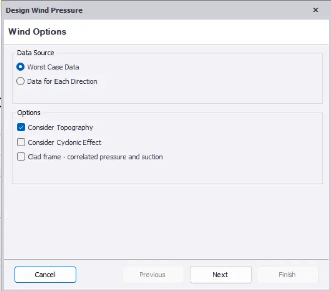
- After clicking the option wind wizard, then there will be a dialouge box named as the Design Wind Pressure.
- And in that dialouge box click on the Worst Case Data and Consider Topography and then click on the option Next just as shown in the below given image:
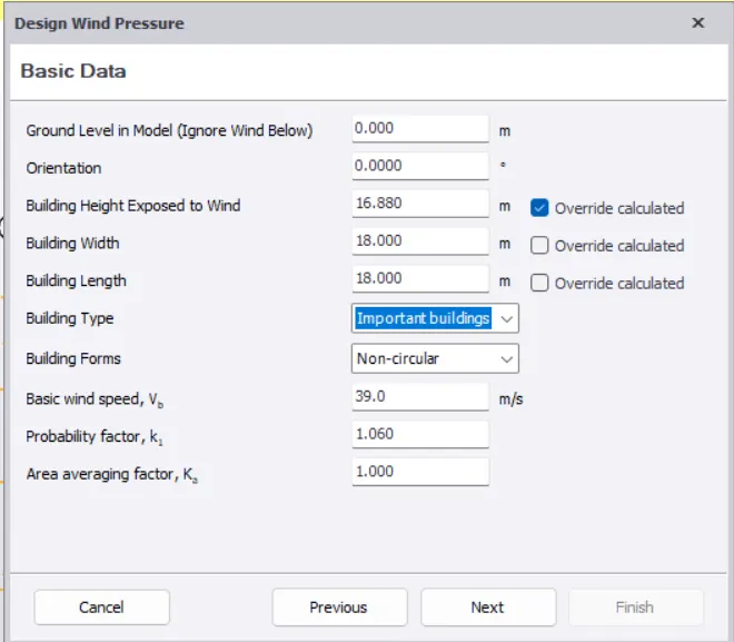
- After that there will be another dialouge box named as the Design Wind Pressure and fill the necessary data and the click on the option Next just as shown in the below given image:
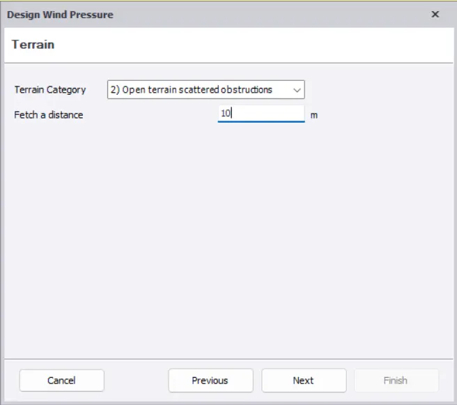
- After that there will be another dialouge box named as the Design Wind Pressure fill out the necessary data just as shown in the below given image:
- After that there will be another dialouge box named as the Design Wind Pressure and check for the results and then click on the Next option just as shown in the below given image:
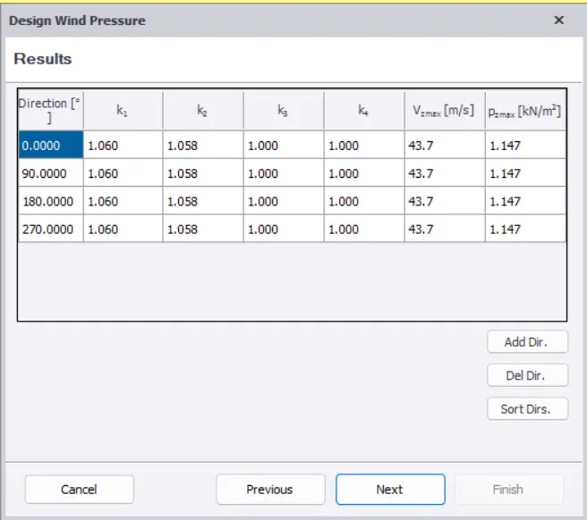
- After that there will be another dialouge box named as the Design Wind Pressure and the next result page appears and then click on the option Finish just as shown in the below given image:
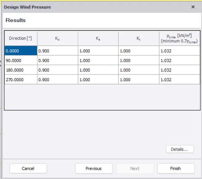
- After that go to the Load ribbon and in that menu bar there will be an option called Wind Loadcases just click on that option just as shown in the below given image:
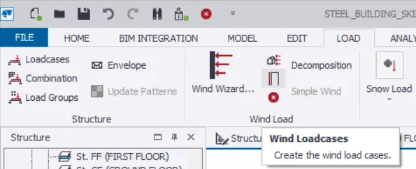
- After that there will be another dialouge box named as the Wind Loadcases and generate the load cases just as shown in the below given image:
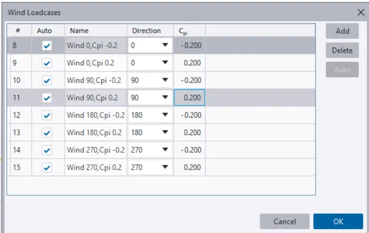
- Now the wind loads is generated using the Wind Wizard option: