To calculate wind load for industrial steel structures and to apply it by using TSD
1 AIM:
To generate manual wind loading in the design report based IS code as per the following input
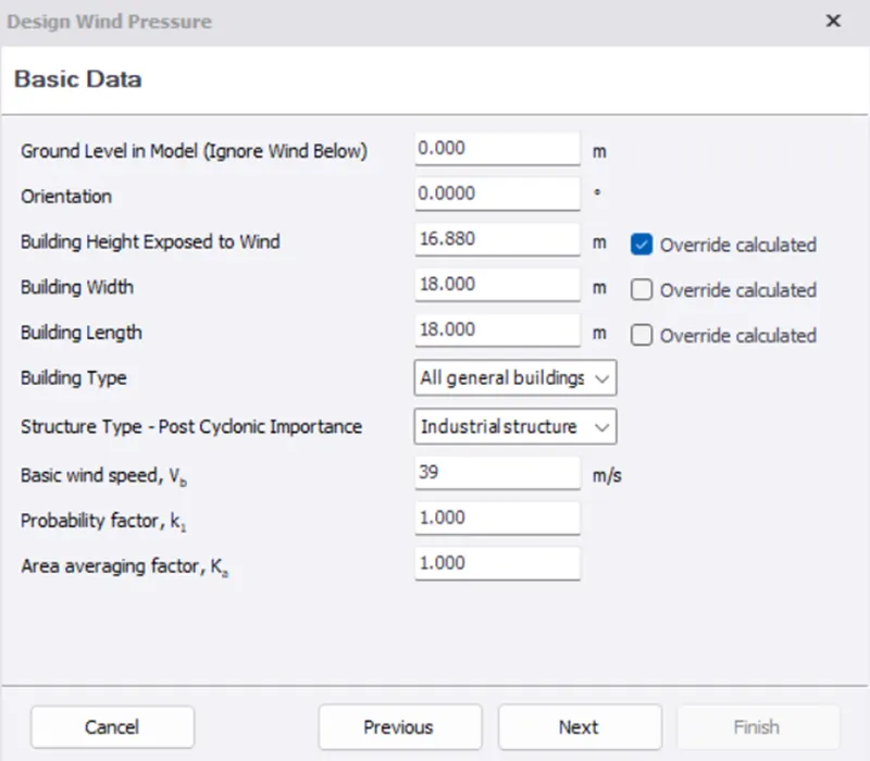
- Basic wind speed = 39m/s
- Terrain category 2
Procedure:
- Given, basic wind speed , Vb = 39 m/s ; Terrain Category = 2
- Length of the building, l = 18 m
- Breadth of the building, w = 18 m
- Height of the building, h = 16.88 m
Step 1: Finding Design Wind Speed:
- Referring to IS 875 P3, Vz = Vb k1 k2 k3 k4 according to Cl 6.3
- Where Vz – Design wind speed
- K1 – probability factor
- K2 – terrain roughness and height factor
- K3 – topography factor
- K4 – importance factor for cyclonic region
- From table 1, k1 = 1
- From table 2, for height of the building 16.88 m and terrain category 2 , k2 is obtained by interpolation.
- For 15 m , k2 = 1.05
- For 20 m , k2 = 1.07
- Therefore, for 16.88 m , k2 = 1.057 = 1.06
- From Cl 6.3.3 , k3 = 1 since, theta < 3(flat terrain)
- From Cl 6.3.4, k4 = 1.15 for Industrial structures
- Substituting all the above values, Vz = 39 * 1 * 1.06 * 1 * 1.15 = 47.54 m/s
Step 2: Finding Design Wind Pressure:
- From Cl 7.2, wind pressure, pz = 0.6 Vz^2
- pz = 0.6 * 47.54 ^ 2 = 1356.1 N/m2
- pz = 1.356 kN/m2
Step 3: Design Wind Load:
Wind Load on Wall:
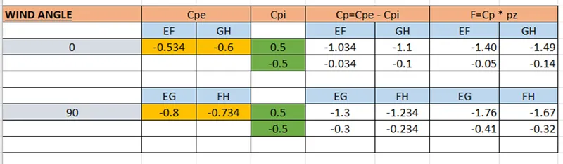
- From Cl 7.3.1, F = (Cpe – Cpi) A pz = Cp * pz
- Cpe is found from Table 5 of IS 875 P3 for h/w and l/w ratios
- h/w = 16.88 / 18 = 0.94
- l/w = 18/18 = 1

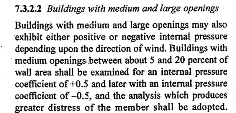
- Lets consider medium openings in which Cpi = + 0.5 / -0.5 according to Cl 7.3.2.2 of IS 875 part 3
Wind angle 0:
A – windward side , B – leeward side
- Lets consider the loading Wind + Y + Cpi , Wind + Y – Cpi and Wind – Y + Cpi , Wind – Y – Cpi for all four sides A, B, C and D
Wind angle 90:
C – windward side , D – leeward side
- Lets consider the loading Wind + X + Cpi , Wind + X – Cpi and Wind – X + Cpi , Wind – X – Cpi for all four sides A, B, C and D

Wind Load on Roof:
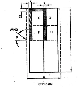
- For calculating wind load, h/w ratio and roof angle is required to find Cpe
- In our case, h/w = 0.94 , roof angle = tan -1 (3.88/9) = 23.32 deg

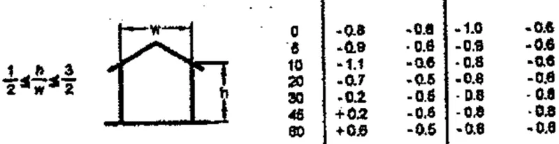
For a roof angle of 23.32 deg, we need to interpolate between 20 and 30
Wind angle 0, EF = -0.534 , GH = -0.6
Wind angle 90, EG = -0.8 , FH = -0.734
Result:
- Design wind speed and pressure are calculated initially
- Then using h/w values and l/w values, the Cpe values are found for wind angles 0 and 90 for all 4 sides
- Cpi values are assumed
- For + Cpi and – Cpi , the various values are worked out and design wind loads are found for walls and roofs
Thus we calculate wind loads on walls and roofs
- Aim:
To apply the loadings on the model based on the above loadings
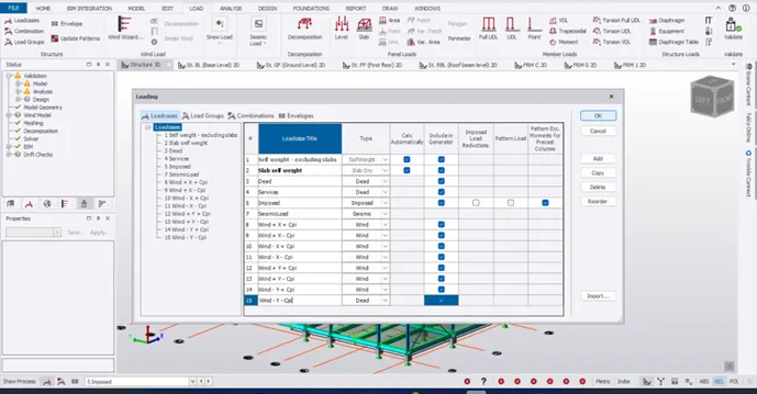
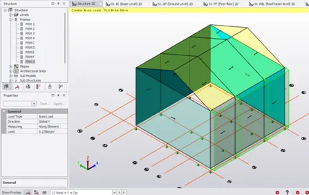
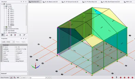
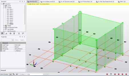
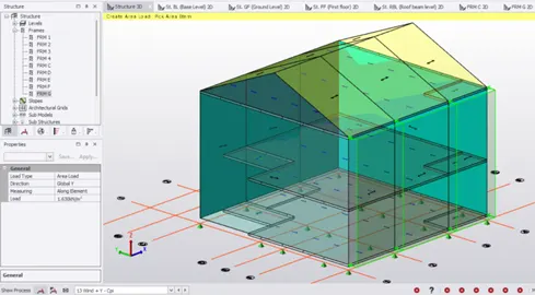
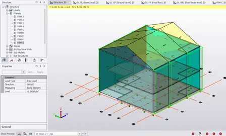
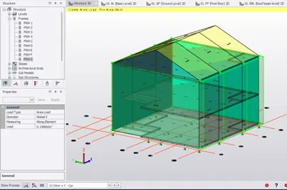
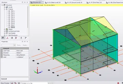
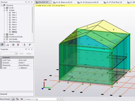
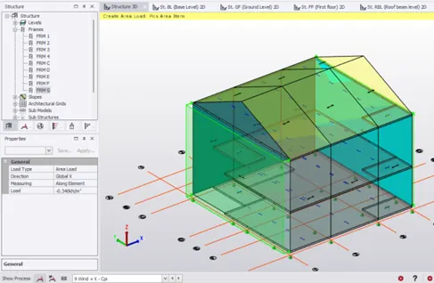
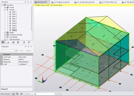
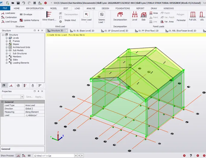
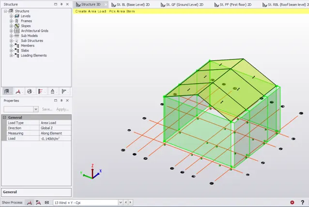
Wind + X + Cpi:
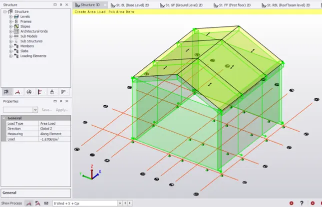
Wind + X – Cpi:
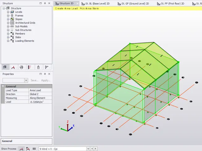
- Repeat the same procedure for -X and – Y directions too
- For -Y direction interchange A and B sides
- For -X direction interchange C and D sides
- Similarly for roofs interchange EF and GH for -Y and EG and FH for – X
Result:
The various load combinations +Y + Cpi, +Y – Cpi , + X +Cpi and +X – Cpi ; -Y + Cpi, -Y – Cpi, -X+Cpi, -X-Cpi are thus generated for walls and roofs
- AIM:
To generate wind loading on a separate model using wind wizard
Procedure:
- Use ‘Save As’ option to save this file to a new name
- Go to Load – Load cases and delete the existing wind loads
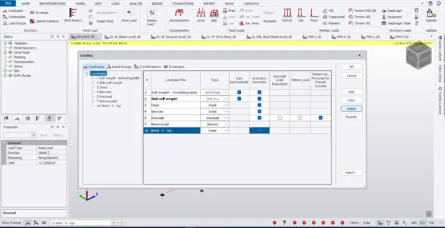
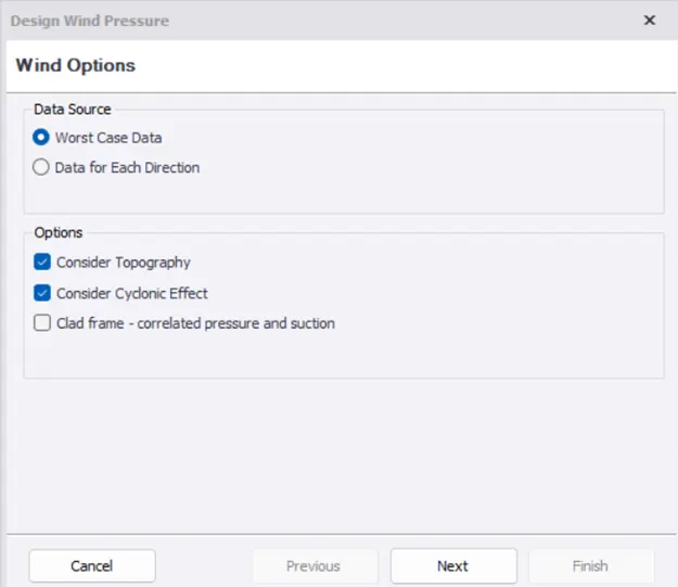
- Under wind load, select Wind wizard and under options tick Consider Cyclonic effect. Click on Next
- Provide the basic data
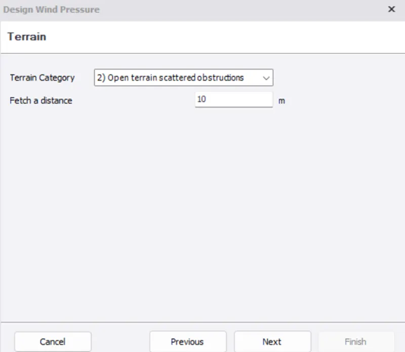
- Thus the wind loads are generated in 4 directions 0, 90 , 180 and 270 degrees
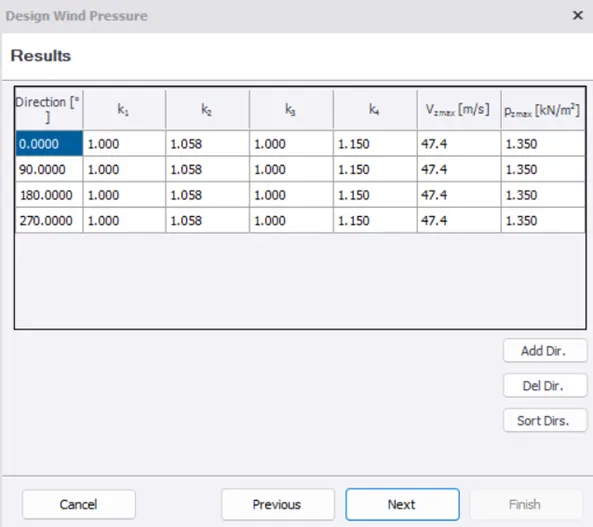
- Click on Next and finally click Finish
- Under Wind load, select Wind load cases to add various wind loads
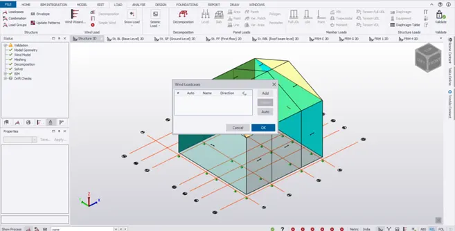
- Click on Add to add wind load cases for various directions 0, 90, 180 and 270 degrees with Cpi of +0.5 and -0.5
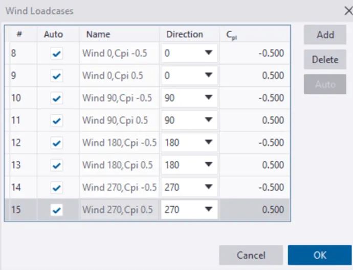
- Click on OK
- Hence the wind loads are generated
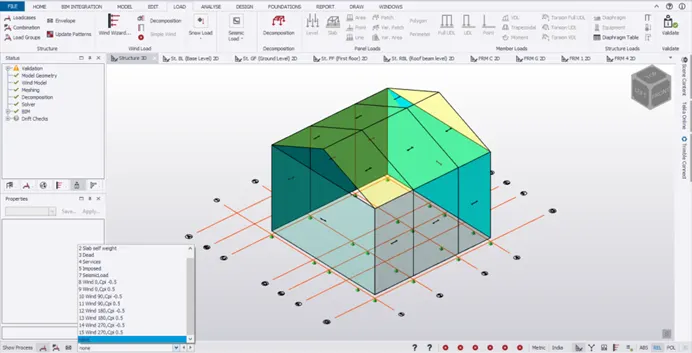
Result:
Thus the wind loads are generated using Wind Wizard option