To calculate the dead , live and wind load for RC residential structure and to apply them using TSD
Questions:
- Calculate dead load in design report based on IS code and apply dead load on the model:
- Finishes of 50mm.
- Slab thickness as per the design.
- Brick wall load.
- Roofing load.
- Calculate live load in design report based on IS code and apply dead load on the model.
- Generate manual wind loading in the design report based IS code as per the following input.
- Basic wind speed = 50m/s.
- Terrain category 2.
4. Based on the above calculation apply the loadings on the model.
Solutions:
1. Calculate dead load in design report based on IS code and apply dead load on the model:
- Finishes of 50mm.
- Slab thickness as per the design.
- Brick wall load.
- Roofing load.
Solution:
Manual Calculation of Dead Load :
AIM: To calculate the dead load in design report based on IS code and apply dead load on the model.
Manual Calculations:
Given Data:
Finishes - 50mm.
Slab as per design.
Brickwall - 150mm thickness.
Ceiling load - 0.3 kN/sq.m.
Roof load based on the Purlin size.
Slab load - Model slab in software.
Finishes Loading Calculations:
Finishes loading = Thickness of finishes * Density of Concrete.
Finishes loading = 0.05m * 24 kN/cu.m.
Finishes loading = 1.2 kN/sq.m.
Brickwall Load Calculations:
Brickwall with Cement Plaster = 225mm.
Unit weight of Brickwall = 20 kN/cub.m. (according to IS 875(Part 1), Table 1).
Floor Height (GF to FF) = 3.6m.
Brickwall loading = Unit weight of Brickwll * Brickwall with cement plaster thickness * Floor Height (GF to FF)
Brickwall loading = (0.225*20*3.6)
Brickwall Loading = 16.2 kN/m.
Floor Height (FF to Roof) = 3.6m.
Brickwall with Cement Plaster = 225mm.
Unit weight of Brickwall = 20 kN/cub.m. (according to IS 875(Part 1), Table 1).
Brickwall loading = Unit weight of Brickwll * Brickwall with cement plaster thickness * Floor Height (GF to FF)
Brickwall loading = (20*225*3.6)
Brickwall Loading = 16.2 kN/m.
Ceiling load = 0.3 kN/sq.m.
Roof load = 1.5 kN/sq.m.
PROCEDURE:
Apply dead loads that we just calculated on the model:
- First of all go to the TSD software, go to the OPEN option and open the previous assignment file in order to apply the dead loads on the previous model.
- Then after opening the file, go to the Load Tab option click on that just as shown in the below given image:

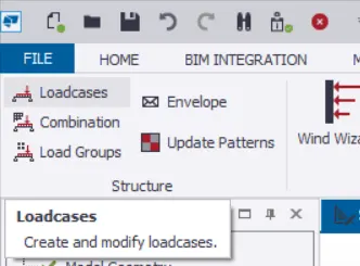
- There will be an option called Loadcases on the left hand side of the screen just click on that option just as shown in the below given image:
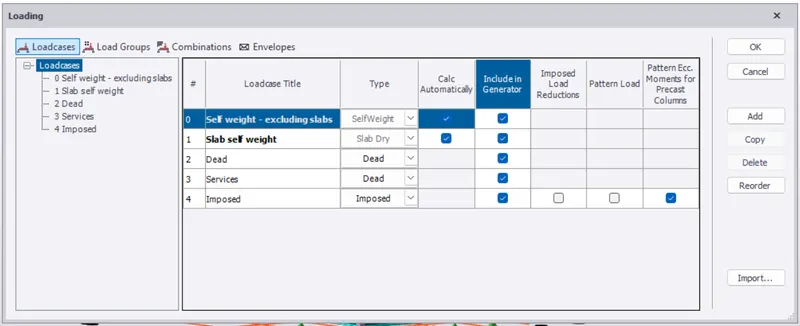
- After that there will be another dialouge box named as the load cases, in that dialouge box add more load cases according to our need just as shown in the below given image:
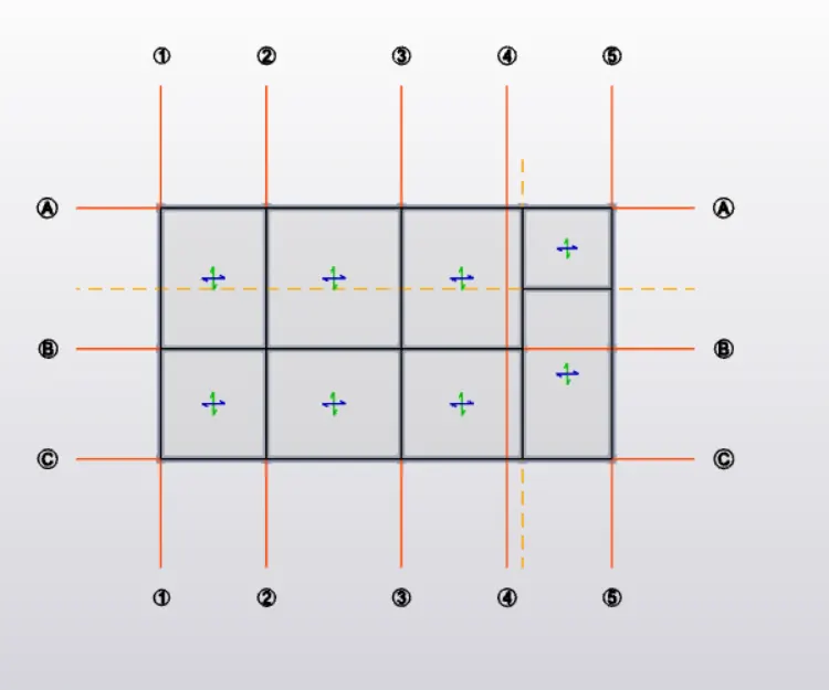
- Now select the levels where we want to add the loads and just as shown in the below given image:
Ground Floor:
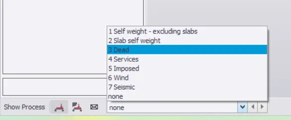
- Now go to the bottom left corner of screen where we will be selecting the loads. Just click on the option and select the Dead load option just as shown in the below given image:
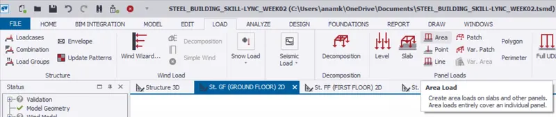
- And now go to the Load tab then there will be an option at the Panel loads tab Area just click on that option just as shown in the below given image:
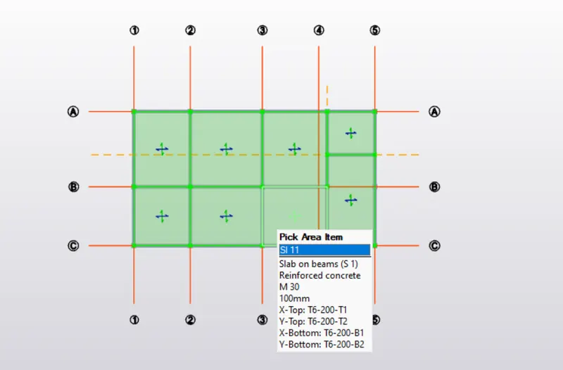
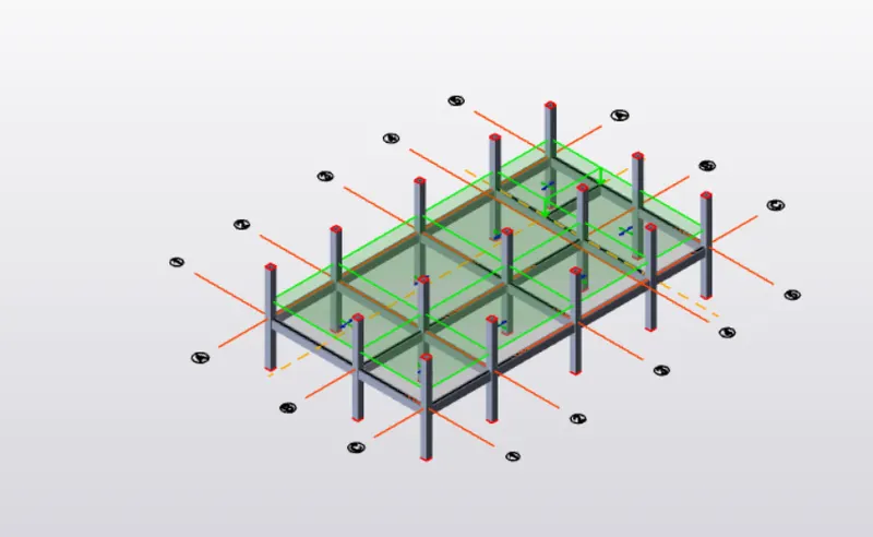
- Now change the load as the finish load and then apply the loadings just as shown in the below given image:
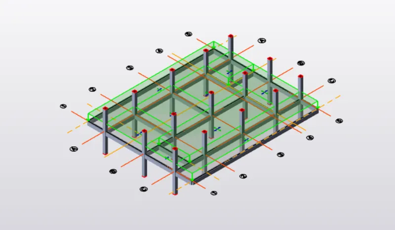
First floor:
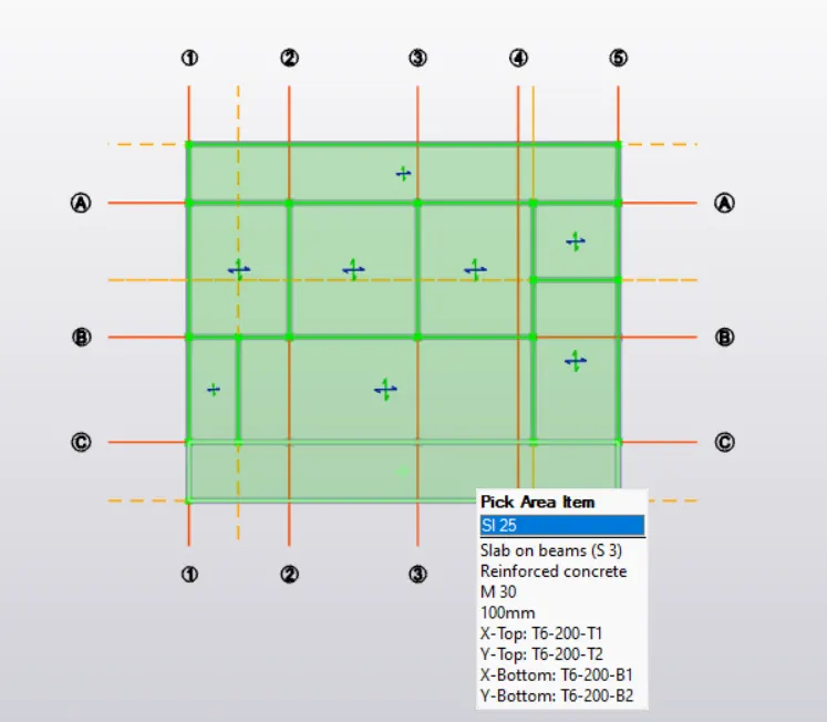
- Do the same procedure for the remaining floors. Below is the given image of the applied load on the second floor:
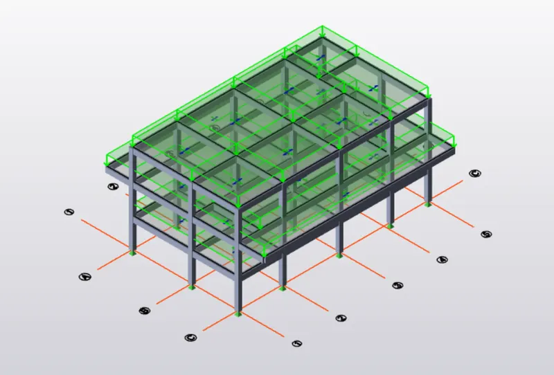
Roof:
- Below is the image after applying the loads:
Brickwall Load:
- And now we will be applying the brickwall loads on the model.
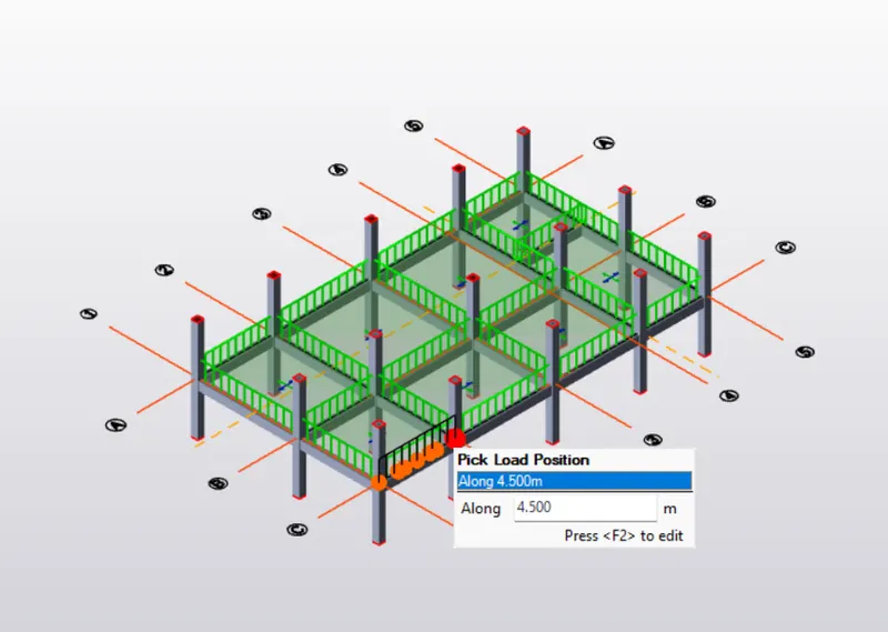
- And in order to do that go to the Loads tab option click on that after that there will be an option called Member load and in that member load there will be another option called Full UDL click on that just as shown in the below given image:

- Change the loadings and apply the loads on the floors just as shown in the below given image:
Ground Floor:
First Floor:
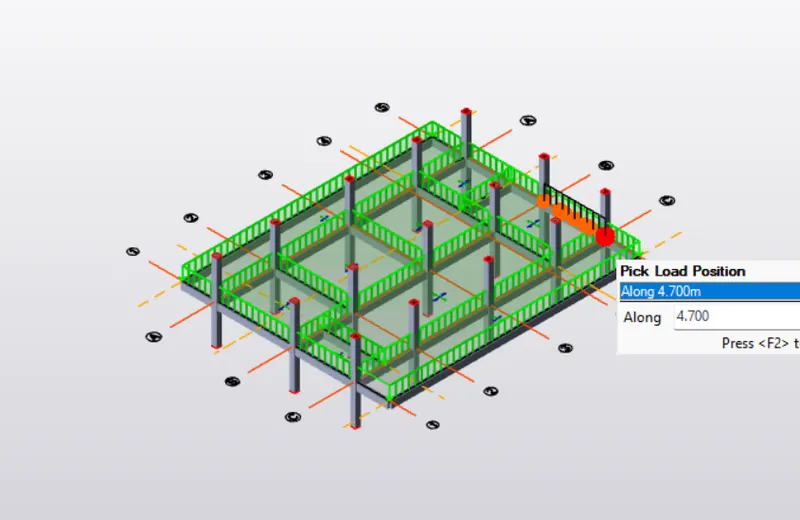
- Below is the image after applying the loads:
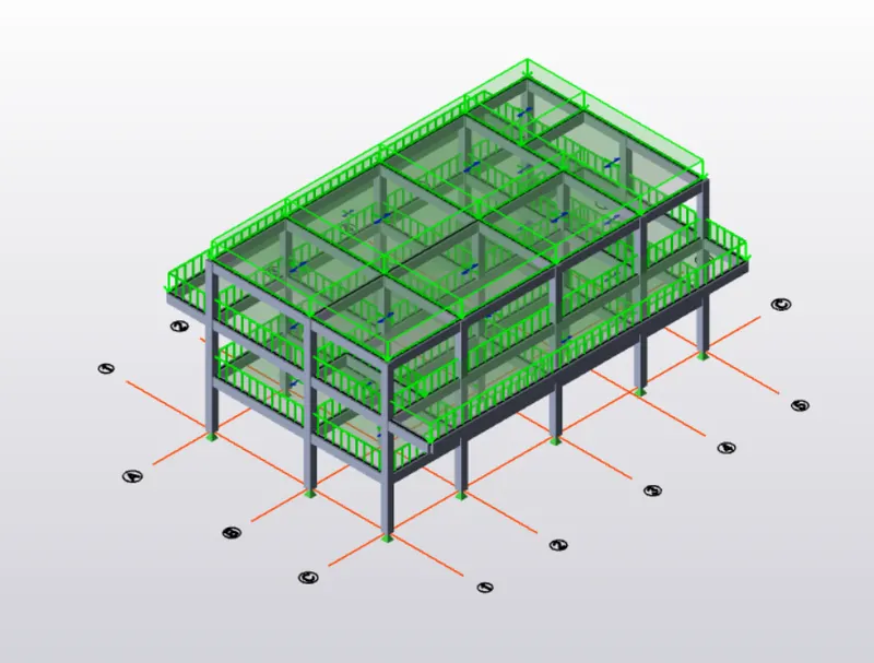
Roof Loadings:
Roof Loading = 1.5 kN/sq.m.
- Do the same procedure as above for applying the roof loadings to the structure.
- Below is the image after modelling the roof loads:
2. Calculate live load in design report based on IS code and apply live load on the model:
Solution:
AIM: To calculate the live load in design report based on IS code and apply live load on the model.
Manual Calculations:
From IS 875 Part:2 ; Table 1 we take the live loads as:
- Office room - 3 kN/sq.m.
- Conference room- 4 kN/sq.m.
- Toilet- 2 kN/sq.m.
- Corridor- 5 kN/sq.m.
- Reception - 3 kN/sq.m.
- Staircase- 3 kN/sq.m.
- Meeting room- 4 kN/sq.m.
- Store room- 5 kN/sq.m.
- Roof - 1.5 kN/sq.m.
- Equipment room - 4 kN/sq.m.
PROCEDURE:
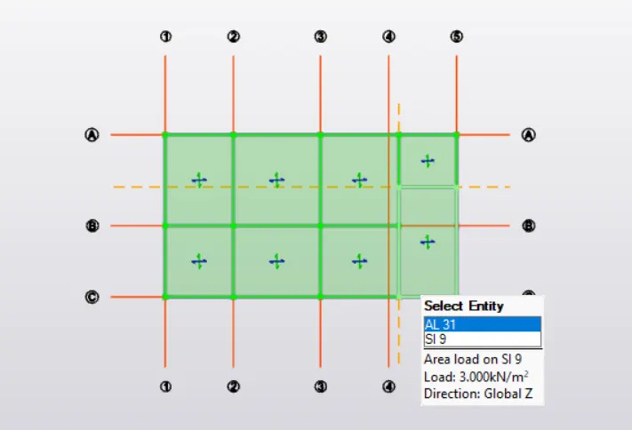
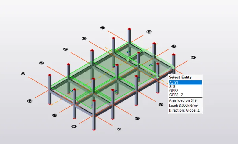
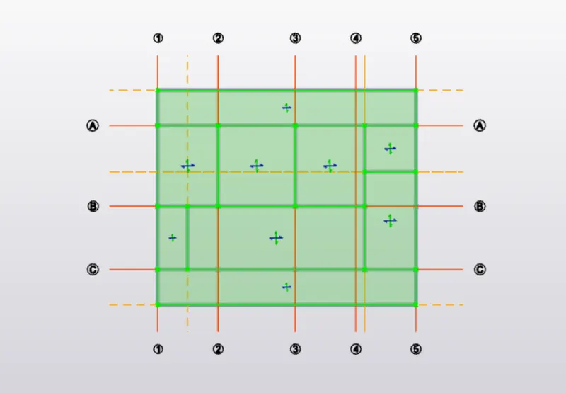
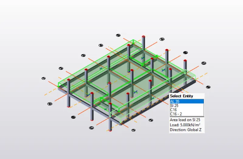
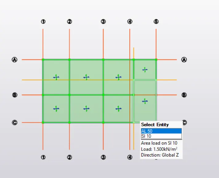
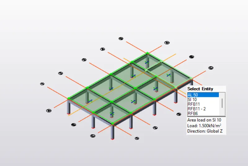
- To apply the Live load to the structure go to the Load tab then there will be an option at the Panel loads tab Area just click on that option just as shown in the below given image:
- Now change the load as the Live loads of different rooms according to the IS code 875 Part:2 and then apply the loadings just as shown in the below given image:
Ground Floor:
First Floor:
Roof:
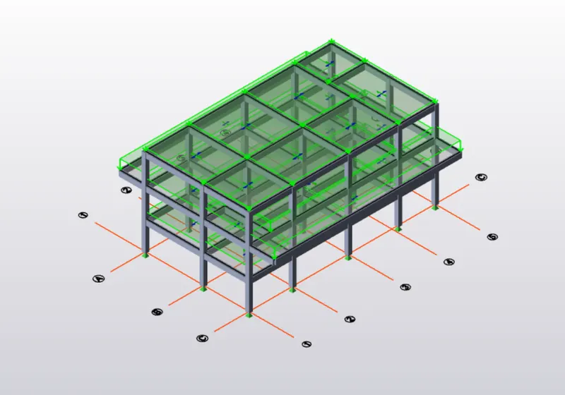
- Structure after applying the Imposed load, below is the image of the structure:
3. Generate manual wind loading in the design report based IS code as per the following input.
- Basic wind speed = 50m/s.
- Terrain category 2.
Solution:
AIM: To generate the manual wind loading in the design report based IS code according to the given input.
- Basic Wind Speed = 39 m/s.
- Terrain Category = 2.
Manual Calculations:
Given Data:
Basic wind speed = 50 m/s.
Terrain Category = 2.
Greater horizontal dimensions of structure, l = 19.225m.
Shorter side dimension, w = 10.70m.
Eaves level height of the structure, h = 16.8m.
According to the IS 875 Part-lll Clause 6.3.1:
Vb = Basic wind speed = 50 m/s. (According to the IS code 875 Part:2 Appendix:A).
Design Wind Speed, Vz = Vb*k1*k2*k3*k4.
Where,
k1 = Probability Factor.
k2 = Terrain height, structure factor.
k3 = Topography Factor.
k4 = Importance Factor for the cyclonic region.
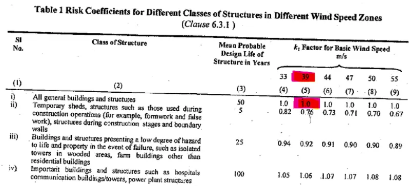
- According to IS 875 Part-lll: Table:1 the value of k1 = 1.0.
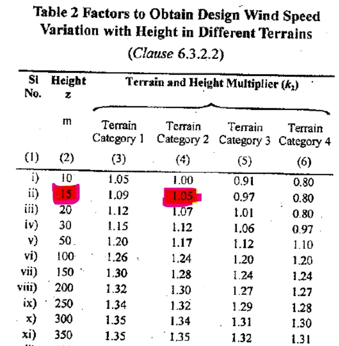
- According to IS 875 Part-lll, Table:2, the value of k2 = 1.05.
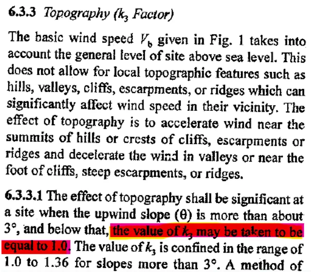
- According to IS 875 Part-lll, the value of k3 = 1.
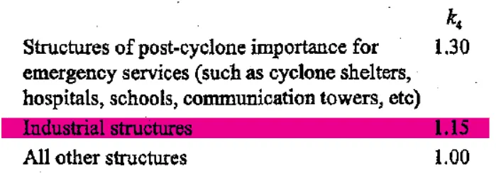
- According to IS Part-lll, the value of k4 = 1.15.
Calculations:
Wind Speed = 50 m/s.
Life Period of the structure = 50 years.
Terrain Category = 2.
Class Structure = A.
Step 1: Design Wind Speed and Design Wind Pressure:
- Design Wind Speed:
Design Wind Speed, Vz = Vb*k1*k2*k3*k4.
Design Wind Speed, Vz = 50*1.0*1*1*1.15.
Design Wind Speed, Vz = 57.5 m/s.
Design Wind Pressure, Pz = 0.6*`Vz^2`
Pz = 0.6*`(57.5)^2`
Design Wind Pressure, Pz = 1983.75 N/sq.m.
Design Wind Pressure, Pz = 1.984 kN/sq.m.
Roof angle = 0 degree.
Internal pressure co-efficient = 0.50 (Upto 20% opening).
Internal pressure co-efficient = +0.50 (Upto 20% opening).
Step 2 : Ratio of wall and roof co-efficient:
Wall:
l/w = 1.79.
h/w = 1.5.
Roof:
h/w = 0.86.
Wind directions X:
| Wind Load along +X-direction (Face A): | ||
| Cpi + | Cpi - | |
| upto 10m | upto 10m | |
| External Pressure Co-efficient,Cpe | -0.5 | -0.5 |
| Internal Pressure Co-efficient,Cpi | 0.5 | -0.5 |
| Net-Pressure,Cp = Cpe-Cpi | -1.0 | 0.0 |
| Design wind pressure on the wall,Pz (kN/sq.m) | 1.984 | 1.984 |
| Loading to be applied on the wall, Cp x Pz | -1.984 | 0.0 |
| K2 factor from table 2:1.05 | -2.08 | 0.0 |
| Wind Load along +X-direction (Face B): | ||
| Cpi + | Cpe - | |
| upto 10m | upto 10m | |
| External Pressure Co-efficient,Cpe | -0.5 | -0.5 |
| Internal Pressure Co-efficient,Cpi | 0.5 | -0.5 |
| Net-Pressure,Cp = Cpe-Cpi | -1.0 | 0.0 |
| Design wind pressure on the wall,Pz (kN/sq.m) | 1.984 | 1.984 |
| Loading to be applied on the wall, Cp x Pz | -1.984 | 0.0 |
| K2 factor from table 2:1.05 | -2.08 | 0.0 |
| Wind Load along +X-direction (Face C): | ||
| Cpi + | Cpi - | |
| upto 10m | upto 10m | |
| External Pressure Co-efficient,Cpe | 0.7 | 0.7 |
| Internal Pressure Co-efficient,Cpi | 0.5 | -0.5 |
| Net-Pressure,Cp = Cpe-Cpi | 0.2 | 1.2 |
| Design wind pressure on the wall,Pz (kN/sq.m) | 1.984 | 1.984 |
| Loading to be applied on the wall, Cp x Pz | 0.3968 | 2.38 |
| K2 factor from table 2:1.05 | 0.417 | 2.5 |
| Wind Load along +X-direction (Face D): | ||
| Cpi + | Cpi - | |
| upto 10m | upto 10m | |
| External Pressure Co-efficient,Cpe | -0.1 | -0.1 |
| Internal Pressure Co-efficient,Cpi | 0.5 | -0.5 |
| Net-Pressure,Cp = Cpe-Cpi | -0.6 | 0.4 |
| Design wind pressure on the wall,Pz (kN/sq.m) | 1.984 | 1.984 |
| Loading to be applied on the wall, Cp x Pz | -1.2 | 0.8 |
| K2 factor from table 2:1.05 | -1.26 | 0.84 |
| Wind directions Y: | ||
| Wind Load along Y-direction (Face A): | ||
| Cpi + | Cpi - | |
| upto 10m | upto 10m | |
| External Pressure Co-efficient,Cpe | 0.7 | 0.7 |
| Internal Pressure Co-efficient,Cpi | 0.5 | -0.5 |
| Net-Pressure,Cp = Cpe-Cpi | 0.2 | 1.2 |
| Design wind pressure on the wall,Pz (kN/sq.m) | 1.984 | 1.984 |
| Loading to be applied on the wall, Cp x Pz | 0.4 | 2.38 |
| K2 factor from table 2:1.05 | 0.42 | 2.5 |
| Wind Load along Y-direction (Face B): | ||
| Cpi+ | Cpi- | |
| upto 10m | upto 10m | |
| External Pressure Co-efficient,Cpe | -0.3 | -0.3 |
| Internal Pressure Co-efficient,Cpi | 0.5 | -0.5 |
| Net-Pressure,Cp = Cpe-Cpi | -0.8 | 0.2 |
| Design wind pressure on the wall,Pz (kN/sq.m) | 1.984 | 1.984 |
| Loading to be applied on the wall, Cp x Pz | -1.587 | 0.4 |
| K2 factor from table 2:1.05 | -1.667 | 0.42 |
| Wind Load along Y-direction (Face C): | ||
| Cpi+ | Cpi- | |
| upto 10m | upto 10m | |
| External Pressure Co-efficient,Cpe | -0.7 | -0.7 |
| Internal Pressure Co-efficient,Cpi | 0.5 | -0.5 |
| Net-Pressure,Cp = Cpe-Cpi | -1.2 | -0.2 |
| Design wind pressure on the wall,Pz (kN/sq.m) | 1.984 | 1.984 |
| Loading to be applied on the wall, Cp x Pz | -2.38 | -0.4 |
| K2 factor from table 2:1.05 | -2.5 | -0.42 |
| Wind Load along Y-direction (Face D): | ||
| Cpi+ | Cpi- | |
| upto 10m | upto 10m | |
| External Pressure Co-efficient,Cpe | -0.7 | -0.7 |
| Internal Pressure Co-efficient,Cpi | 0.5 | -0.5 |
| Net-Pressure,Cp = Cpe-Cpi | -1.2 | 0.2 |
| Design wind pressure on the wall,Pz (kN/sq.m) | 1.984 | 1.984 |
| Loading to be applied on the wall, Cp x Pz | -2.38 | 0.4 |
| K2 factor from table 2:1.05 | -2.5 | 0.42 |
4.Based on the above calculation apply the loadings on the model.
Solution:
AIM: To apply the calculated wind loads manually calculated loads on the model in the TSD software.
PROCEDURE:
Step_01:
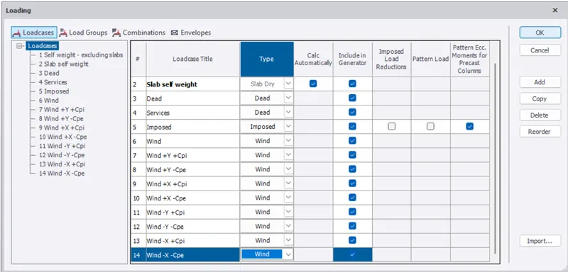
- Below are the combinations for the wind loads that we are going to apply on the model.
Wall Loadings (Face A, B, C and D):
- Y +Cpi.
- Y -Cpi.
- -Y +Cpi.
- -Y -Cpi.
Wall Loadings (Face A, B, C and D):
- X +Cpi.
- X -Cpi.
- -X +Cpi.
- -X -Cpi.
- Now open the Tekla Model our previous assignment in the software.
- Now go to the Load option just click on that just as shown in the below given image:

- Now there will be an option in the Load ribbon at the left side of the screen as Load combinations just click on that option just as shown in the below given image:
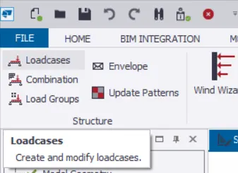
- After that there will be another dialouge box named as the Loadings opens as shown in the below given image:
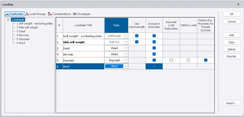
- Now in the above dialouge box add the wind load combinations just as shown in the below given image:
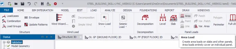
- Now we will be applying the wind load cases and to apply the wind loads in the model go to the load ribbons and then in that ribbon there will be an option in the Panel Loads there will be an option called Area just click on that option just as shown in the below given image:
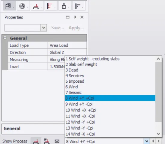
- Now select the frame and select the combination which is present at the bottom of the workspace just as shown in the below given image:
- Wind Load +Y +Cpi (Face A):
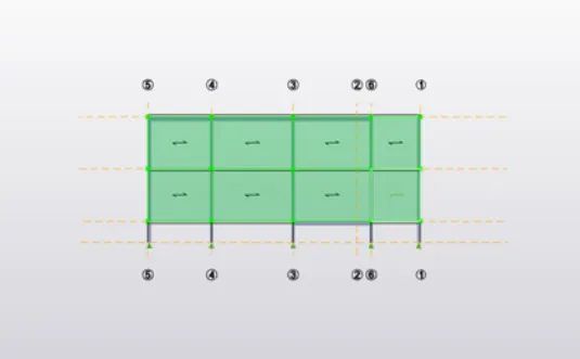
- Wind Load +Y-Cpi (Face A):
- Wind Load +Y+Cpi (Face B):
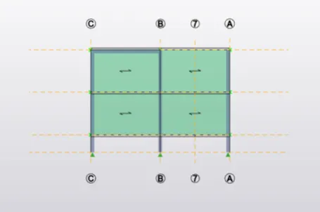
- Wind Load +Y-Cpi (Face B):