To calculate the dead , live and wind load for RC residential structure and to apply them using TSD
Calculate dead load in design report based on IS code and apply dead load on the model
- Finishes of 50mm
- Slab thickness as per the design
- Brick wall load
- Roofing load
AIM- To calculate the dead load in design report based on IS code and apply dead load on the model.
PROCEDURE :
- Finishes of 50mm
- Slab thickness as per the design
- Brick wall load
- Roofing load
Finish load (Dead Load) = 0.05 x 24 = 1.2 kN/m2 (Area Load)
Slab Load to be applied in software
For Brick wall load, from GF to FF
Brick wall with cement plaster thickness = 230 mm = 0.23 m
Unit weight = 20kN/m3 [As per IS: 875 (part-1), Table- 1]
Floor height = 3 m
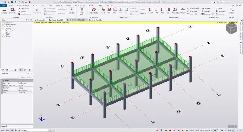
Hence, Brick wall Load= 20 x 0.23 x 3 = 13.8 kN/m
Roofing Load = 1.5 kN/m2
Load is to be applied to the previous challenge model.
- Create Load Cases by going to the Load tab. Add the above loadings.
- Now go to GF, select dead loadcase below. Now apply the above dead load value of 1.2 kN/m2 using area loading.
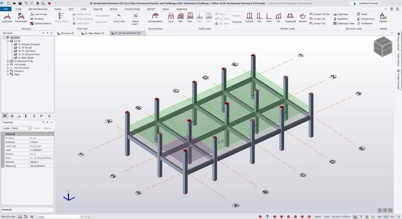
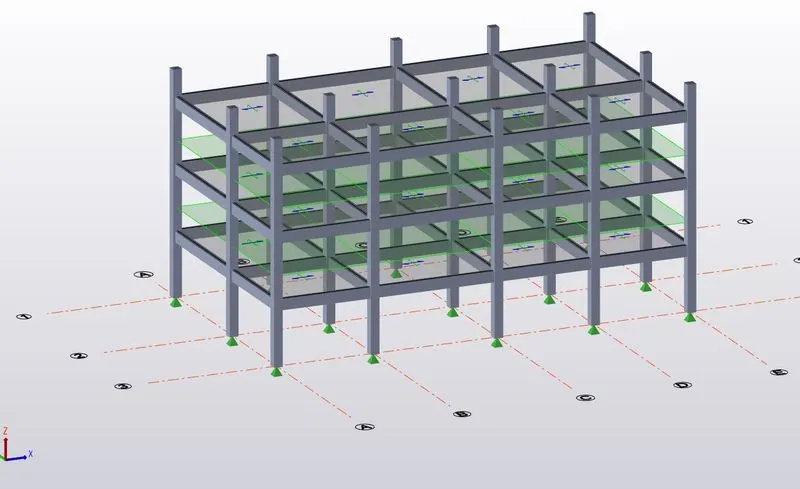
- The loads are automatically copied to the First Floor. As we can see in 3D.
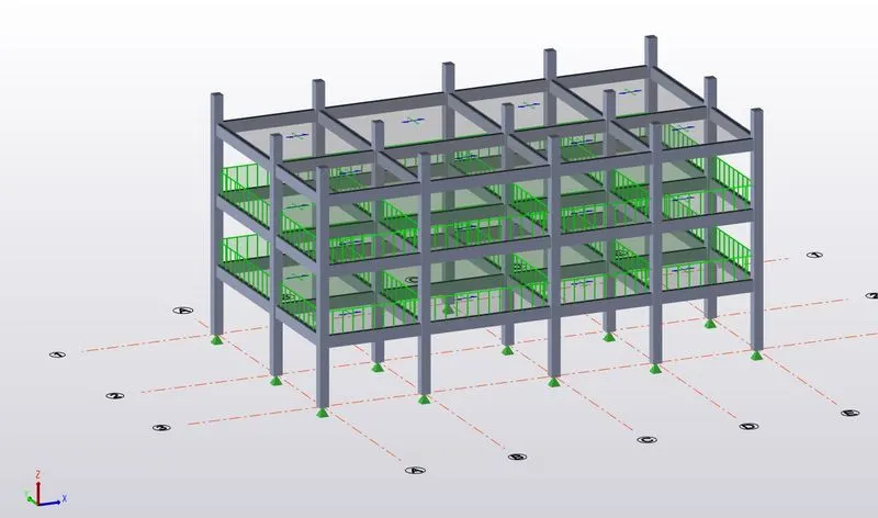
- Now, apply Brick Wall Load (member load) of 13.8 kN/m to all the beams in GF and the loads will be copied to FF in similar way.
- 3D view is shown below.
- Apply roof load to RF
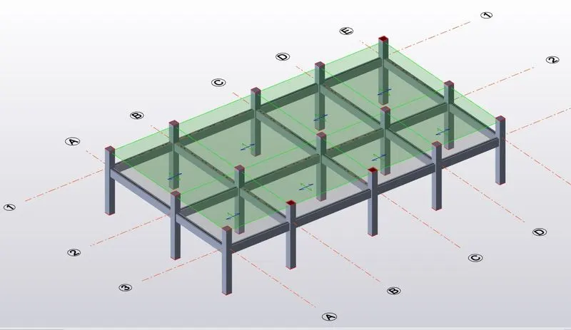
RESULT : 3D view of the whole structure after calculating and applying all dead loads.
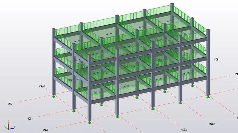
Calculate live load in design report based on IS code and apply the load on the model
AIM : To Calculate live load in design report based on IS code and apply the load on the model.
PROCEDURE :
As per IS 875 (part 3),The given live loads are:
- Office= 3 kN/m2
- Reception= 3 kN/m2
- Meeting room/conference room= 4 kN/m3
- Equipment room = 10 kN/m2
- Toilets= 2 kN/m2
- Store room= 5 kN/m2
- Staircase =3 kN/m2
- Lobby =3 kN/m2
- Corridor= 4 kN/m2
- Roof (accessible) = 1.5 kN/m2
Load applied on model :
- Apply the Imposed load
- Select the Imposed load on bottom of the screen
- As per the IS 875 rules, the imposed load to be applied as per the Table
- First go to the Area load under the modal tab
- Finally apply the load
GROUND FLOOR-
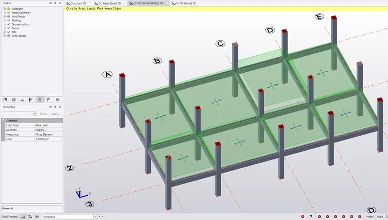
FIRST FLOOR-
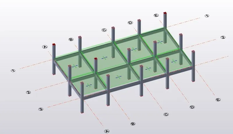
ROOF FLOOR-
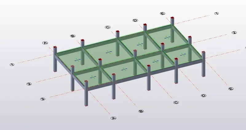
3D View with Live/Imposed load
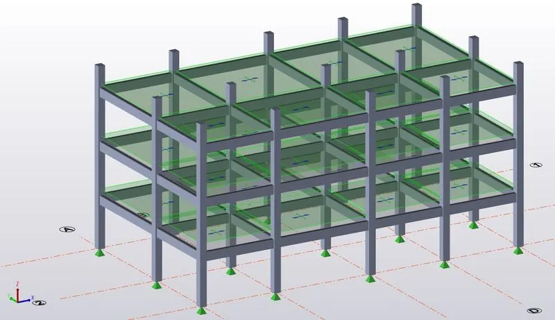
RESULT : As per the question to Calculate live load in design report based on IS code and apply the load on the model is completed.
Generate manual wind loading in the design report based IS code as per the following input
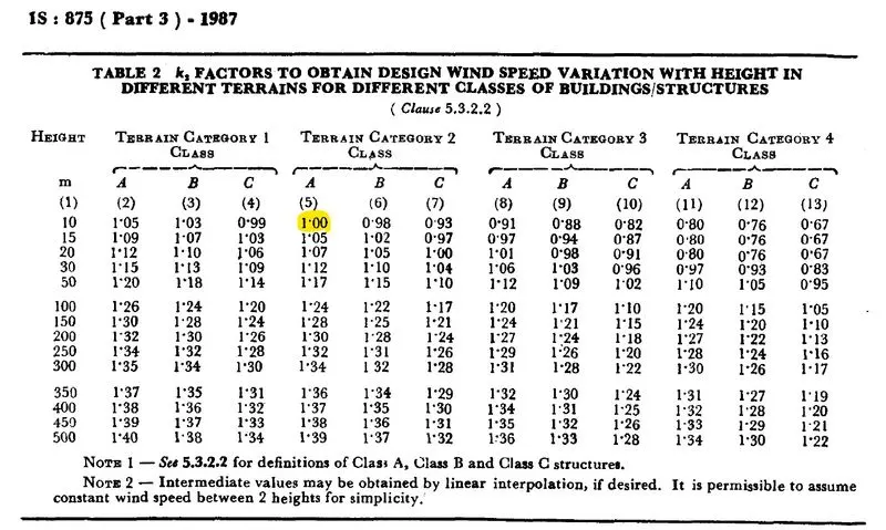
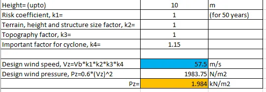
- Basic wind speed = 50m/s
- Terrain category 2
AIM : To Generate manual wind loading in the design report based IS code as per the following input
PROCEDURE :
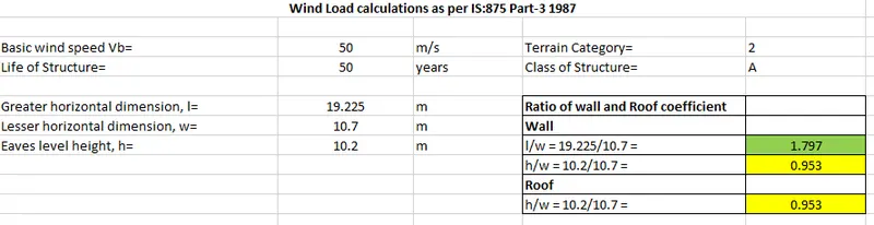
Given :
- Basic wind speed = 50m/s
- Terrain category 2
- Total length of the building (l) = 19.225m
- Total width of the building (w) = 10.7m
- Total height of the building (h) = 10.2m
- Class of the structure = Class A
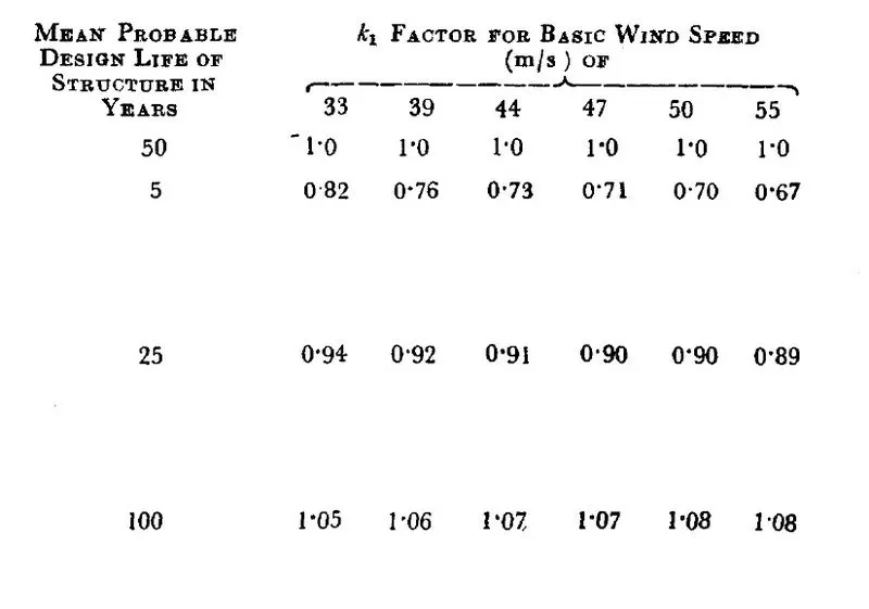
- Life of the structure = 50 Years
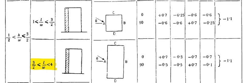
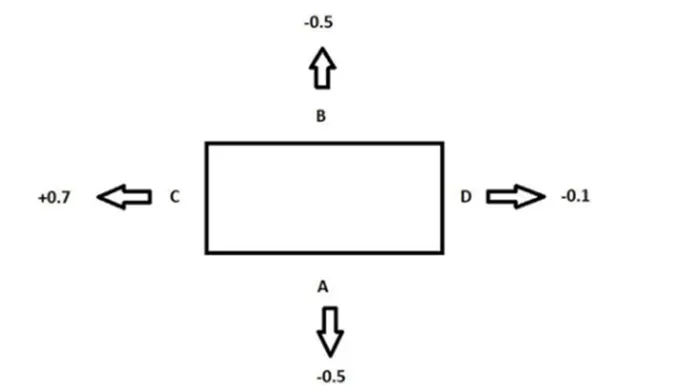
- l/w = (19.225/10.700) = 1.79
- h/w = (10.2/10.7) = 0.95
As per the IS 875 Part 3, Table 4. External coefficient pressure Cpe,
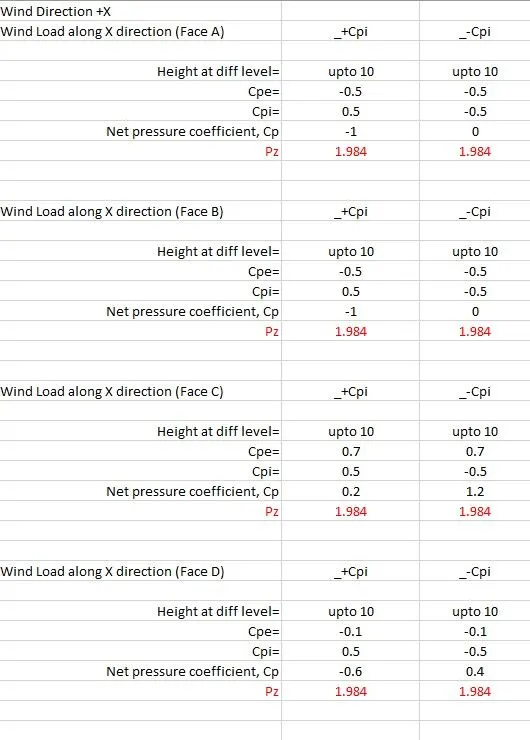
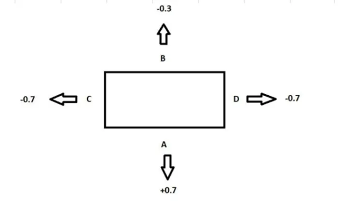
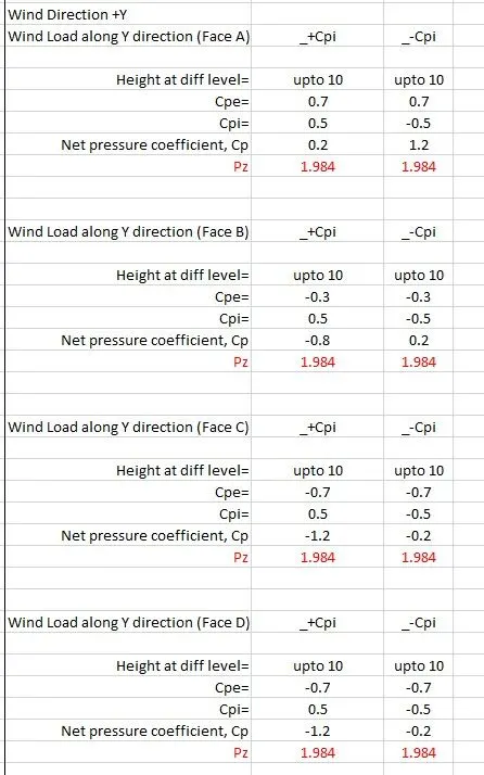
Result: All calculations of wind load are herby done.
Based on the above calculation apply the loadings on the model
AIM : Based on the above calculation apply the loadings on the model
PROCEDURE :
Load applied on model :
- Create wind load cases.
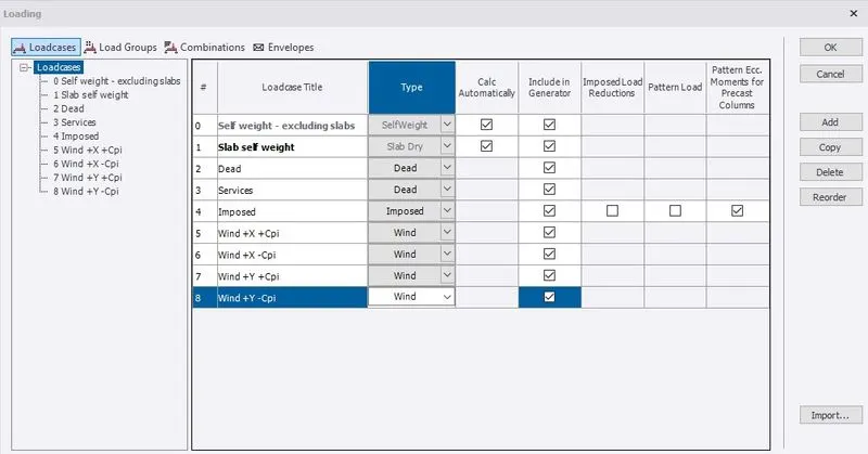
- Before putting the loads we need to create Wall panels.
- Create wall panels from every frame on which wind loads are to be applied.
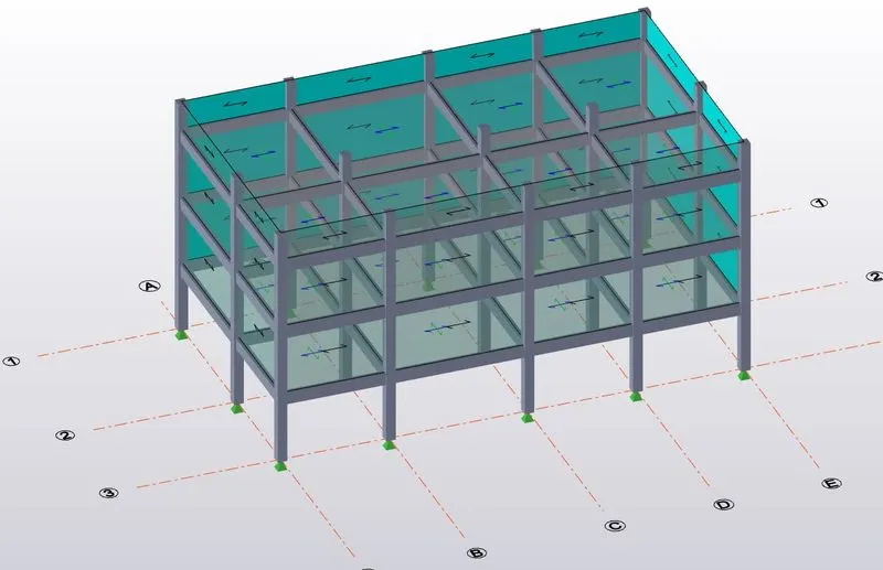
- Next, create Frames.
- To create frames go to frame from Model tab and then click on the grid lines. The frames are created as follows.
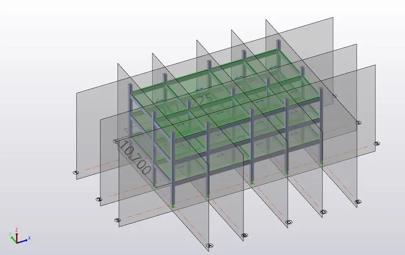
- Select frames from structure tab and
- Next set the wind load on bottom of the screen
- And go to the area load
- set the global y on the general box
- Then apply the loads on the wall panel
- Use the above calculations to apply the load
- Use the frame option select the frame 1 and 3 , frame A and E
- Then use the x and y direction
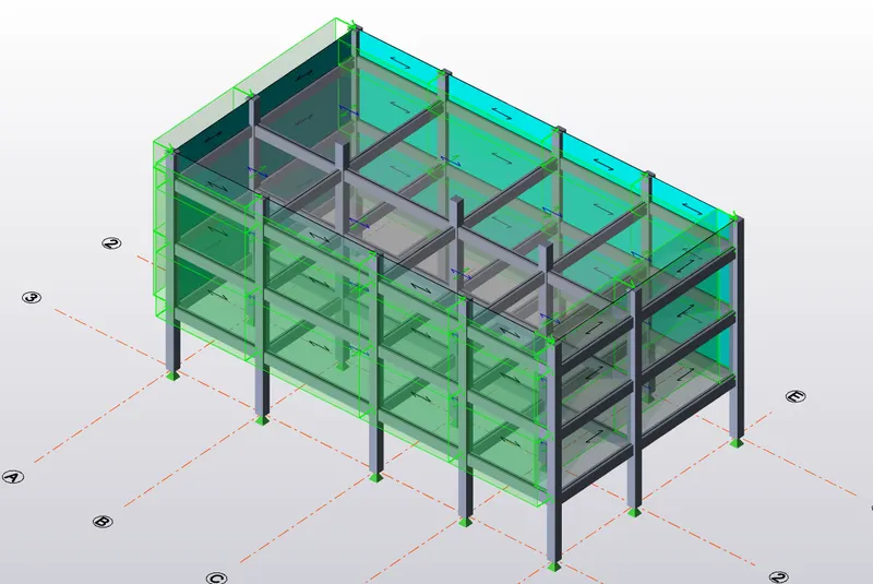
- select and use the (Wind + X + Cpi), (Wind + X - Cpi), (Wind + Y + Cpi), (Wind + Y - Cpi)
- Apply all direction of the load as been shown below
Wind +X+Cpi
Wind +X -CPi
Wind +Y +Cpi
Wind +Y -Cpi
Validate the structure. No errors.
Result: All wind loading are applied to the model. The wind load calculation excel file and the Tekla Structural Designer file is attached for reference.