To calculate the dead , live and wind load for RC residential structure and to apply them using TSD
ANSWER 1
- Finishes of 50mm
- Slab thickness as per the design
- Brick wall load
- Roofing load
Finish load = 0.5*24=1.2KN/m^2
Slab load will be generated within the software
Brick wall + cement plaster thickness 230mm
Brick wall load = GL-1st floor-0.23*20*3.2=14.72KN/m^3
Same for 1st floor roof level
Roof level = 0.155*0.9*20=2.79KN/m^3
Roof load - finish load - 1.2KN/m^3
ANSWER 2
As per IS 875: part 3, live load for RC office building are
- Office=3KN/m^2
- Reception= 3KN/m^2
- Meeting room/conference room = 4KN/m^2
- Equipment room = 10KN/m^2
- Toilet = 2KN/m^2
- Store room= 5KN/m^2
- Staircase = 4KN/m^2
- Lobby = 3KN/m^2
- Cooridor= 4KN/m^2
- Roof =1.5KN/m^2
ANSWER 3
AS per IS 875 part 3
Basic parameters
- Basic wind speed = 50m/s
- Terrain category 2
- Probabe design period of building - 50years
- Class of structure A
Dimension of building
- Greater horizontal dimension = 19.225m
- Lesser horizontal dimension = 107m
- Height of building= 6.4m
- Width of frame 1, Grid A to B-6m
Ratio of wall and roof-coefficient
Wall - L/w = 1.8
Wall - h/w = 0.6
Roof - h/w = 0.6
Topography factor, K3-1
Risk co-efficient, K1-1
up to 10m height, terrain factor(k2)-1
Important factor for cyclonic, k4-1.15
Design wind speed, V2=Vb*K1*K2*K3*K4=39*1*1*1*1.5=44.85m/s
Design wind pressure, Pz=0.6*vz^2/1000= 0.6*44.85/1000=1.207KN/m^2
Internal pressure coefficient= 0.5
Internal pressure coefficient = -0.5
Wind load calculation
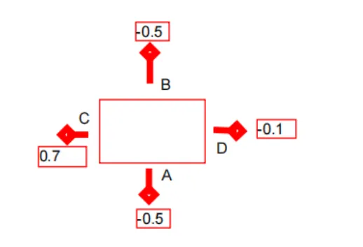
Wind load action along X direction
| +Cpi | -Cpi | |
| Height at a different level | <=10m | |
|
External pressure coefficient Cpe |
0.5 | 0.5 |
| Internal pressure coefficient Cpi | -0.5 | 0.5 |
| Net pressure coefficient, Cp | -1 | 0 |
| Design wind pressure for wall | 1.207 | 1.207 |
| Loading to be applied on the wall | -1.207 | 0 |
wind load along X direction (Face B)
| +Cpi | -Cpi | |
| Height at a different level | <=10m | |
|
External pressure coefficient Cpe |
-0.5 | -0.5 |
| Internal pressure coefficient Cpi | 0.5 | -0.5 |
| Net pressure coefficient, Cp | -1 | 0 |
| Design wind pressure for wall | 1.207 | 1.207 |
| Loading to be applied on the wall | -1.207 | 0 |
wind load along Y direction (Face C)
| +Cpi | -Cpi | |
| Height at a different level | <=10m | |
|
External pressure coefficient Cpe |
0.7 | 0.7 |
| Internal pressure coefficient Cpi | 0.5 | -0.5 |
| Net pressure coefficient, Cp | 0.2 | 01.2 |
| Design wind pressure for wall | 1.207 | 1.207 |
| Loading to be applied on the wall | 0.24 | 1.45 |
wind load along X direction (Face D)
| +Cpi | -Cpi | |
| Height at a different level | <=10m | |
|
External pressure coefficient Cpe |
-0.1 | -0.1 |
| Internal pressure coefficient Cpi | 0.5 | -0.5 |
| Net pressure coefficient, Cp | -0.6 | 0.4 |
| Design wind pressure for wall | 1.207 | 1.207 |
| Loading to be applied on the wall | -0.72 | 0.483 |
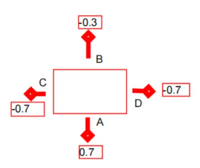
wind load along X direction (Face A)
| +Cpi | -Cpi | |
| Height at a different level | <=10m | |
|
External pressure coefficient Cpe |
0.7 | 0.7 |
| Internal pressure coefficient Cpi | 0.5 | -0.5 |
| Net pressure coefficient, Cp | 0.2 | 1.2 |
| Design wind pressure for wall | 1.207 | 1.207 |
| Loading to be applied on the wall | 0.24 | 1.45 |
Wind load acting along Y- direction
| +Cpi | -Cpi | |
| Height at a different level | <=10m | |
|
External pressure coefficient Cpe |
-0.3 | -0.3 |
| Internal pressure coefficient Cpi | 0.5 | -0.5 |
| Net pressure coefficient, Cp | -0.8 | 0.2 |
| Design wind pressure for wall | 1.207 | 1.207 |
| Loading to be applied on the wall | -0.96 | 0.24 |
Wind load acting along the Y direction (Face C)
| +Cpi | -Cpi | |
| Height at a different level | <=10m | |
|
External pressure coefficient Cpe |
-0.7 | -0.7 |
| Internal pressure coefficient Cpi | 0.5 | -0.5 |
| Net pressure coefficient, Cp | -1.2 | -0.2 |
| Design wind pressure for wall | 1.207 | 1.207 |
| Loading to be applied on the wall | -1.45 | 0.25 |
Wind load acting along y-direction (Face D)
| +Cpi | -Cpi | |
| Height at a different level | <=10m | |
|
External pressure coefficient Cpe |
-0.7 | -0.7 |
| Internal pressure coefficient Cpi | 0.5 | -0.5 |
| Net pressure coefficient, Cp | -1.2 | -0.2 |
| Design wind pressure for wall | 1.207 | 1.207 |
| Loading to be applied on the wall | -1.45 | -0.24 |
ANSWER 4
AIM
Based on above calculation apply the loadings on the model
PROCEDURE
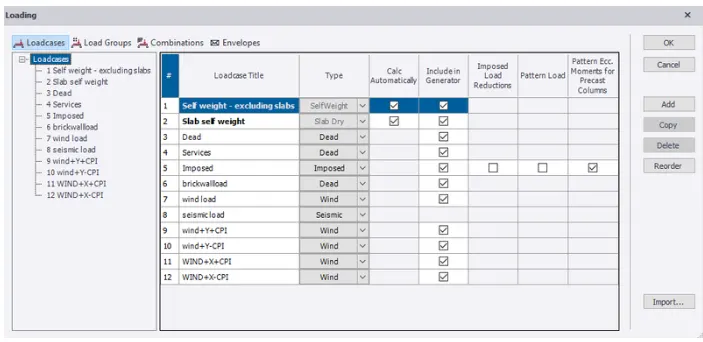
- Go to load toolbar, define load cases
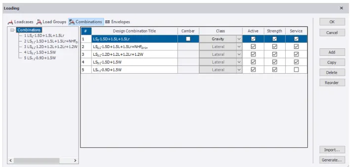
- Generate load combinations
- For dead load, finish load- select area load and enter 1.2KN/m^2
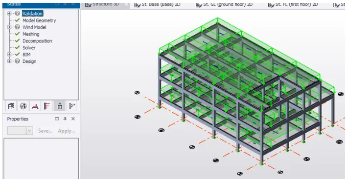
- For brickwall load, select full UDL/point UDL and enter the respective value
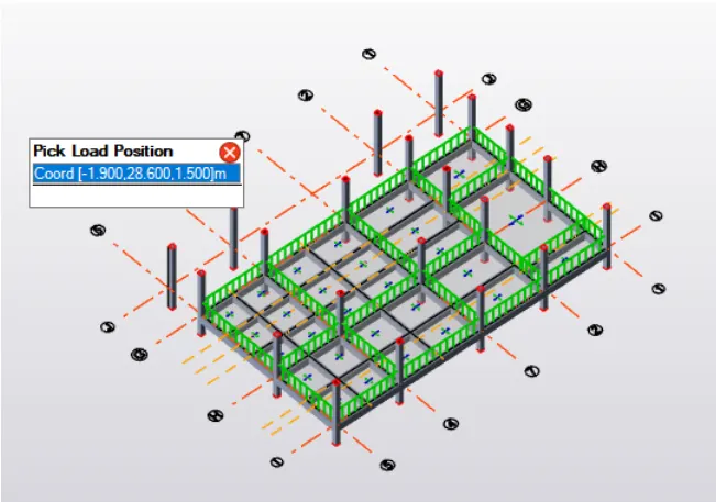
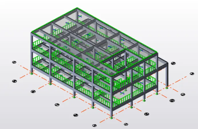
- For live load, select area load and enter value as per IS code book
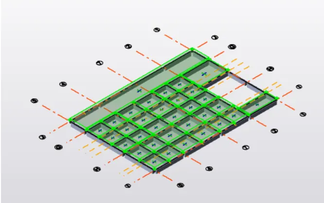
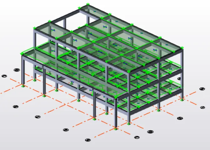
- For wind load, first add wall panels
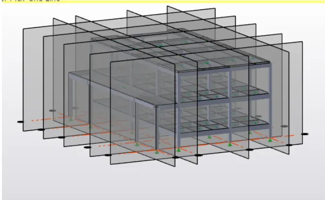
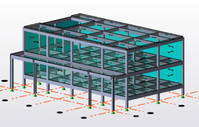
- Select area load and respective direction of building face, enter the value an select on wall panel
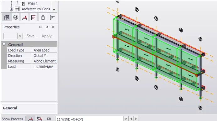
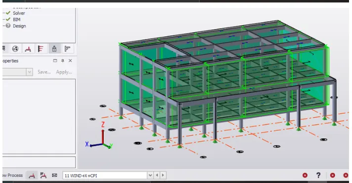
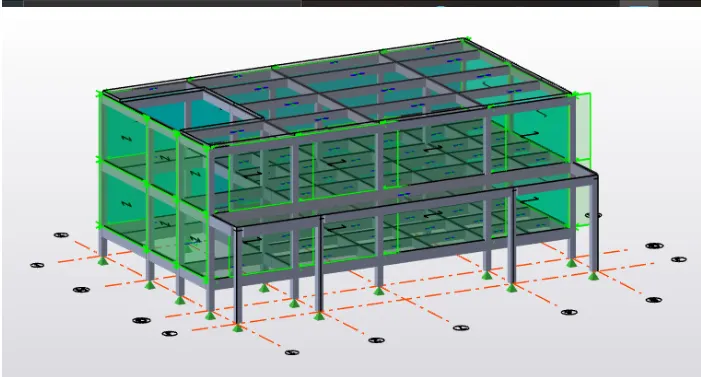
RESULT
The calculated loads are applied on the model successfully