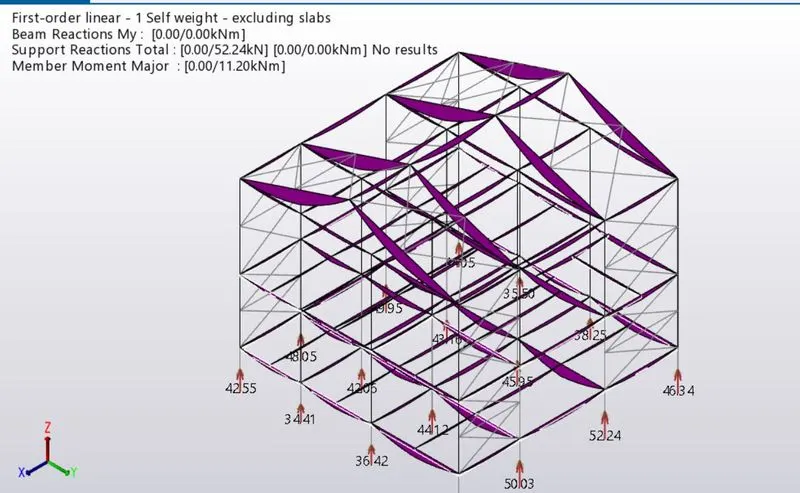
To Analysis and Design of Steel Structures using TSD
Questions.
- Summarize your study for the bending moment, shear force and deflection diagrams for the elements of the model.
- Based on the analysis design the members and outline the thought process in selecting the member sizes along with the foundation design.
Solutions:
1. Summarize your study for the bending moment, shear force and deflection diagrams for the elements of the model.
Solution:
AIM: To summarize our study for the bending moment, shear force and the deflection diagrams for the elements of the model.
PROCEDURE:
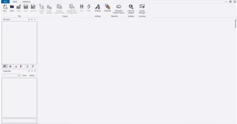
- First of all we need to open the TSD software as shown in the below given image:
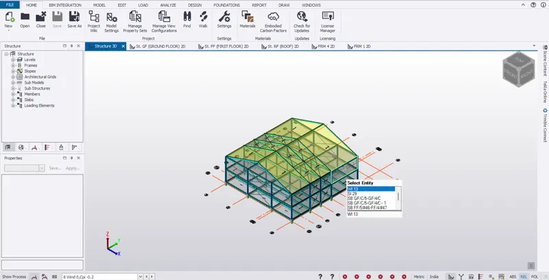
- Now we will be opening the previous assignment on which we were working as shown in the below given image:
- Now go to the Analyze tab just click on that option just as shown in the below given image:

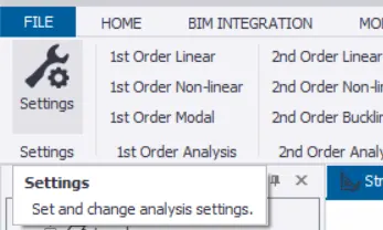
- Now in the Analyze tab there will be an option called Settings just as shown in the below given image:
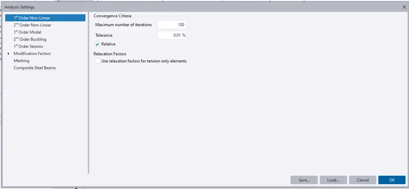
- After clicking on the option Settings then there will be another dialouge box named as the Analysis settings and in that dialouge box there will be an option Convergence Criteria and the Relaxation factor fill these factors just as shown in the below given image:
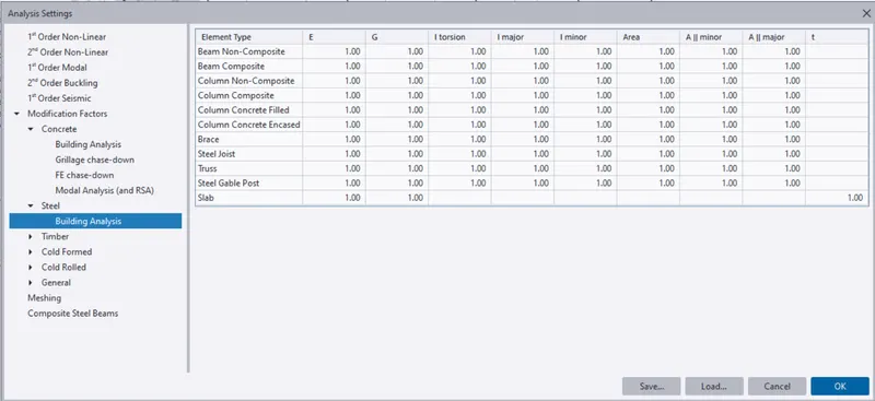
- After that in the same dialouge box there will be another option named as the Modification Factors just click on that option after that there will be another option in the modification factor named as the Steel and then there will be another one option Building analysis click on that and make sure the factor must be 1.0 just as shown in the below given image:
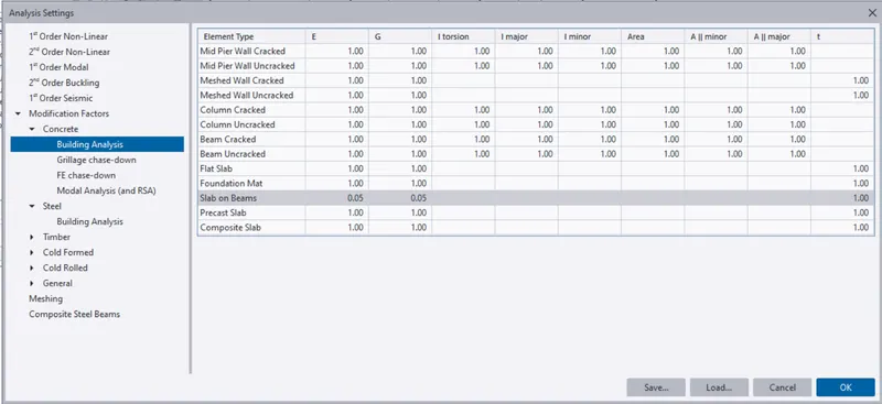
- Now there will be another option in Modification factor Concrete in that and then there will be another one option Building analysis click on that and make sure the factor must be 1.0 just as shown in the below given image:
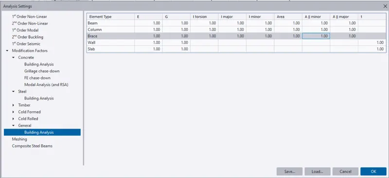
- Again there will be another option in Modification factor General in that and then there will be another one option Building analysis click on that and make sure the factor must be 1.0 just as shown in the below given image:
Bending Moment:
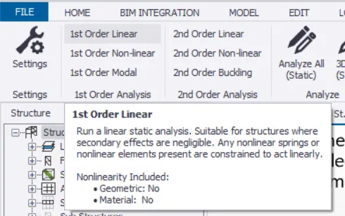
- Now in the analyze tab there will be an option called 1st Order Linear just click on that option just as shown in the below given image:
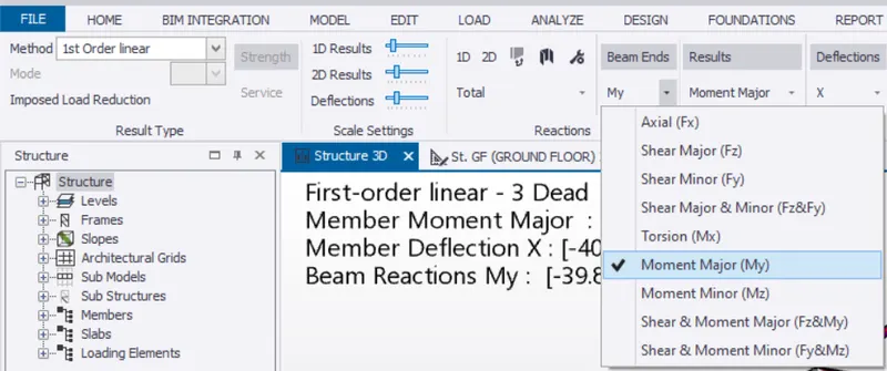
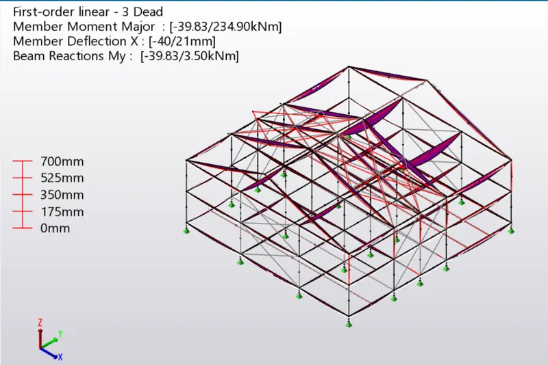
- Now after that there will be an option called Beam Ends just click on that option then there will be a drop-down list and in that list there will be an option called Moment Major (My) just click on that option just as shown in the below given image:
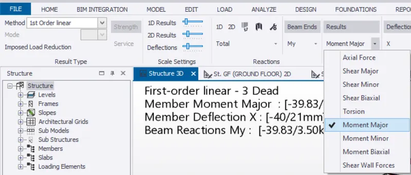
- After that in the Analyze tab there will be another option called Results just click on that option then there will be a drop-down list and in that list there will be an option named as the Moment Major just click on that option just as shown in the below given image:
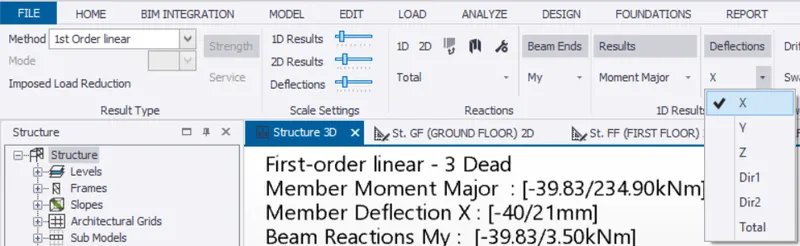
- After that select the direction, and to select the direction there will be an option named as the Deflection just click and then there will be a drop-down list and in that list there will be another options select the directions just as shown in the below given image:
- Below is the result for the diagram for the Bending moment as we can see the below image:
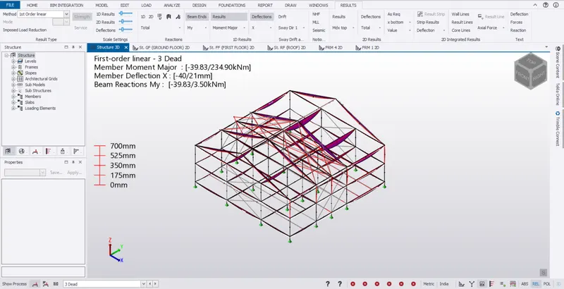
RESULT (Bending Moment Diagram):
Shear Force:
- Repeat the same procedure as we have done for the bending moment.
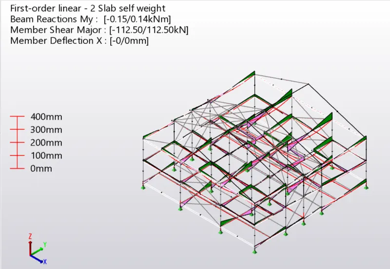
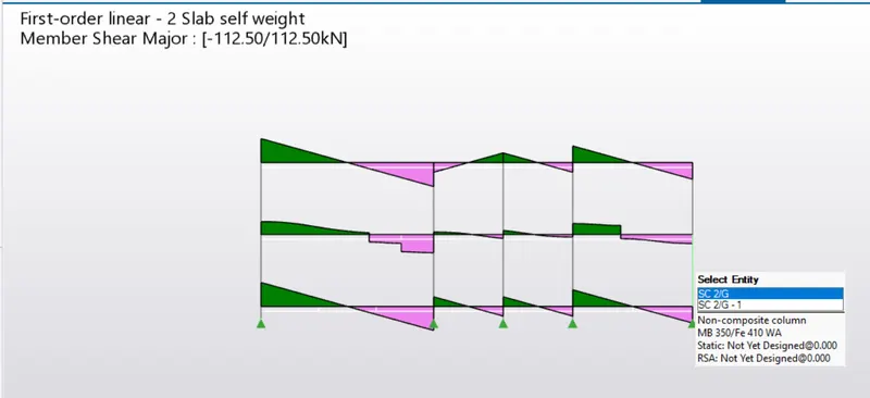
- Just go to the option Result in the Analyze tab click on that then there will be a drop-down list and in that list there will be an option called Shear Major (Fz) just click on that option just as shown in the below given image:
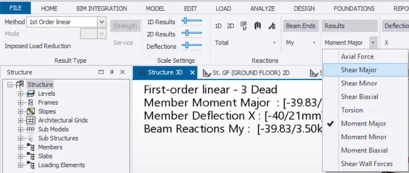
Result (Shear Major):
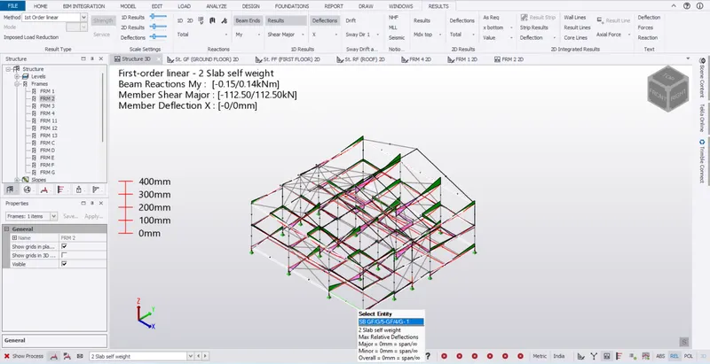
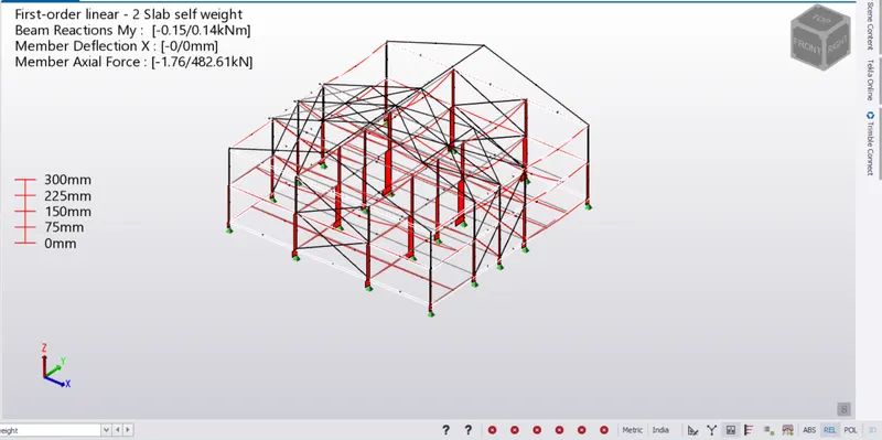
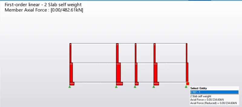
Axial Force:
2. Based on the analysis design the members and outline the thought process in selecting the member sizes along with the foundation design.
Solution:
AIM: To analyze the design the members and outline the thought process in selecting the member sizes along with the foundation design.
PROCEDURE:
- To analyze the design the members go to the Load tab just click on that option just as shown in the below given image:

- And in the Load tab there will be an option called Seismic Load just click on that option just as shown in the below given image:
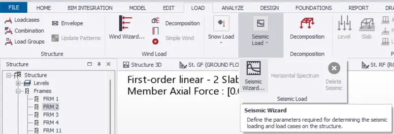
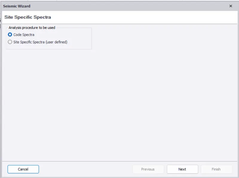
- After that there will be another dialouge box named as the Seismic Wizard (Site Specific Wizard) and click on the Code Spectra option and then click on the Next option just as shown in the below given image:
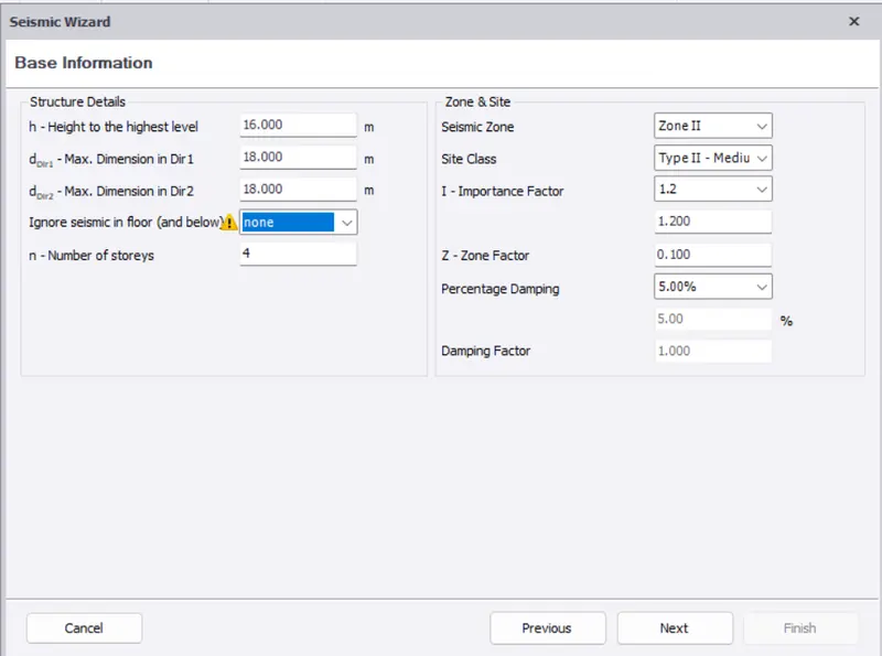
- Now after that there will be another dialouge box after clicking on the Next option named as the Base Information, fill the details just as shown in the below given image and then click on the option Next as shown below:
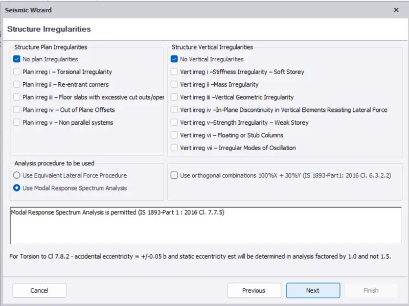
- Now after that there will be another dialouge box after clicking on the Next option named as the Structure Irregularities, fill the details just as shown in the below given image and then click on the option Next as shown below:
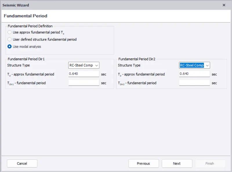
- Now after that there will be another diazlouge box after clicking on the Next option named as the Fundamental Period, fill the details just as shown in the below given image and then click on the option Next as shown below:
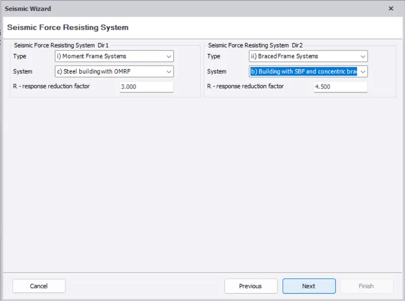
- Now after that there will be another diazlouge box after clicking on the Next option named as the Seismic Force Resisting System, fill the details just as shown in the below given image and then click on the option Next as shown below:
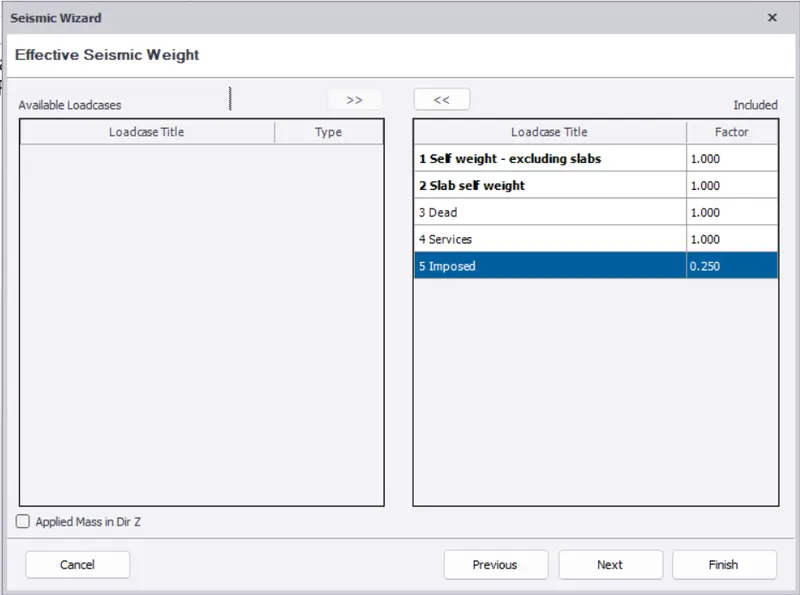
- Now after that there will be another diazlouge box after clicking on the Next option named as the Effective Seismic Weight and add the seismic weights, fill the details just as shown in the below given image and then click on the option Next as shown below:
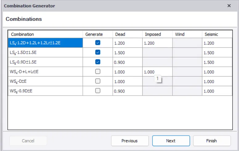
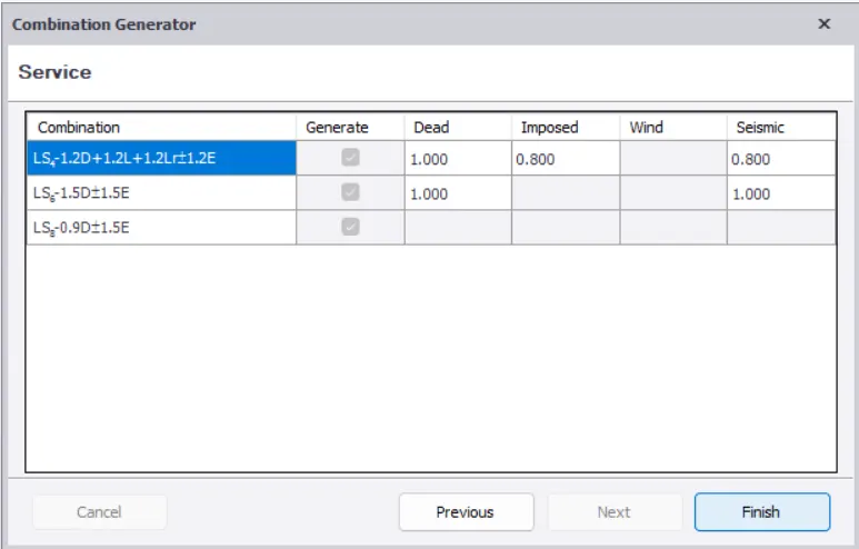
- Now after that there will be another diazlouge box after clicking on the Next option named as the Combination Generator(Combinations) and check the combination factor value as shown in the below given image:
- And to design the foundation under the columns go to the Foundation tab and in that tab there will be an option named as the Pad Base Column just as shown in the below given image:'

- Now go to the Base floor where we can create the foundations under the column.
- After going to the base floor go to the Column where we want to place the foundation just as shown in the below given image:
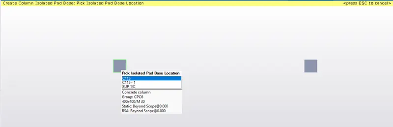
- Do the same procedure for all the columns just as shown in the below given image:
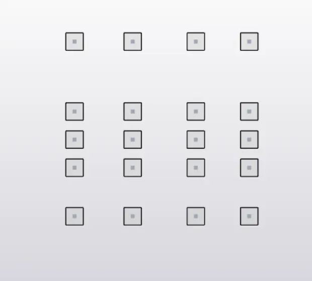
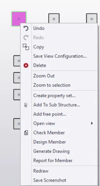
- Now we will be checking the members and to do so click right of the selected members and then there will be an option called Check Members just click on that option just as shown in the below given image:
- After that we can see there are some errors in the design so we will be redesign the foundation just as shown in the below given image:
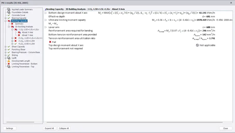
- After redesign the member we can see that there are no errors in the Bearing capacity but as we can see there is still some error as we can see in the below given image:
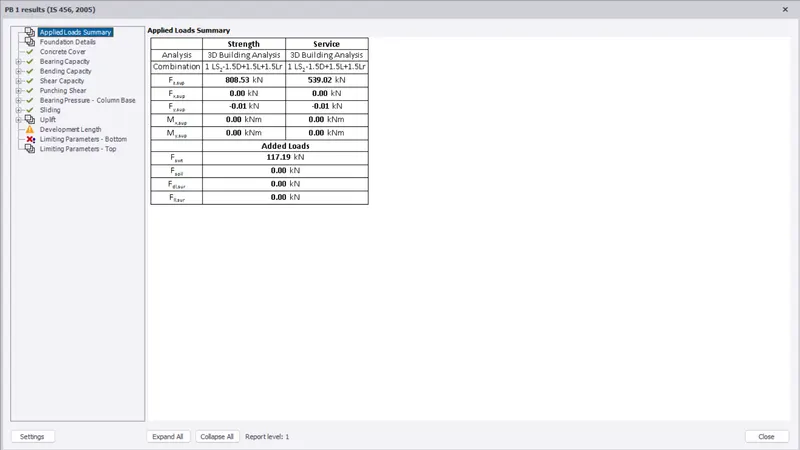
- Hence there are no errors in the foundation just as shown in the below given image:
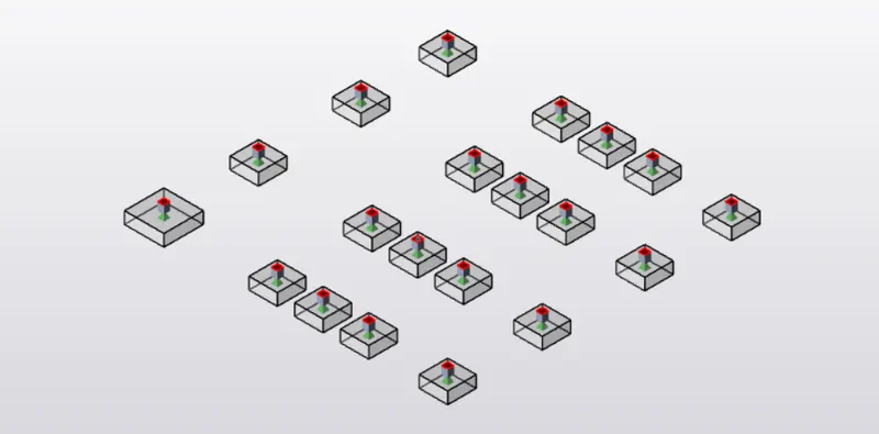
- Now we have successful designed the foundations below the column now we will be analyzing the structure.
- Now go to the analyze tab there will be an option called 1st Order Linear just click on that option just as shown in the below given image:
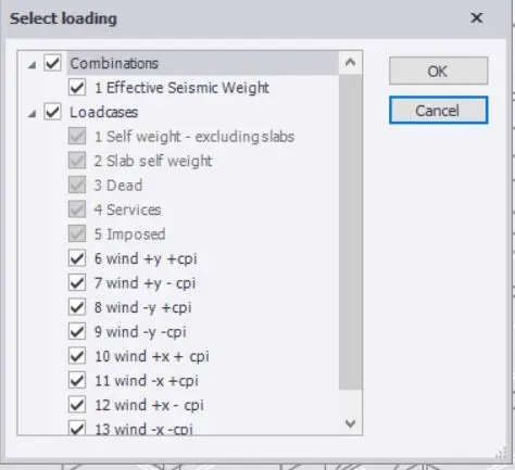
- After that,check all load cases and combination as shown in the below given image:
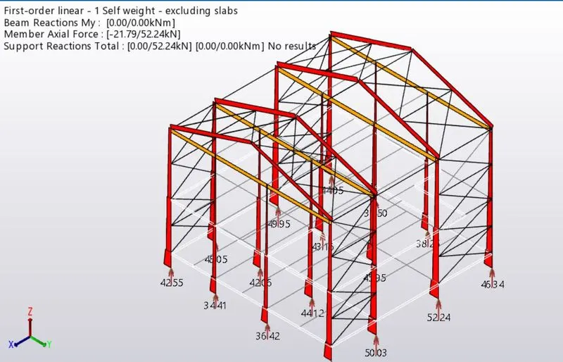
- Finally click ok, then to validate and analyze the structure to get all design Factors value just as shown in the below given image: