Thermodynamic analysis of tractor engine Preet 7549 model using GT Power
Aim:-> Thermodynamic analysis of tractor engine Preet 7549 model.
Introduction:
A tractor is an engineering vehicle specifically designed to deliver a high tractive effort (or torque) at slow speeds, for the purposes of hauling a trailer or machinery such as that used in agriculture, mining or construction. Most commonly, the term is used to describe a farm vehicle that provides the power and traction to mechanize agricultural tasks, especially (and originally) tillage, but nowadays a great variety of tasks. Agricultural implements may be towed behind or mounted on the tractor, and the tractor may also provide a source of power if the implement is mechanized.
PREET 7549 – 4WD Tractor is intended for carrying out the powerful general-purpose works in farming, main and preplant tillage, sowing, harvesting by use of high-performance combined and wide-cut aggregates, and transportation works. It is the base module to modify the tractors used in communal services and forestry. As the exception that confirms more wide capabilities of the conventional assembly tractors, the PREET 7549 – 4WD Tractor can be used on all types of work, including inter-row cultivation of tilled crops.

Problem setting:
Specification of Preet 7549 tractor model:
 |
From the above specification we get engine modelling parameters as-
- Bore = 105 mm
- Stroke = 118 mm
- Displacement = 4000 cc
- Type of engine = Diesel engine (CI engine)
- Number of cylinders = 4
- Turbocharged = Yes
- Cylinder geometry = Vertical inline
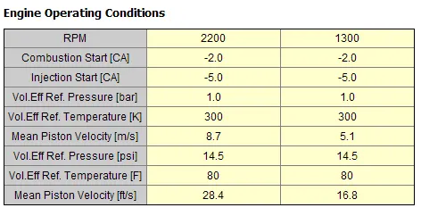
- Rated RPM = 2200
- Intermediate RPM = 1300
- HP generation = 75
As we know in GT power we have tutorial of multi-cylinder CI engine only for 6 cylinder. Hence only option is left to convert 6 cylinder engine to 4 cylinder engine.
Model of 6 cylinder CI engine:

To convert 6 cylinder engine into 4 cylinder engine we need to remove 2 cylinders. And then need to prepare model and change parameters as per 4 cylinder engine.
For example, the firing duration for 6 cylinder engine is 120 degrees then for 4 cylinder engine we need to change firing duration to 180 degrees.
EGR circuit model:

EGR works by recirculating a portion of an engine's exhaust gas back to the engine cylinder. This dilutes the O2 in the incoming air stream and provides gases inert to combustion to act as absorbents of combustion heat to reduce peak in-cylinder temperatures. NOx is produced in high temperature mixtures of atmospheric nitrogen and oxygen that occur in the combustion cylinder, and this usually occurs at cylinder peak pressure. Another primary benefit of external EGR valves on a spark ignition engine is an increase in efficiency, as charge dilution allows a larger throttle position and reduces associated pumping losses.
Cylinder geometry:


Firing order:

Inlet valve flow parameters:

Exhaust valve flow parameters:

The target performance values to achieve for model are as follows-
- Power: 75 HP
- BSFC: In range of 210 g/kW-h to 225 g/kW-h
- Rated A/F ratio: 25
- Intermediate A/F ratio: 22
Hence, power in KW can be computed as-
`"Power in KW"=0.7457xx"Power in HP" = 0.7457xx75`
`:."Power in KW"=55.9275`
`BSFC=(r)/(P)`
Where,
BSFC = Break specific fuel consumption in `(g/(KW.hr))`
P = Power in (KW)
r = Fuel consumption in `(g/(hr))`
`225=r/55.9275`
`:.r=55.9275xx225=12583.6875g/"hr"`
`:.r=12583.6875/3600=3.49546875g/(sec)`
To convert RPM to RPS,
`RPS=(RPM)/60=2200/60=36.66`
Hence, in 1 second 3.5 gram fuel is consume i.e., in 36.66 revolution 3.5 gram fuel is consuming.
Hence, for computing fuel consume per revolution-
`3.5/36.66=0.0954719g/(rev)=95.4719(mg)/(rev)`
For complete cycle = 190.9438 `(mg)/("cycle")`
The above obtaine fuel consumption is for 4 cylinder,
Hence for single cylinder, Fuel per cycle per cylinder = `190.9438/4=47.736mg`
Similarly compute fuel consumption for 1300 RPM, which is obtained as = 53.4 mg.
Injection parameters:

Case definition:

Post-processing:
~CASE A:
In this case only 4 cylinder engine is simulated, the engine is naturally aspirated without turbocharger.
Circuit diagram:

Results:


~CASE B:
In this case turbocharger is added to previous circuit to see effects on engine performance parameters.
Circuit diagram:

Result:


~CASE C:
In this case EGR is added to previous circuit to see effects on engine performance parameters.
Circuit diagram:

Result:


Observation and result comparison:
| Sr. no. | Parameter | Target values | Case A | Case B | Case C | ||||||
| Obtained value | Difference | Error % | Obtained value | Difference | Error % | Obtained value | Difference | Error % | |||
| 1 | Break power in HP | 75 | 65.1 | -9.9 | -13.2 | 72.1 | -2.9 | -3.8667 | 71.1 | -3.9 | -5.2 |
| 2 | BSFC in g/KW-hr | 225 | 261.1 | 36.1 | 16.0444 | 235.8 | 10.8 | 4.8 | 239.1 | 14.1 | 6.26667 |
| 3 | A/F ratio | 25 | 45.78 | 20.78 | 83.12 | 31.68 | 6.68 | 26.72 | 23.47 | -1.53 | -6.12 |
| 22 | 39.51 | 17.51 | 79.5909 | 21.67 | -0.33 | -1.5 | 19.15 | -2.85 | -12.955 | ||
Conclusion:-
Hence from above data it is seen that the targeted parameters are achieved with marginal errors and thus thermodynamic analysis is performed.