TETRA AND HEXA MESHING OF DIFFERENT COMPONENTS USING HYPERMESH.
1.Objective (tet mesh):
The main objective of this project is to create a 3D tetra mesh for the component (housing) as per the quality criteria given below.
Quality criteria:
Elements sizes: Min- 2mm, Target- 5mm, Max- 7mm
Tet collapse: 0.15
Procedure:
- Imported the file from the question and performed the 2d tria shell elements to 3d tetra elements method.
- So first, checked for the solid component and deleted it.
- defeatured the surface fillets within the range of 0.5 to 8mm.
- Checked for the surface free edges and performed the topology cleanup.
- Eliminated the surfaces which fail for the minimum length using the quick edit panel.
- Generated 2d tria shell elements of size 5mm and checked for the elements which fail for minimum and a maximum length of 2 and 7mm respectively.
- By assigning the tetra mesh parameters, converted the 2d shell elements to 3d tetra elements.
- Checked for the elements which fail for tet collapse of 0.15mm.
- Corrected the elements which fail for tet collapse using the distance option key F4.
- Finally, eliminated the elements which fail for tet collapse using the options like a mask, tetra remesh, distance, etc.
- Saved the file.
Note: I performed the above-mentioned procedure for the following components.
images of the model:
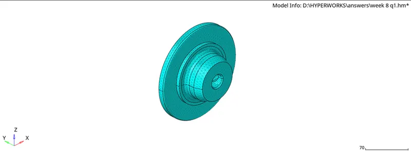
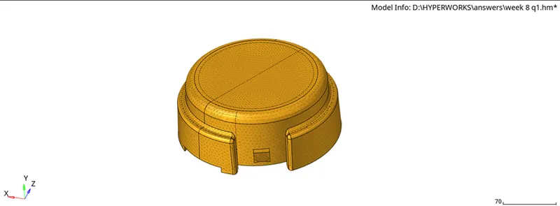
Link to view the model:
result:
Hence, the 3D tetra mesh for the component (housing) is created as per the quality criteria.
2.Objective (tet mesh):
The main objective of this project is to create a 3D tetra mesh for the components as per the quality criteria given below.
Quality criteria:
Elements sizes: Min- 2mm, Target- 6mm, Max- 7mm
Tet collapse: 0.15
Procedure:
- Imported the file from the question and performed the 2d tria shell elements to 3d tetra elements method.
- so first, checked for the solid component and deleted it.
- defeatured the surface fillets within the range of 0.5 to 8mm.
- checked for the surface free edges and performed the topology cleanup.
- eliminated the surfaces which fail for the minimum length using the quick edit panel.
- generated 2d tria shell elements of size 6mm and checked for the elements which fail for minimum and a maximum length of 2 and 7mm respectively.
- by assigning the tetra mesh parameters, converted the 2d shell elements to 3d tetra elements.
- checked for the elements which fail for tet collapse of 0.15mm.
- corrected the elements which fail for tet collapse using the distance option key F4.
- finally, eliminated the elements which fail for tet collapse using the options like mask, tetra remesh, distance, etc...
Note: I performed the above-mentioned procedure for the following components.
images of the model:
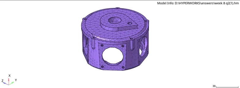
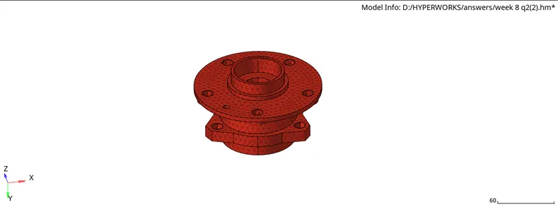
procedure:
- performed volume tetra method.
- assigned the tetramesh parameters such as minimum length of 2mm, the maximum length of 7mm, and tet collapse of 0.15mm.
- generated 3D tetra elements of size 6mm using the volume tetra option.
- checked for the elements which fail for tet collapse of 0.15mm.
- corrected the elements which fail for tet collapse using the distance option key F4.
- eliminated the elements which fail for tet collapse using the options like mask, tetra remesh, distance, etc...
- Finally, saved the file.
Note: I performed the above-mentioned procedure for the following components.
images of the model:
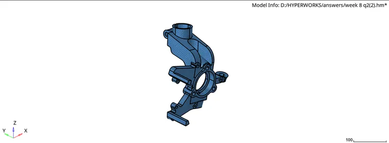
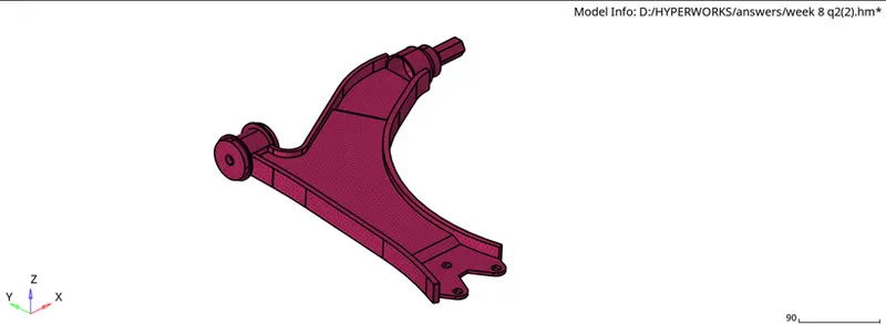
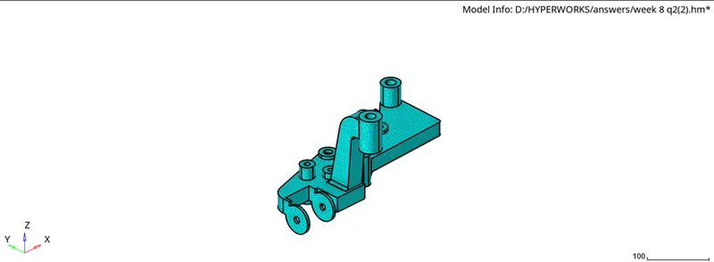
Image of the whole model:
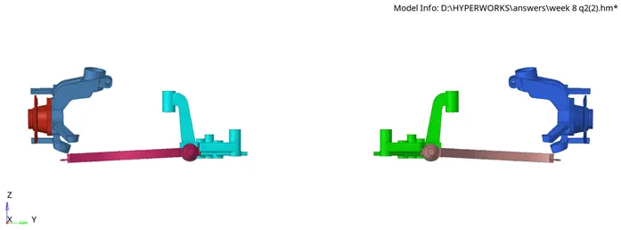
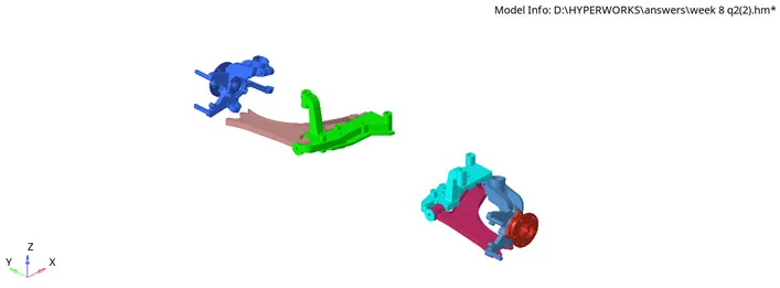
Link to view the model:
result:
Hence, the 3D tetra mesh for the components is created as per the quality criteria given.
3.objective (hex mesh):
The main objective of this project is to create a 3D hex mesh for the component (arm bracket).
procedure:
- imported the .hm file in the hypermesh GUI.
- checked for any topological failures in the model.
- checked for any geometrical irregularities, surface duplicates.
- checked for the presence of a solid component.
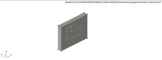
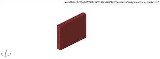
- component 1- base:
- created 2d shell mesh of size 10mm on the top surface of the component.
- used 3d-->line drag-->drag elements with the on drag of 5 layers to create the solid mesh.

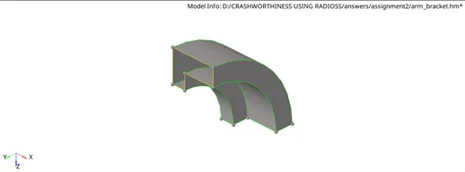
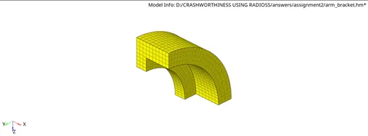
- component 2- arm curve:
- using the 2d shell elements on the base to spin created the solid mesh elements.
- used 3d-->spin-->spin elements.

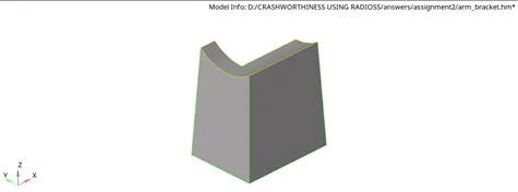
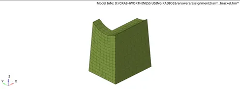
- component 3-arm straight:
- used tools-->faces option to get the shell elements from arm curve.
- meshed the other end of the arm straight with size 10mm.
- used the 3d-->linear solid option to create the solid mesh.
- deleted the faces.

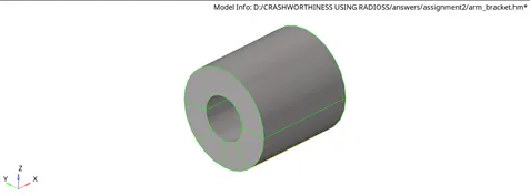
- component 4-boss:
- created 2d shell elements on one surface of the boss.
- since the arm straight connects the boss, meshed the surface with even to the arm straight connecting portion.
- used 3d-->solid map-->general to create the solid mesh.
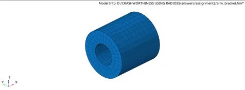

- after creating the solid mesh, checked for the presence of shell elements, and deleted.
- checked for any free edges between the elements.
- finally, saved the model.
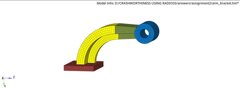
Link to view the model:
result:
Hence, the 3D hex mesh for the component (arm bracket) is created.