Switch Bezel Design
Aim:
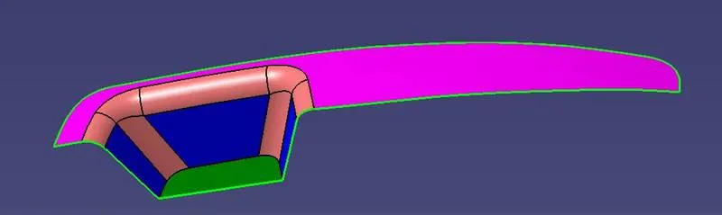
To create a solid from the drawings given and perform Draft Analysis.
Procedure:
- Open the Generative Shape Design from the Start Menu in software.
- Select the open option from the File menu.
- Select the model and click on Open.
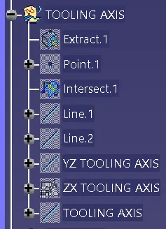
Tooling Axis:
- Intersect the model with the plane perpendicular or to an axis system.
- Extend the lines which are perpendicular to the plane.
- Again intersect the model with another plane and extend the lines perpendicular to it.
- Create a bisecting line by bisecting option in Line definition.
- Rename it as Tooling Axis.
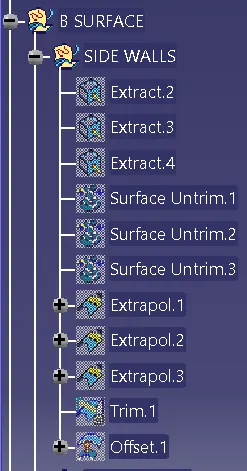
Class B Surface:
Side Walls:
- Extract the side walls with no propagation in extract option.
- Untrim them.
- Extrapolate the walls with point continuity of distance 20mm.
- Trim the walls to get the required shape.
- Offset those trimmed walls with thickness value.
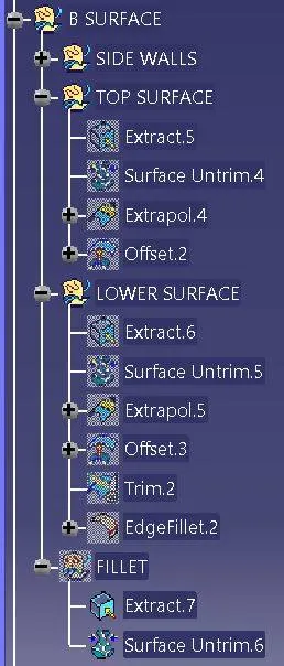
Top & Bottom Surfaces:
- Extract the surfaces separately and untrim them.
- Extrapolate the surfaces with required distances.
- Offset them with thickness value.
- Trim them for required shape.
- Measure the fillets, calculate it and create fillets.
Class C Surface:
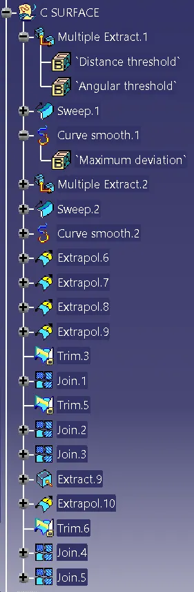
- Get the boundary lines of Class A surface separately.
- Smooth the curves with a smooth option as boundary lines have a lot of vertices.
- Sweep the curves with tooling axis as direction in Sweep option.
- As both lines do not intersect, extrapolate them with a certain distance.
- Trim the surfaces.
Final model:
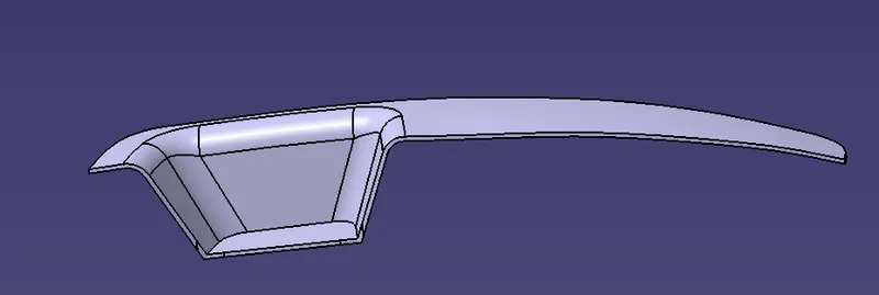
- Join the Class A and Class C surfaces.
- Trim those joined surfaces with Class B surfaces.
- Go to Part Design and insert a Body.
- Create a closed surface.
Draft Analysis:
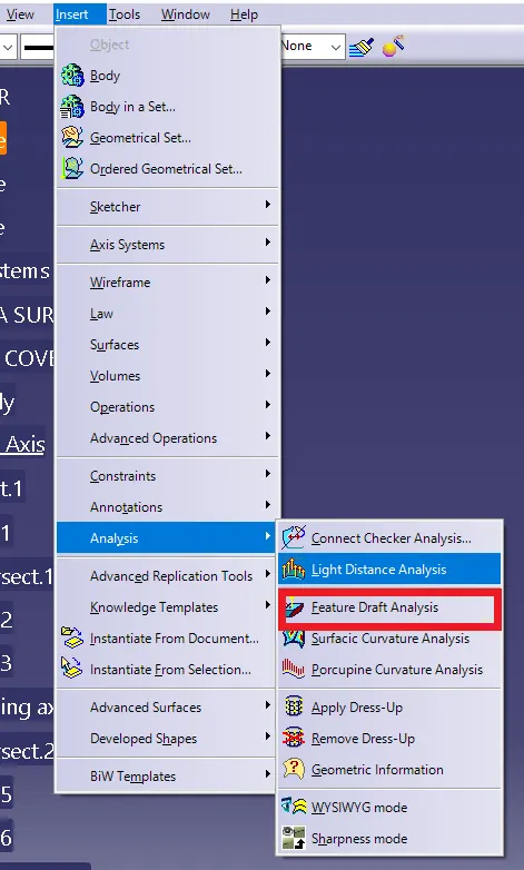
- Go to the Insert menu and select the Analysis option.
- Select Feature Draft Analysis.
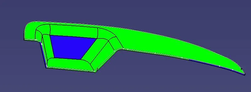
- Select the Material option and select the surface.
- Drag the compass and place on tooling axis.
- Make sure that the top surface is in green colour as draft angle should not exceed 3deg.
- Click on Okay after confirm the model.
Result:
A solid is created from the given drawings and performed the Draft Analysis.