Switch Bezel Design Using CATIA
Aim:
The main aim is to complete the given Class A model into a surface with a thickness of 2.5 mm.
Procedure:
- Checking the Class A Surface Tooling Axis:
- Initially, the model is opened using the Open Command. Once, the model is opened, we check the given Class-A surface of the given Switch Bezel.
- We rotate the model to see at which plane the whole surface can be seen completely.
- Here we can see the whole model on Z-axis.
- Creating the Tooling Axis:
- Since we already know that the whole Surface is seen at Z-Axis, the direction of the tooling axis is in the Z-axis.
- Now, the direction is known but the position is unknown. Therefore, the Base is selected.
- Once the base is selected, the Extract option is used. (Extract option can be found in Operation Toolbox in the Generative Shape Design)
- A point is selected on the extracted base and the point dimensions are given as ‘0’ such that the point falls on the center.
- To create a line in the X Direction, we use the Intersection option to Create the line on the Class A surface.
- Once the intersection line is created, the small angled parts (Drafted lines) are selected and the Lines are drawn on them.
- To Create an Axis line on the ZX plane. The Lines drawn are bisected with a point creating a Tooling axis in the ZX direction.
- Now to create the axis in the ZY direction follow the similar steps (as mentioned above) to attain the Tooling axis in the ZY direction.
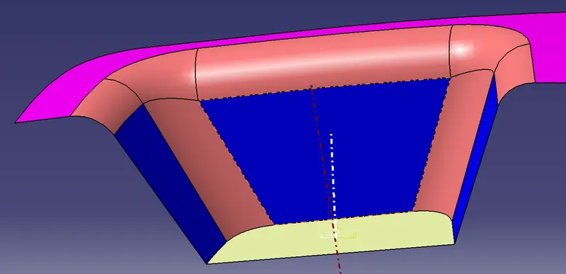
- Once both the axes are created, the two axes are bisected to get the Tooling Axis.
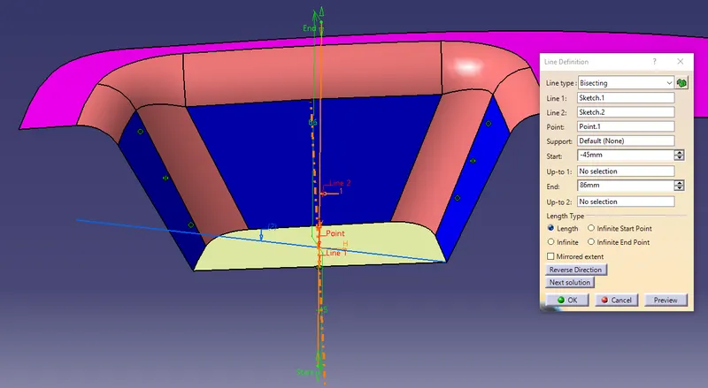
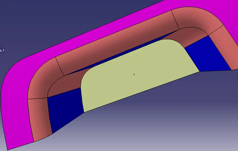
- Checking for Draft Analysis:
- Once the Tooling axis is created, the Draft analysis is done on the surface.
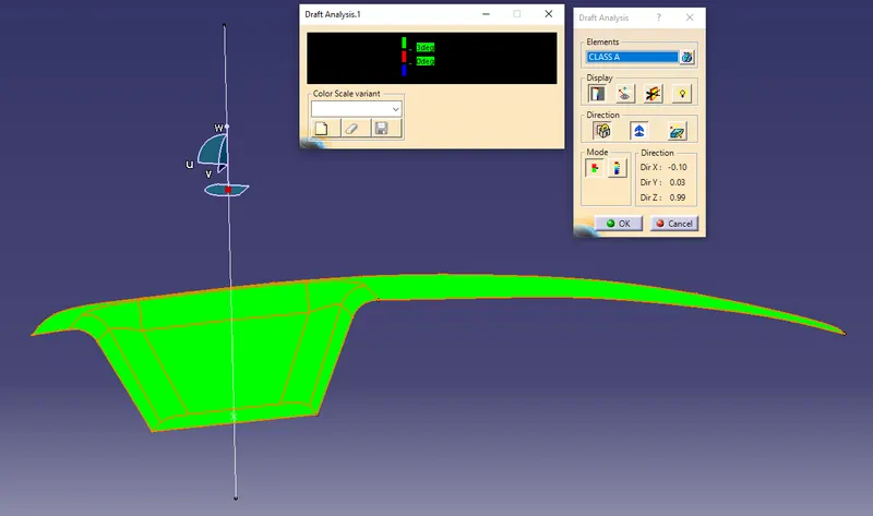
- To perform Draft Analysis, Go to the insert Menu >> Click Analysis >> Click Feature Draft Analysis option >> New Dialog boxes opens.
- Select the Elements as the Class A Model and the Direction as the Tooling Axis using the Compass option to define a new direction of the draft.
- Click OK to check if all the surface comes under the within the limits of 0 to 3 degrees.
- If the draft is more than 3 Degree then the surface will be shown as green.
- Creating the B-surface:
- To create a B surface, we need to offset the Class A Surface but the Surface cannot be the same as the Class A as it would create errors while the model is sent for prototyping.
- We start with extracting the Top surface and Offset it to the thickness of the model (that is 2.5mm). Now, extract the groove parts and the base part and offset it to the same thickness.
- Now un-trim the extracted surfaces and extrapolate the surfaces such that every surface intersects with the neighboring surfaces. After completing the extrapolating, trim the surface such that the extracted surface is similar to that of the class A-surface (without fillets).
- The surface then needs to be filleted as the Class A surface with the 2.5mm added or removed by fillet radius.
- Creating the C surface:
- After creating the B surface, the C surface needs to be created. To create the C surface, the sweep option is used.
- To create a sweep, there should be a boundary created to it. The boundary should be created separately as creating the boundary completely doesn’t create the sweep smoothly as the model contains the main unnecessary lines.
- To cover those, the smooth option is used to create the smooth surface and the Class A surface model is swept smoothly over the plane areas. Over the draft angled areas, the boundary should be created separately to create the sweep over that area.
- Now join the Class C surfaces together to create the surface.
- Joining the Surfaces:
- Now, start with joining the Class A and Class C surfaces together.
- Next, trim the combined surface with the Class B Surface to create the final surface.
- Creating the Solid:
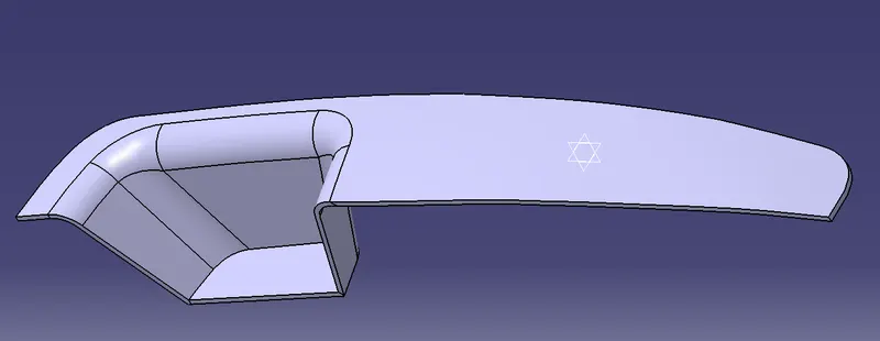
- After creating the surface, go to the Part design option and create the solid using the closed surface option.
- The solid is created.
Results:
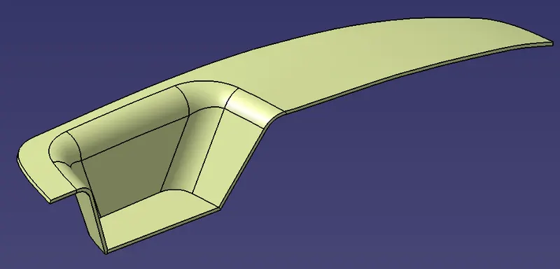
The switch Bezel component is created from the Class A surface and performed the Draft Analysis.
Tree Structure:

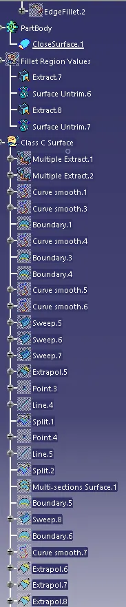
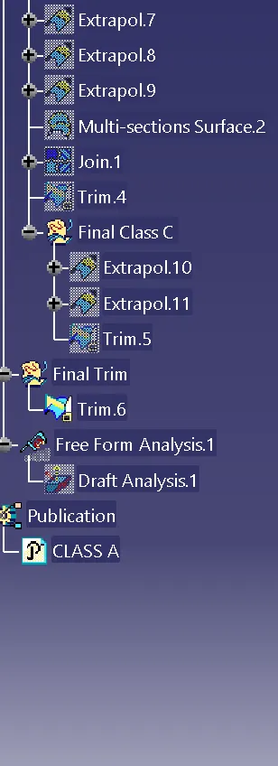
Surface CAD:
Solid CAD:
Learning Outcomes:
- Learned how to create the Class B and Class C surface
- Learned how to create the Draft Analysis.