Study of Transfer Function.
Aim: To study transfer function.
Objectives:
01.
To study autonomous driving systems in hybrid electric cars.
02.
To study application of transfer function and state space in matlab.
03.
To learn derivation of transfer function for electric circuits.
Introduction:
What is Transfer Function?
A transfer function represents the relationship between the output signal of a control system and the input signal, for all possible input values.
What is State Space?
A state space is the set of all possible configurations of a system. It is a useful abstraction for reasoning about the behavior of a given system and is widely used in the fields of artificial intelligence and game theory.
Problem Statement:
01.
How hybrid electric cars can be operated more efficiently by autonomous driving systems?
02.
A. By using the below transfer function solve the different questions:
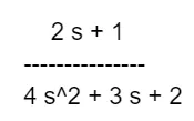
i) Define the above transfer function in the MATLAB Command Window.
ii) Convert the same in the State-space by using a relevant MATLAB command.
iii) Store the converted data under a diffferent variable named 'H'.
B. By using the relevant command, convert the State-space to transfer function.
03.
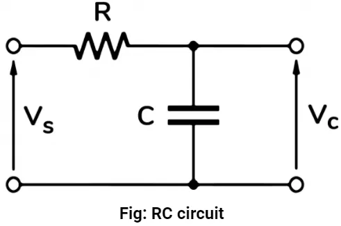
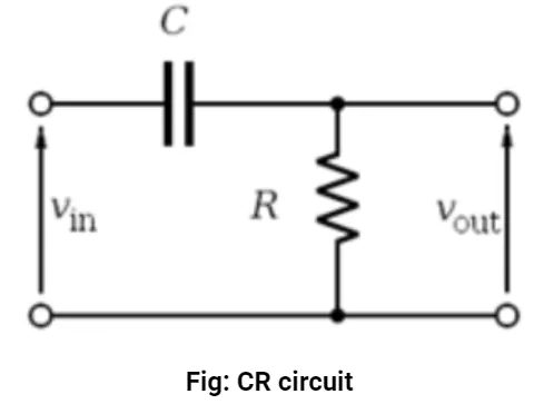
Derive the transfer functions for the RC(output across C) and CR (output across R) circuits shown below. Are they equal?
Note: RC circuit: Vs= Input voltage, Vc= output voltage.
CR circuit: Vin=Input voltage, Vout= output voltage.
Solution:
01.
How hybrid electric cars can be operated more efficiently by autonomous driving systems?
Global Positioning System (GPS):
The GPS system works by communicating with global satellites that respond back with the coordinates of its current location. It uses information from satellite map to inform about the current spot of the vehicle. Individual owners will be certainly benefited by having it installed in their vehicle as it helps them to effectively monitor their vehicle. Installing the tracker will take just minutes. Having it will give immense security because you know that the vehicle’s location can be monitored at any time. If a vehicle is stolen, the system can be used to track its location right away. Some GPS tracking solutions come with advanced features such as automatic alert to the nearest policy station in the event of an accident or built-in access to emergency help. Rental car companies will particularly benefit through it because passengers will feel confident that the vehicle in which they are travelling is being monitored. It increase operational efficiency and safety, assists in rescue in case of an emergency and provides data for logistics.
Light Detection and Ranging (LiDAR):
You might have noticed a rotating device installed atop an autonomous vehicle. However, on some, it’s mounted on the bonnet. This device is LiDAR that acts as an eye of the self-driving vehicles. It provides them a 360-degree view of the surrounding helping them to drive themselves safely.
Continuously rotating LiDAR system sends thousands of laser pulses every second. These pulses collide with the surrounding objects and reflect back. The resulting light reflections are then used to create a 3D point cloud. An onboard computer records each laser’s reflection point and translates this rapidly updating point cloud into an animated 3D representation.
3D representation is created by measuring the speed of light and the distance covered by it which helps to determine the vehicle’s position with other surrounding objects.
The 3D representation monitors the distance between the other passing by vehicle and any other vehicle in front of it. It helps to command the brakes to slow or stop the vehicle. When the road ahead is clear, it also allows the vehicle to speed up.
Video Cameras:
Safety First
Safety should always be your number one priority. With a transportation fleet, it can be difficult to know what’s going on at all times. Your only hope is to invest in fleet driving cameras, which will allow for greater surveillance of any suspicious or dangerous behavior. While you want to trust your drivers and staff, you can never be too careful. Fleet camera systems will help you crack down on bad driving behaviors and other safety issues, before a small problem turns into a big one! They also help with any public safety concerns on transportation systems across the country. This is a major tool for fleets throughout the U.S. that can keep safe by constantly monitoring the vehicles.
Protection
Protecting your company is another priority. Fleet camera systems make it possible to capture any unfortunate incident on tape. This includes anything from theft and robbery to fighting and bullying. With surveillance video, you can identify any safety or security concerns and find stronger, quicker solutions. Fleet cameras also provide a sense of backup for any company worried about potential lawsuits or legal battles. Surveillance video can prove a company was not responsible for an accident, sparing businesses millions in legal fees, lawsuits and settlements. With a camera on your dashcam recording the interior of the vehicle, you can show that a driver was not distracted by a cell phone or that they were wearing their seatbelt. It’s so important to take precautions to ensure the safety and protection of your fleet.
Radar Sensors:
Radar is widely used because it has some unique strengths. Radar can reliably indicate how far away an object is. Typical long-range automotive radars can provide range measurements on objects that are as much as 300 meters to 500 meters away. Because radar uses radio waves instead of light to detect objects, it works well in rain, fog, snow and smoke. This stands in contrast to optical technologies such as cameras – or in the future, lidar – which are generally susceptible to the same challenges as the human eye. Consider the last time you were blinded by direct sunlight while driving, or tried to see clearly through a windshield covered with dirt and grime. Optical sensors have the same challenges, but radars can still see well in those cases. And unlike cameras, radar does not need a high-contrast scene or illumination to sense well at night.
At the same time, radar makes inherent measurements of relative speed, so at the same time it is providing a range measurement, it can also tell how quickly something is moving toward the vehicle or away from it. Cameras and lidars may need to take multiple images over time to estimate relative speed. Radar, by contrast, can be placed behind vehicle grilles, in bumpers, or otherwise hidden away, giving designers significant flexibility to focus on vehicle aesthetics.
Ultrasonic Sensors:
Ultrasonic sensors mimic echolocation used by bats, transmitting high-frequency sound waves to gauge the distance between objects within close range.
Ultrasonic sensors can be used to complement other vehicle sensors, including radar, cameras, and lidar, to get a full picture of the immediate surroundings of a vehicle. While ultrasonic sensors necessitate close proximity and slow speeds, advantages include the ability to be accurately used in situations with low visibility, such as in inclement weather conditions and dim areas.
Central Computer:
All cars manufactured today contain at least one computer. It is in charge of monitoring engine emissions and adjusting the engine to keep emissions as low as possible. The computer receives information from a many different sensors, including:
- The oxygen sensor
- The air pressure sensor
- The air temperature sensor
- The engine temperature sensor
- The throttle position sensor
- The knock sensor
- The oxygen sensor
Using the information from these sensors, the computer can control things like the fuel injectors, spark plugs and the idle speed to get the best performance possible from the engine while keeping emissions low. The computer can also sense when something has gone wrong and can inform the driver with the "Check Engine" light. A mechanic can read a diagnostic code from the computer and fix the problem.
02.
A. By using the below transfer function solve the different questions:
i) Define the above transfer function in the MATLAB Command Window.
ii) Convert the same in the State-space by using a relevant MATLAB command.
iii) Store the converted data under a diffferent variable named 'H'.
B. By using the relevant command, convert the State-space to transfer function.
clear all
close all
clc

% Method-01
% Defining numerator and denumerator of the transfer function.
num = [2 1];
den = [4 3 2];

% Defining transfer function using 'tf' under variable 'T'.
T = tf(num,den)

% Converting Transfer function into State space using 'tf2ss'
[A,B,C,D] = tf2ss([num],[den])

% Method-02
% Assigning numerator and denumerator of the transfer function directly
% using 'tf' under variable 'Z'.
Z = tf([2,1],[4,3,2])

% Converting Transfer function into State space using 'tf2ss'
[A,B,C,D] = tf2ss([2,1],[4,3,2])

% Converting Stste space into Transfer function and storing the converted data under variable 'H'.
A = [-0.75 -0.50; 1.00 0];
B = [1; 0];
C = [0.50 0.25];
D = [0];

[num,den] = ss2tf(A,B,C,D,1);

H = tf(num,den)
Scriptfile for matlab program of transfer function.
Results for program:

Method-01: Transfer function under variable 'T'.

Method-02: Transfer function under variable 'Z'.

State space matrix: A

State space matrix: B

State space matrix: C

State space matrix: D

Converted transfer function under variable 'H'.
Link for matlab scriptfile_Transfer function.
03.
Derive the transfer functions for the RC(output across C) and CR (output across R) circuits shown below. Are they equal?
Note: RC circuit: Vs= Input voltage, Vc= output voltage.
CR circuit: Vin=Input voltage, Vout= output voltage.
Fig01: RC circuit.
For RC circuit:
Vs = Input voltage.
Vc = Output voltage.
Vs(t) = Input voltage in time domain.
Vo(t) = Output voltage in time domain.
Vs(s) = Input voltage in s domain.
Vo(s) = Output voltage in s domain.
i(t) = Current in time domain.
I(s) = Current in s domain.
R = Resistance of resistor.
C = Capacitance of capacitor.
t = Time.
s = Complex variable.
Current is flowing in counter clockwise direction.
By appyling kirchhoff's voltage law.
`Vs(t)=Ri(t)+1/Cinti(t)delt`
... equation [01]
`Vc(t)=1/Cinti(t)delt`
... equation [02]
Converting equations 1 and 2 in s-domain.
`Vs(s)=RI(s)+1/CI(s)`
... equation [03]
`Vc(s)=1/CI(s)`
... equation [04]
`I(s)=Vc(s)*I`
... equation [05]
Substituting equation 05 in equation 03.
`Vs(s)=RVc(s)*C+Vc(s)`
`Vs(s)=Vc(s)[RC+1]`
`frac(Vc(s))(Vs(s))=frac(1)(1+RC)`
... equation [A]
Fig02: CR circuit.
For CR circuit:
Vi = Input voltage.
Vo = Output voltage.
Vi(t) = Input voltage in time domain.
Vo(t) = Output voltage in time domain.
Vi(s) = Input voltage in s domain.
Vo(s) = Output voltage in s domain.
i(t) = Current in time domain.
I(s) = Current in s domain.
R = Resistance of resistor.
C = Capacitance of capacitor.
t = Time.
s = Complex variable.
Current is flowing in counter clockwise direction.
By appyling kirchhoff's voltage law.
`Vi(t)=Ri(t)+1/Cinti(t)delt`
... equation [01]
`Vo(t)=Ri(t)`
... equation [02]
Converting equations 1 and 2 in s-domain.
`Vi(s)=RI(s)+1/CI(s)`
... equation [03]
`Vo(s)=RI(s)`
... equation [04]
`I(s)=frac(Vo(s))(Ri)`
... equation [05]
Substituting equation 05 in equation 03.
`Vi(s)=Vo(s)+1/C*frac(Vo(s))(R)`
`Vi(s)=Vo(s)*[frac(1+RC)(RC)]`
`frac(Vo(s))(Vi(s))=frac(RC)(1+RC)`
... equation [B]
From equation [A] and equation [B] we can conclude that transfer functions for RC circuit across capacitor and CR circuit across resistor are not same.
Conclusion:
We studied defination of the transfer function and it's application in RC and CR circuits.
We studied the conversion of transfer function into state space and vice-versa.