Study of 6 kW 45 Vdc Fuel Cell Stack in matlab.
Aim: To study the 6 kW 45 Vdc Fuel Cell Stack in matlab.
Objectives:
01.
To study the working priniciple of the model in detail.
02.
To study simulation of the model and the results.
03.
To study the voltage and current characteristics in resultant graph.
Introduction:
What is Fuel Cell?
A fuel cell is an electrochemical cell that converts the chemical energy of a fuel (often hydrogen) and an oxidizing agent (often oxygen) into electricity through a pair of redox reactions. Fuel cells are different from most batteries in requiring a continuous source of fuel and oxygen (usually from air) to sustain the chemical reaction, whereas in a battery the chemical energy usually comes from metals and their ions or oxides that are commonly already present in the battery, except in flow batteries. Fuel cells can produce electricity continuously for as long as fuel and oxygen are supplied.
A fuel cell is a device that generates electricity through an electrochemical reaction, not combustion. In a fuel cell, hydrogen and oxygen are combined to generate electricity, heat, and water. Fuel cells are used today in a range of applications, from providing power to homes and businesses, keeping critical facilities like hospitals, grocery stores, and data centers up and running, and moving a variety of vehicles including cars, buses, trucks, forklifts, trains, and more.
Fuel cell systems are a clean, efficient, reliable, and quiet source of power. Fuel cells do not need to be periodically recharged like batteries, but instead continue to produce electricity as long as a fuel source is provided.
A fuel cell is composed of an anode, cathode, and an electrolyte membrane. A typical fuel cell works by passing hydrogen through the anode of a fuel cell and oxygen through the cathode. At the anode site, a catalyst splits the hydrogen molecules into electrons and protons. The protons pass through the porous electrolyte membrane, while the electrons are forced through a circuit, generating an electric current and excess heat. At the cathode, the protons, electrons, and oxygen combine to produce water molecules. As there are no moving parts, fuel cells operate silently and with extremely high reliability.
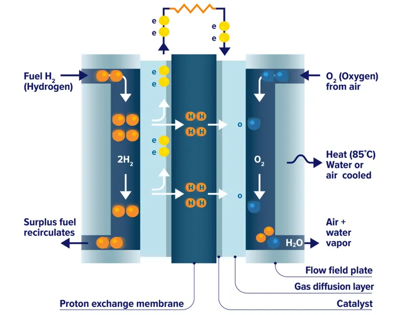
Fig01: Internal construction of fuel cell.Due to their chemistry, fuel cells are very clean. Fuel cells that use pure hydrogen fuel are completely carbon-free, with their only byproducts being electricity, heat, and water. Some types of fuel cell systems are capable of using hydrocarbon fuels like natural gas, biogas, methanol, and others. Because fuel cells generate electricity through chemistry rather than combustion, they can achieve much higher efficiencies than traditional energy production methods such as steam turbines and internal combustion engines. To push the efficiency even higher, a fuel cell can be coupled with a combined heat and power system that uses the cell’s waste heat for heating or cooling applications.
Fuel cells are also scalable. This means that individual fuel cells can be joined with one another to form stacks. In turn, these stacks can be combined into larger systems. Fuel cell systems vary greatly in size and power, from combustion engine replacements for electric vehicles to large-scale, multi-megawatt installations providing electricity directly to the utility grid.
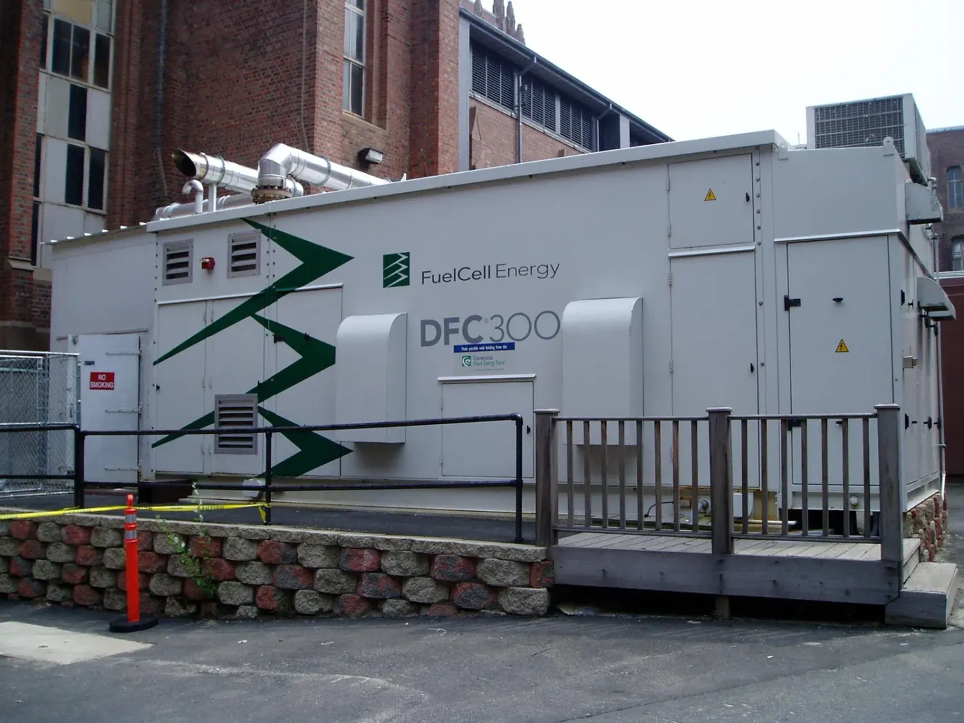
Fig02: Molten carbonate (stacked) fuel cell.
Proton Exchange Membrane Fuel Cell:Proton Exchange Membrane Fuel Cells (PEMFCs) use a polymer membrane for its electrolyte and a precious metal, typically platinum, for its catalyst. What distinguishes these fuel cells from others is PEMFC’s ability to operate at cooler temperatures relative to other types of fuel cells, between 80 to 200 degrees Fahrenheit. Pure hydrogen gas is the typical fuel for PEMFCs Due to their use of precious metals and lower operating temperatures.
PEMFCs operate between 40% to 60% efficiency and are capable of handling large and sudden shifts in power output. PEMFCs are well-suited for cars and other specialty vehicles such as forklifts that need to quickly start up or accelerate. Additionally, PEMFC’s can be scaled in stationary applications for use in telecommunications, data centers, and residential markets.
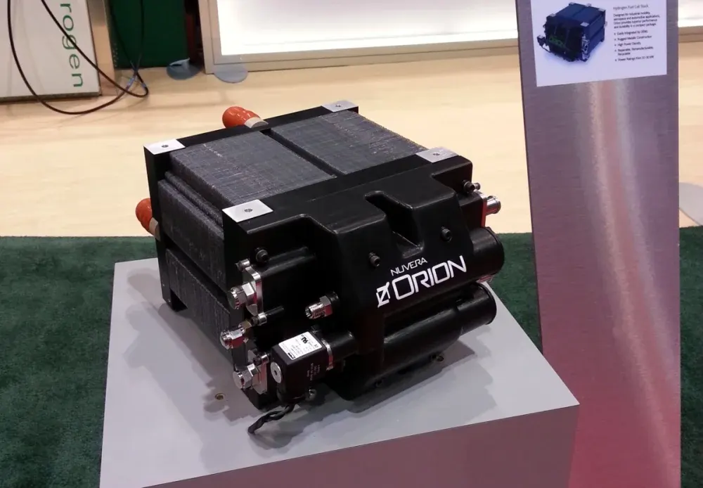
Fig03: Proton Exchange Membrane Fuel Cell.
Benefits:
-
Low-to-Zero Emissions -
High Efficiency -
Reliability -
Fuel Flexibility -
Energy Security -
Durability -
Scalability -
Quiet Operation
Problem statement:
01.
Explain the working priniciple of the model in detail.
02.
Simulate the model and explain the results.
03.
Explain the voltage and current characteristics in your resultant graph.
Solution:
01.
Explain the working priniciple of the model in detail.
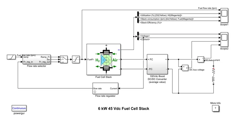
Fig04: Matlab model-6KW 45Vdc Fuel Cell stack.
This example shows the Proton Exchange Membrane (PEM) Fuel Cell Stack model feeding an average value 100Vdc DC/DC converter where a resistor–inductor circuit (RL circuit) is used to define the load in order to test the behaviour of the fuel cell under predifined conditions.
Model consists of ramp block, flow rate selector block, switch block, saturation block, flow rate regulator block, fuel cell stack block, DC/DC converter block and scope.
First we will discuss the function of each block one by one.
Ramp block: It is used to genetrate continuously increasing or decreasing signal after a specified time lapse, thus we need to enter the parameters accordingly.
Flow rate selector block: It is used to select the rate of flow (50 lpm or 80 lpm) and it is done by comparing ramp signal and flow regulator signal and selecting one of them by using a switch block.
Switch block: It is used to select any one of the assigned signal.
Saturation block: It only allows signals within specified tolerances and all the other signals are chopped like a chopper i. e. limiting the input signal within lower and upper saturation values.
Flow rate regulator: It moniters and controls the rate of flow of fluid, for that we have to enter the values of characteristics of the fluid. It working is defined by the current (current delivered by the fuel cell stack) as a input signal.
Fuel cell stack: It is a fuel cell stack block which performs as a fuel cell stack to generate the energy.
DC/DC converter: It simply converts the supplied DC signals into required DC signals in order to match the requirements of the load with the generation of the fuel cell.
Working principle:
The model 6KW 45Vdc fuel cell stack block operates on the principle of conversion of energy from one form to another. Here the fuel cell converts the chemical energy of the of a fuel (often hydrogen) and an oxidizing agent (often oxygen) into electric energy through a pair of redox reactions.
Fuel cells requires a continuous source of fuel and oxygen (usually from air) to sustain the chemical reaction. Fuel cells can produce electricity continuously for as long as fuel and oxygen are supplied.
Working:
The nominal Fuel Cell Stack voltage is 45Vdc and the nominal power is 6kW. The converter is loaded by an RL element of 6kW with a time constant of 1 sec. During the first 10 secs, the utilization of the hydrogen is constant to the nominal value (Uf_H2 = 99.56%) using a fuel flow rate regulator. After 10 secs, the flow rate regulator is bypassed and the rate of fuel is increased to the maximum value of 85 lpm in order to observe the variation in the stack voltage. That will affect the stack efficiency, the fuel consumption and the air consumption.
Fuel cell voltage, current, DC/DC converter voltage and DC/DC converter current signals are available on the Scope-2. Fuel flow rate, Hydrogen and oxygen utilization, fuel and air consumption, and efficiency are available on the Scope-1.
Simulation:
At t = 0 s, the DC/DC converter applies 100Vdc to the RL load (the initial current of the load is 0A). The fuel utilization is set to the nominal value of 99.56%. The current increases to the value of 133A. The flow rate is automatically set in order to maintain the nominal fuel utilization. Observe the DC bus voltage (Scope2) which is very well regulated by the converter. The peak voltage of 122Vdc at the beginning of the simulation is caused by the transient state of the voltage regulator.
At t = 10 s, the fuel flow rate is increased from 50 liters per minute (lpm) to 85 lpm during 3.5 s reducing by doing so the hydrogen utilization. This causes an increasing of the Nernst voltage so the fuel cell current will decrease. Therefore the stack consumption and the efficiency will decrease (Scope1).
02.
Simulate the model and explain the results.
Before we study the results of the simulation, first we will learn about the Voltage-Current characteristics of the fuel cell stack.
Fig05: Voltage Vs. Current of the Fuel Cell stack.
A controller regulates the flow of hydrogen in to a fuel cell to achieve a reaction rate that delivers required electrical power with minimum excess hydrogen vented.
Attempt to draw more power without increasing flow rate will reduce output voltage and may damage the membrane.
The value of current increases but the output voltage of a fuel cell decreases which results in lower rates of power and inefficient operation of the fuel cell.
Now let's study the results of the simulation:
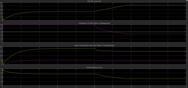
Fig06: Scope01 [Fuel flow rate (lpm), Utilizaton (%), Stack consumption (lpm), Stack efficiency (%)] Vs. Time (t).
For scope-01:
01. Fuel flow rate Vs. time:
Initially the flow of fuel was kept 50 lpm further from 10th second to 13.5th second (spam of 3.5 seconds) the flow was raised upto 85 lpm. Now what happens to the other parameters of the fuel cell we will study one by one.
02. Utilization of fuel Vs. time:
Percentage of utilization of the oxygen remains constant (60 %) before and after the rise in the supply of hydrogen fuel. Whereas the percentage of utilization of hydrogen fuel falls from 99.56% to 45% due to rise in the supply of the hydrogen fuel. Although the supply of fuel is increased but the DC/DC converter will fetch the current according to the requirements of the load therefore we must supply the fuel according to the requirements of the load. In other words it can be said as, more than excess amount of fuel is supplied for very few requirements of the load which results in the lower percentage of utilization of hydrogen fuel.
03. Stack consumption Vs. time:
The consumption of air by the stack gets reduced upto 150 lpm from 180 lpm just after the rise in the fuel flow whereas the consumption of hydrogen by the stack gets reduced upto 40 lpm from 50 lpm. This is due o inherient nature of the fuel cell.
04. Stack efficiency Vs. time:
The efficiency of fuel cell stack also get reduced nearly from 55% to 36% due to rise in the flow of fuel.
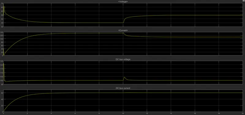
Fig07: Scope02 [Voltage, Current, DC bus voltage, DC bus current] Vs. Time (t).
For scope-02:
01. Satck voltage Vs. time:
Voltage of the fuel cell stack initially gets adjusted to 45 (V) because of the RL load which will have the exponential rise in the current. Therefore we will observe the exponential fall in the voltage. At 10 seconds we are increasing the flow rate from 50 lpm to 85 lpm thus the voltage of the fuel cell stack increases from 45 V to 50 V.
02. Satck current Vs. time:
Current of the fuel cell stack initially gets adjusted nearly to 140 (A) because of the RL load which will have the exponential behaviour. At 10 seconds we are increasing the flow rate from 50 lpm to 85 lpm thus the current due to inherent properties of the fuel cell stack decreases from 140 A to 110 A.
03. DC bus voltage Vs. time:
The bus voltage of the load will not gonna experience any transient because of the control involved in the DC/DC converter. DC/DC converter will not gonna allow any fluctuation in the voltage any other than a 100 V. But at 10th second we will observe a sudden rise in the voltage initially which again is taken under control and adjusted to 100 V by the DC/DC converter.
04. DC bus current Vs. time:
If we are gonna zoom in at 10th second of current we will observe a very small rise in current for that particular instance that is due to rise in flow rate effect of which on the load is further controlled by the DC/DC converter.
Conclusion:
Attempt to draw more power without increasing flow rate will reduce output voltage and may damage the membrane.The value of current increases but the output voltage of a fuel cell decreases which results in lower rates of power and inefficient operation of the fuel cell.Whenever the supply of the fuel to the fuel cell stack increases beyond the load requirements the efficiency of the fuel cell decreases.Therefore fuel we must supply the fuel according to the requirements of the load. As fuel cell cannot store the charge like a battery does which results in losses if the excess fuel is supplied.With increasing supply of the fuel the output voltage of the fuel cell stack increases whereas the current of the fuel stack decreases this inherient behaviour of the fuel cell must be taken into consideration while designing the system.